


Step-by-Step Guide: Setting Work Offsets on Hermle UWF‑851 CNC Mill with Siemens Sinumerik 810 Control
This article briefly describes the whole process of Work Offset Setting on Hermle UWF 851 CNC Mill with Siemens Sinumerik CNC Control.
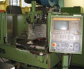
Hermle UWF 851 CNC Mill with SINUMERIK 810 CNC Control
Hold the job in vise with 5 to 10 mm depth.
Milling Cutter Preparation
Tighten (grip) the cutter of Ø 12 mm in Tool Holder using a Tool Holder Tightening Fixture.
Pick the same Tool Holder in your left hand and Press the Tool Change Button to open Tool Change Mechanism located at the right side of the cnc milling machine head.
Place the tool holder in machine head and push upward, with the other hand press Closing Tool Change Button next to the Tool Change Button.
Select Jog Mod and press > (Next Page Button) to find Over Store page. Select Over Store page.
Enter S = 450 (speed rmp) and M = 03 (rotation CW).
Press Cycle Start button. Spindle will start rotating.
Select Incremental Mod, In this Mod, 1 (0.001 mm), 10 (0.01 mm), and 100 (0.1 mm) calibrations can be set for Hand Wheel usage.
Axis such as X, Y, Z, C-axis’s can be selected from key pad area.
Work Offset Setting X-axis
Select 100 (0.1) calibration and press X to active X-axis for movement.
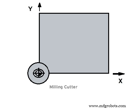
Use Hand Wheel to move cutter closer to the job at the side shown in figure below (X-axis).
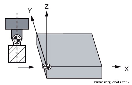
Work Offset Setting in X-axis
Give cutter some depth (5-10 mm).
Now again move in X-axis and when you are closer enough that you can’t see the gap between your job and the cutter, reduce Incremental Mod calibration to 10 (0.01 mm), place a piece of paper between cutter and job.
Keep moving slowly, at one point your paper will cut now stop there, this is the axis position value which is required for offset setting.
Entering X-axis value in Zero Offset
Bring Zero Offset page on cnc control screen by pressing Setting Data tab page and then Zero Offset tab page.
Place X-axis value taken in the above step in Zero Offset (G54 X = ……………….).
Work Offset Setting Y-axis
Select 100 (0.1 mm) Incremental Mod. Select Z-axis to more the cutter upward.
Select Y-axis to move the cutter towards the side shown in figure below.
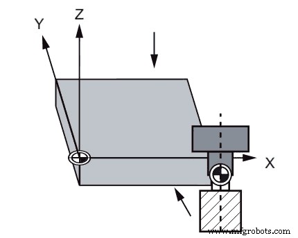
Work Offset Setting Y-axis
Select Z-axis to take 5-10 mm cutter depth.
Select Y-axis to move closer to the job.
When you are enough closer that you can’t see the gap between your job and the cutter, reduce Incremental Mod calibration to 10 (0.01 mm), place a piece of paper between cutter and job.
Keep moving slowly, at one point your paper will cut. Now this is the Y-axis position which will be used for Zero offset setting.
Entering Y-axis value in Zero Offset
Press Setting Data tab page and then Zero Offset tab page to bring Zero Offset page. Now enter Y-axis value taken in the above step by
Place the value in Zero Offset (G54 Y = ………………… ).
Now select 100 (0.1 mm) Incremental Mod. Select Z-axis to more the cutter upward.
Not Finished Yet…
After the above procedure completion, when your program will run at Automatic Mod, your cutter will start (G00 X0 Y0) work at the point shown below which is wrong.
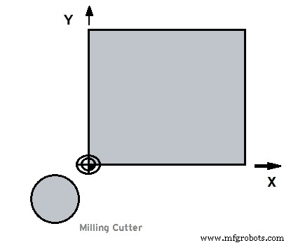
Work Offset Setting tool incorrect position
Last Step
What we want is the cutter to start at Mid point exactly at the top of the job start point, where two sides (whose values are measured above) meet.
As this is the correct point from where all the component dimensions are calculated, See in figure.
Work Offset Setting tool correct position
To correct the cutter position we will subtract the cutter Radius which is 6mm (as our cutter is of Ø12mm ) from X-axis and add 6 mm to Y-axis in Zero Offset X, Y values.
CNC Machine
- Efficient Tool and Work Offset Configuration Using G10 Programmable Data Entry
- Millport SmartLathez 1740 CNC Lathe – Precision & Power
- Fanuc G10 G-Code: Mastering Programmable Offset Settings for CNC Machines
- Precision Tool Offset Techniques for CNC Lathes on Fanuc Controllers
- Haas CNC G10: Precise Programmable Tool & Work Offset Setting via G-Code
- Mastering Tool Offset Setup on SINUMERIK 808D Turning Center
- Sinumerik CYCLE82 Drilling & Counterboring Cycle: Advanced CNC Mill Programming
- Optimizing Haas CNC Mill Settings: A Complete Operator Guide
- Sinumerik 810 CNC Mill Programming: Master Radius & Chamfer Control
- CNC Milling Program: Demonstrating G41 Left Cutter Radius Compensation