


USB‑C Pinout & Features: A Comprehensive Guide for Professionals
USB‑C Overview: Key Features, Pinout, and Power Delivery
Whether you’re designing a new gadget or troubleshooting connectivity, a deep understanding of the USB‑C standard is essential. This guide unpacks the connector’s pin configuration, data‑transfer capabilities, and power‑delivery nuances, all while highlighting how USB‑C’s flexibility drives modern device ecosystems.
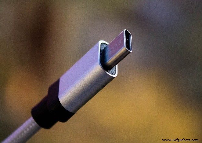
A USB Type‑C port. Image courtesy of Denys Vitali
What Is USB‑C?
USB‑C is the latest USB specification that delivers high‑speed data transfer up to 10 Gb/s and power delivery of up to 100 W (20 V at 5 A). These attributes make it the de‑facto universal connector for smartphones, laptops, and peripherals.
USB‑C vs. USB Type‑C
Both terms refer to the same specification; “USB‑C” is the common shorthand, while “USB Type‑C” is the official name listed on USB.org.
Core USB‑C Features
- Reversible plug: The connector is designed so the plug can be inserted in either orientation.
- Multiple protocol support: It carries USB 2.0, USB 3.0/3.1 Gen 2, and third‑party Alternate Modes like DisplayPort and HDMI.
- Dynamic power negotiation: Devices negotiate voltage and current on the CC line, enabling up to 100 W of power transfer.
Pin Configuration
The USB‑C connector contains 24 pins. Figures 1 and 2 illustrate the pinout for the receptacle and plug, respectively.

Figure 1. USB‑C receptacle pinout. Image courtesy of Microchip.
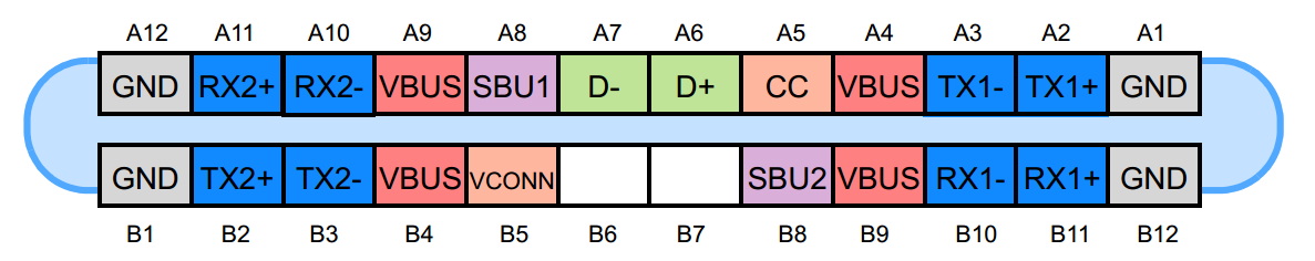
Figure 2. USB‑C plug pinout. Image courtesy of Microchip.
USB 2.0 Differential Pairs
The D+ and D‑ pins provide the USB 2.0 data pair. Although the receptacle contains two D+ and two D‑ pins, only one differential pair is active, with the extra pins ensuring the connector remains reversible.
Power and Ground Pins
VBUS and GND deliver power. While the default VBUS is 5 V, USB‑C allows negotiation of up to 20 V, and the current can be increased to 5 A, yielding a maximum power of 100 W. This capability is particularly useful for charging laptops and power‑hungry peripherals.
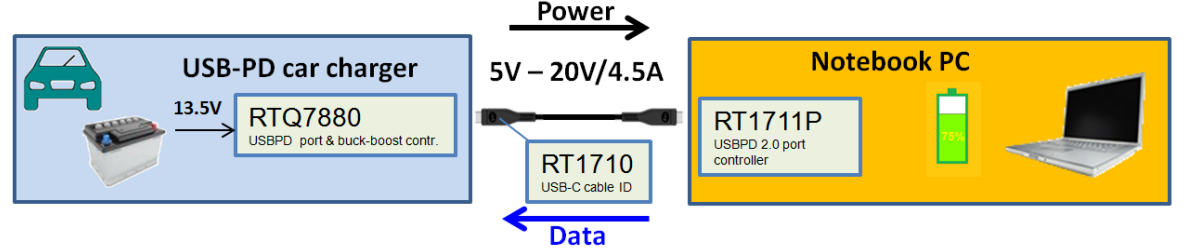
Figure 3. High‑power USB‑C implementation. Image courtesy of Richtek.
USB 3.0/3.1 Data Paths
Two sets of RX and TX differential pairs enable 5 Gb/s (USB 3.0) or 10 Gb/s (USB 3.1 Gen 2) transfers. Because the connector is reversible, a built‑in multiplexer selects the correct pair based on orientation.
CC1 and CC2: Channel Configuration
The CC1 and CC2 pins serve multiple roles: cable attachment detection, orientation sensing, and current capability advertisement. They also carry the single‑wire Power Delivery (PD) protocol.
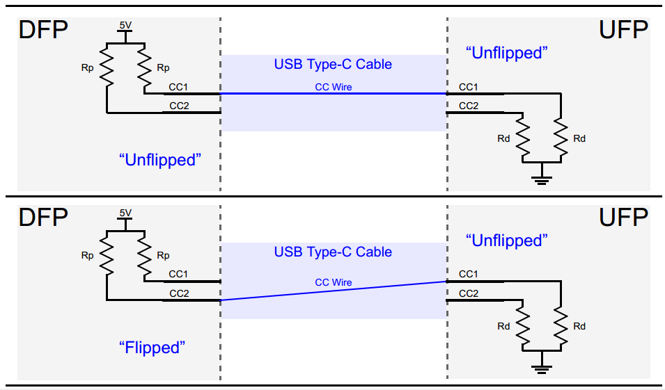
Figure 4. CC1/CC2 orientation detection. Image courtesy of Microchip.
The voltage on a CC line reflects the current rating: ~0.41 V for 500 mA (USB 2.0), ~0.92 V for 1.5 A, and ~1.68 V for 3 A. Devices read this voltage to determine how much power they can safely draw.
VCONN Pin
VCONN supplies 5 V to active cables that host additional circuitry (e.g., re‑drivers, active monitors). The cable’s internal IC pulls down the CC pin (via a unique Ra resistor) to signal the host to power VCONN.
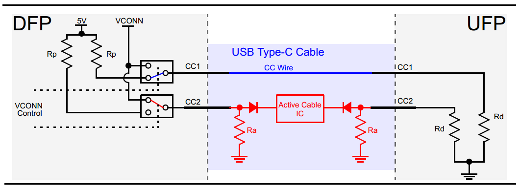
Figure 5. VCONN powering active cable. Image courtesy of Microchip.
SBU1 and SBU2
These pins carry low‑speed signals used exclusively in Alternate Modes, such as DisplayPort or HDMI.
USB Power Delivery (PD)
PD is a protocol that negotiates voltage and current over the CC line. It allows dynamic adjustment of VBUS, enabling scenarios like a 9 V bus for a tablet or 5 V for a phone, all within the same cable.
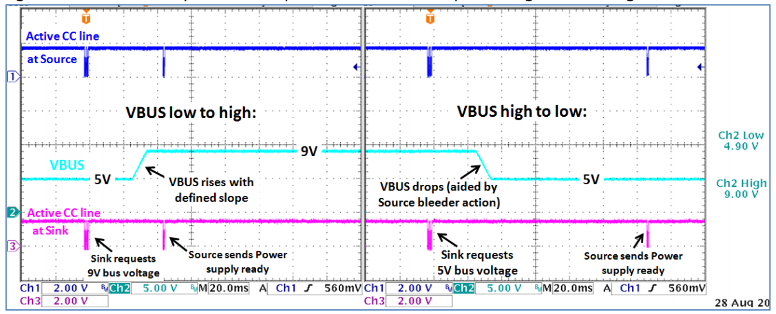
Figure 6. USB PD negotiation flow. Image courtesy of Richtek.
PD also handles Alternate Mode handshakes, making the same connector versatile for data, video, and power.
Alternate Modes
Alternate Modes enable third‑party protocols—most notably DisplayPort and HDMI—to run over USB‑C. They require at least a USB 2.0 link and PD support, ensuring backward compatibility.
Conclusion
USB‑C’s reversible design, high‑speed data transfer, and up to 100 W power delivery make it the cornerstone of contemporary device connectivity. From smartphones to laptops, this standard unifies data, video, and power in a single, adaptable interface.
Explore more of our in‑depth articles here.
Industrial equipment
- Mastering USB‑C: Design Challenges and Practical Solutions for High‑Speed Data and Power
- Everything You Need to Know About USB‑C: Features, Pinouts & Power Delivery
- USB Pinout Explained: A Comprehensive Beginner’s Guide
- Trimpot Pinout Explained: Features, Applications, and Configuration Guide
- LM393 Comparator Overview: Pinout, Features, Applications & Operation
- TIP122 Pinout Guide: Features, Functions, and Practical Usage
- 2N3771 NPN Transistor: Pinout, Key Features, Applications & Alternatives
- CH304G USB Interface Chip: Features, Applications, and Schematic Overview
- A4988 Stepper Motor Driver Pinout: Complete Guide to Features, Wiring, and Operation
- AT89C51 Microcontroller: Overview, Pinouts, Programming Tips & Alternatives