


Mastering USB‑C: Design Challenges and Practical Solutions for High‑Speed Data and Power
USB Evolution: From 1.1 to 3.2 and Beyond
First launched in 1996, the universal serial bus (USB) unified the roles of multiple connection types and is ubiquitous in computing and consumer tech. Its introduction made connecting peripherals—keyboards, mice, printers, cameras, external drives, and more—simple and convenient. Devices no longer needed distinct interfaces, and users could plug anything into a single standard cable.
USB 1.1 supported a maximum data rate of 12 Mbps. With USB 2.0, the speed jumped to 480 Mbps, enabling video streaming and rapid data transfer to PCs. The 5 V, 2.5 W VBUS also allowed small devices and smartphones to charge without extra adapters, a requirement adopted by the smartphone industry in 2007 to reduce e‑waste.
Today’s smart devices demand even higher interconnect bandwidth. Streaming HD and 4K video, and exchanging data with multi‑gigabit storage, require interfaces like HDMI (6 Gbps), DisplayPort (8.1 Gbps), and Thunderbolt (20 Gbps). To keep USB at the forefront, the USB Implementer’s Forum introduced USB 3.2 with three transfer rates: 5 Gbps (Gen 1), 10 Gbps (Gen 2), and 20 Gbps (Gen 2x2). USB 4 follows, offering 20 Gbps and 40 Gbps speeds while remaining compatible with USB 3.2, USB 2.0, and Thunderbolt 3. USB 4 adds a connection‑oriented tunneling architecture that multiplexes multiple protocols over a single physical interface.
Upgrading the Physical Connection
Supporting dual‑lane high‑speed standards while maintaining backward compatibility with legacy USB 2.0 requires a new physical interface: USB‑C. The USB‑C connector adds two sets of differential data channels, a USB 2.0 bus, and support for the USB Power Delivery (USB‑PD) specification. It also provides two power/ground pairs and a communication channel for negotiating power levels ranging from 5 V (USB 2.0) to 20 V / 5 A (100 W). Side‑band uses (SBU) enable future enhancements.
click for larger image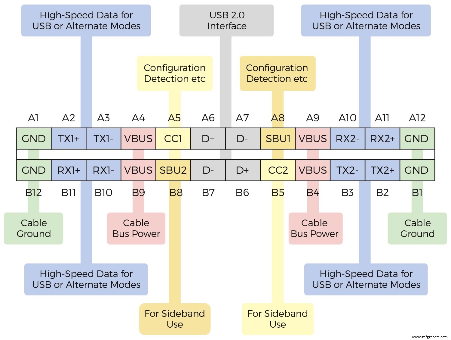
Figure 1. USB‑C Connector Pins (Source: Diodes Inc.)
The non‑polarized design lets users insert the cable in either orientation, and the 24 pins accommodate the extensive power and data needs of USB 3.2, USB 4, and USB‑PD, while also supporting USB 2.0 for legacy devices. Bidirectionality allows each end of the cable to act as host, device, power supplier, or consumer.
Implementing USB‑C
USB‑C’s flexibility and expanded pin count make it considerably more complex than earlier connectors. Devices must be classified as downstream facing port (DFP / source), upstream facing port (UFP / sink), or dual‑role port (DRP) that can source and sink data and power. Logic must handle configuration control, detect cable orientation, route USB 3.2 and DisplayPort signals, multiplex USB 2.0 traffic, switch power paths, and provide charge control, signal integrity, and transient‑voltage protection.
A notebook or tablet typically integrates a fully functional USB‑C interface that manages USB 3.2, multimedia data, and USB‑PD. Figure 2 illustrates the circuitry required for such a design.
click for larger image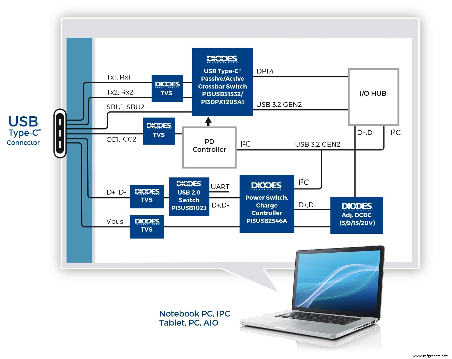
Figure 2. USB‑C Interface Supporting USB 3.2 Multimedia, and USB‑PD (Source: Diodes Inc.)
Bidirectional matrix switches, such as the Diodes PI3USB31532, provide an integrated solution that multiplexes USB 3.2 Gen 2 (10 Gbps) and up to four DisplayPort 1.4 lanes, along with auxiliary channels. Designed for low insertion loss and a –3 dB bandwidth of 8.3 GHz, the switch preserves signal fidelity at 10 Gbps. For longer traces, an active mux like the 6‑channel, 4‑lane PI3DPX1205A1 adds a ReDriver, linear equalization, and flat‑gain output, doubling signal integrity over comparable CMOS ReDrivers.
USB‑PD is handled by a dedicated controller that enables up to 100 W over the USB‑C connector and allows alternative modes such as DisplayPort or Thunderbolt. A device like the PI5USB2546A manages charging port control, a 2.4 A power switch, and USB 2.0 D+/D‑ switching. It supports the USB Battery Charging 1.2 spec, including CDP and DCP modes, making it suitable for wall chargers, hosts, and hubs.
click for larger image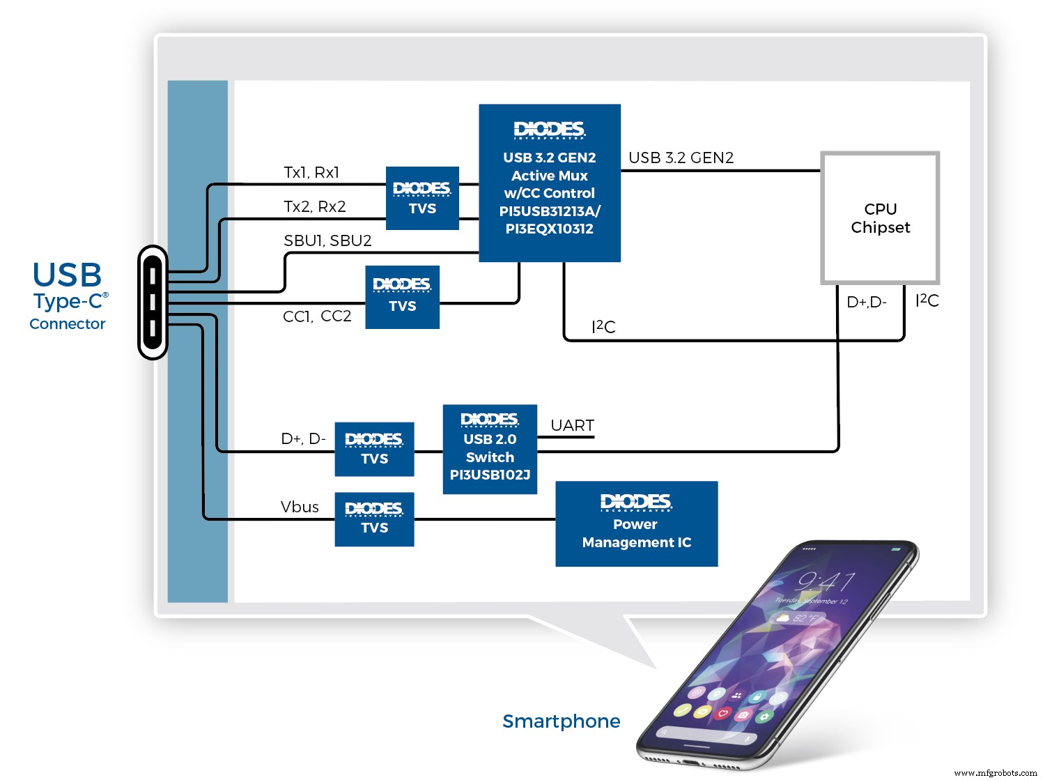
Figure 3. Implementing USB‑C in Smartphones (Source: Diodes Inc.)
Figure 3 shows a smartphone‑grade USB‑C implementation using the Diodes PI5USB31213A, which integrates the USB‑C configuration channel controller and USB 3.2 Gen 2 (10 Gbps) multiplexing. It automatically configures host, device, or DRP modes based on CC pin voltage, detects cable orientation, and negotiates charging currents. Alternatively, the PI3EQX10312 offers the same functions plus a ReDriver for longer traces.
click for larger image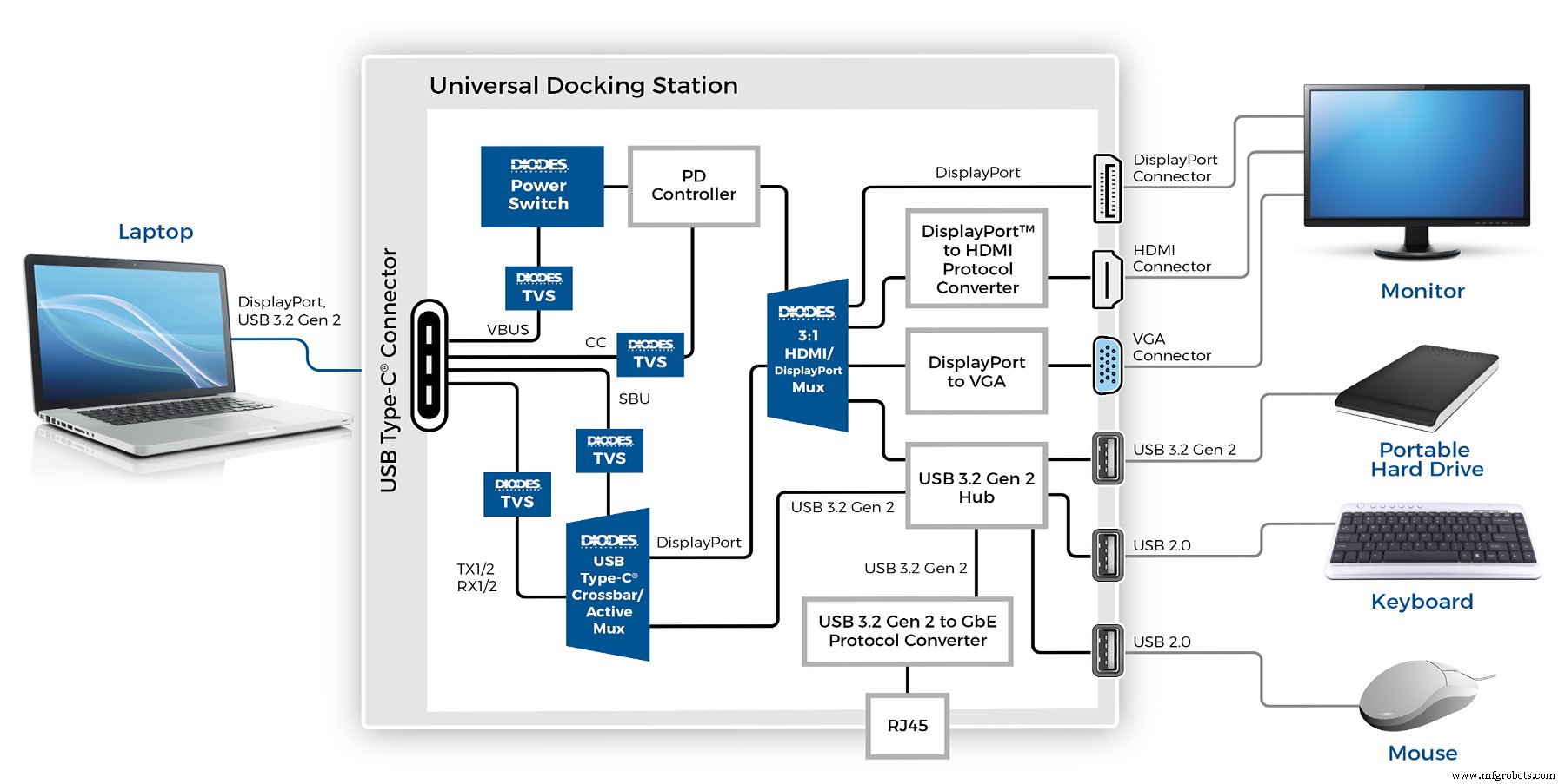
Figure 4. USB‑C Dock (Source: Diodes Inc.)
Figure 4 depicts a universal docking station that connects to a host via a single USB‑C port and provides DisplayPort, HDMI, VGA, multiple USB 3.2 outputs, and a Gigabit Ethernet port. Devices such as the PI3USB31532 or PI3DPX1205A1 handle USB 3.2 and DisplayPort switching, while a power switch supplies up to 100 W to the host. Output from the DisplayPort switch (e.g., PI3WVR31310A) feeds directly to a DP connector or through HDMI/VGA converters.
Conclusion
Designers face significant complexity when implementing USB‑C, but the benefits—up to 100 W power delivery, 10 Gbps or 20 Gbps data rates, and multi‑protocol support—are compelling. Integrated solutions for data switching, power management, charge control, and cable‑orientation detection simplify the design process, reduce board space, lower BOM costs, and streamline certification.
Embedded
- Mastering OTA Updates: 5 Common Challenges & Proven Solutions for Industrial IoT
- Synchronizing Asynchronous Resets in ASICs and FPGAs: Challenges, Best Practices, and Advanced Solutions
- USB‑C Pinout & Features: A Comprehensive Guide for Professionals
- Reactive Maintenance: Common Challenges, Proven Solutions, and the Path to Proactive Asset Management
- Enhancing Industrial Performance: Overcoming Monitoring Challenges with IoT & Analytics
- Metal 3D Printing: Overcoming Key Challenges & Harnessing Emerging Solutions
- Industrial IoT Security: Overcoming Challenges and Implementing Robust Solutions
- Revolutionizing Automotive Production: Overcoming Manufacturing Challenges with IoT Solutions
- Overcoming Challenges in RF PCB Design: Proven Solutions for Reliable Performance
- Optimizing High-Speed PCB Design: Tackling Signal Integrity Challenges