


Programming ATmega328P & ATtiny45 with Atmel Studio 7 – Breadboarding & Software Setup
In this guide we’ll build breadboard circuits for programming the ATmega328P and ATtiny45 microcontrollers and walk through the necessary software configuration.
We’ll detail the construction of two similar circuits—one for the ATmega328P and one for the ATtiny45—providing full schematics, clear photographs of the solderless breadboard assemblies, and an introduction to the Atmel Studio 7 IDE.
Hardware Overview
The ATmega328P is a 28‑pin AVR microcontroller best known as the core of the Arduino platform. It offers 32 kB flash, 2 kB SRAM, and 23 I/O pins, making it suitable for a wide range of projects. The ATtiny45 is an 8‑pin companion with 4 kB flash, 512 B SRAM, and 5 I/O pins—great for compact applications.
Both devices are programmed over SPI (MOSI, MISO, SCK, GND). SPI is a synchronous serial bus that allows the master (the programmer) to control the clock and data flow to the microcontroller.
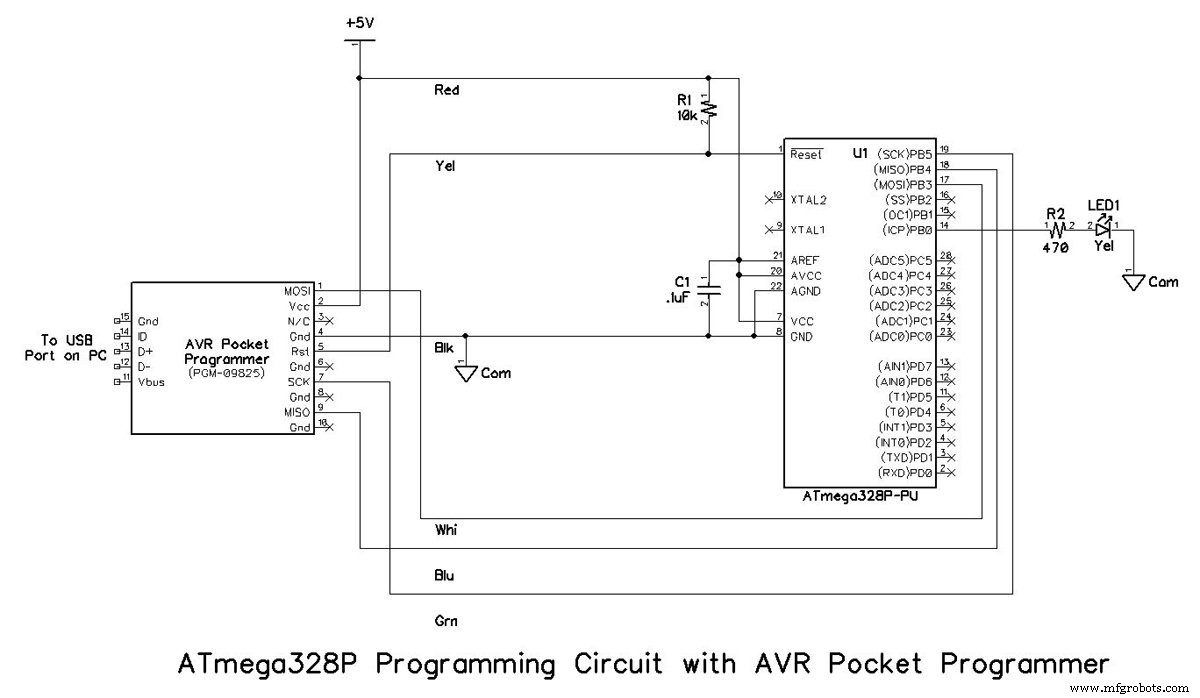
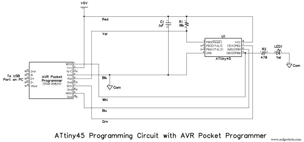
Programming Circuits
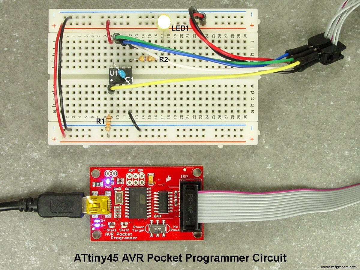
Below are the schematic diagrams. R2 and LED1 are optional; they serve as a simple test circuit once the microcontroller is programmed.
Programmer Options
The Atmel‑ICE is a premium choice, but the budget‑friendly Sparkfun AVR Pocket Programmer is sufficient for most hobbyists. Ensure your chosen programmer supports SPI and that you have installed the correct driver before first use. The AVR Pocket Programmer’s 2×5, 2×5 (9 in) and 2×3 ribbon connectors are shown in the photos below.
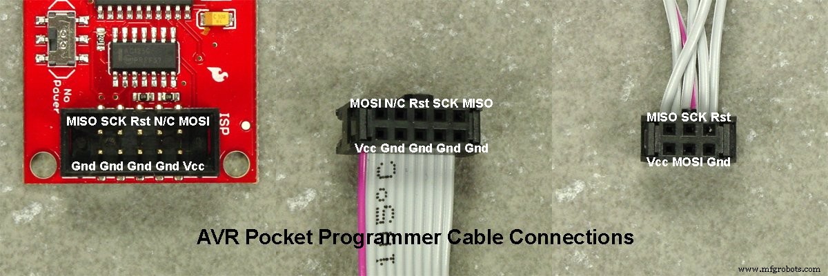
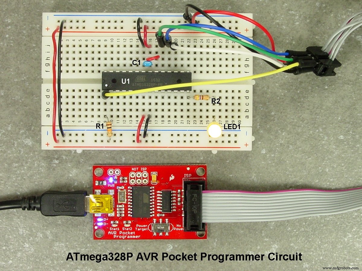
Breadboard Assembly
Six short jumper wires connect the 2×3 female connector to the microcontroller pins on the breadboard. Wire colours match the schematic.
Parts List
| Part Ref. | Description | Source | Item No. |
|---|---|---|---|
| U1 | IC, ATmega328P‑PU, 32 kB Flash, DIP‑28, 1.8‑5.5 V | Digi‑Key | ATMEGA328P‑PU‑ND |
| U2 | IC, ATtiny45‑PU, 4 kB Flash, DIP‑8, 2.7‑5.5 V | Digi‑Key | ATTINY45‑20PU‑ND |
| R1 | Resistor, ¼ W, 10 kΩ | Digi‑Key | 10KQBK‑ND |
| R2 | Resistor, ¼ W, 470 Ω | Digi‑Key | 470QBK‑ND |
| LED1 | LED, Yellow, 3/4" T1 | Digi‑Key | 754‑1889‑ND |
| C1 | Capacitor, Ceramic, 0.1 µF, 50 V | Digi‑Key | 399‑9797‑ND |
| PGM | AVR Pocket Programmer | Digi‑Key | 1568‑1080‑ND |
| BB | Solderless Breadboard, 400‑Contact | Digi‑Key | 377‑2094‑ND |
Software Setup
AVR Pocket Programmer Driver
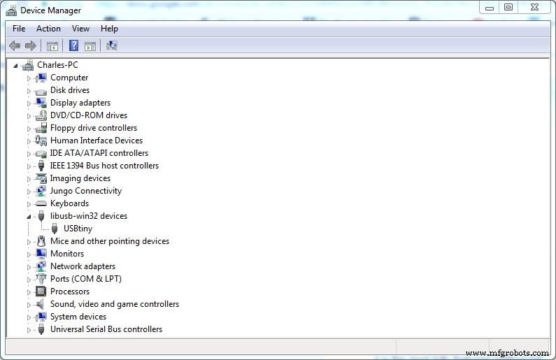
Download the Windows driver from the Adafruit USBtinyISP page. Choose the ZIP containing two installers—32‑bit and 64‑bit. Install the appropriate one, then connect the programmer with a USB‑A to Mini‑B cable. The blue PWR LED and red Stat1 LED should light; the two blue data LEDs may flicker. After installation, the device appears in Device Manager under "USBtiny" (libusb‑winXX).
Atmel Studio 7
Atmel Studio 7 is the flagship IDE for AVR development on Windows (both 32‑bit and 64‑bit). While not the only option, it provides the most comprehensive toolset for building, debugging, and flashing AVR firmware. Download and install the IDE, and refer to the user guide for advanced features.
Programmer support is built‑in for many devices, but the AVR Pocket Programmer isn’t listed by default. It can be used via AVRDude, a command‑line utility that communicates with AVR microcontrollers.
AVRDude
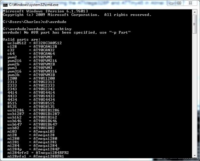
AVRDude is available for Windows and Linux. At the time of writing, version 6.3 is the latest release. Download avrdude-6.3-mingw32-zip, unzip it (ideally to a root directory for simplicity), and run the following to verify installation:
- Open Command Prompt.
- Navigate to the AVRDude folder.
- Execute
avrdude -c USBtiny– you should see a list of supported AVR devices.
Putting It All Together
With the hardware assembled and drivers installed, you’re ready to flash firmware. Download New_Blink.zip, unzip it, and follow the steps below.
- Launch Atmel Studio 7.
- File > New Project. Select "GCC C Executable Project", name it New Blink, and click OK.
- Choose the target device: ATmega328P or ATtiny45, then click OK.
- Tools > External Tools > Add. Title the tool (e.g., "AVRDude – ATmega328P").
- Command:
C:\Path\To\AVRDude\avrdude.exe(replace path). - Arguments: for ATmega328P, use
-c usbtiny -p m328p -v -U flash:w:$(TargetDir)$(TargetName).hex:i; for ATtiny45, use-c usbtiny -p t45 -v -U flash:w:$(TargetDir)$(TargetName).hex:i. - Initial directory:
C:\Path\To\AVRDude. Check "Use Output window". - Apply & OK.
- Open the provided
New Blink.cfile, copy its contents, and paste into the Atmel Studio editor. - Rename the source file to New Blink.c via Solution Explorer.
- File > Save All.
- Build > Build Solution.
- Tools > AVRDude – ATmega328P (or ATtiny45). The compiled firmware is uploaded, and LED1 will flash at 1 Hz.
Although the process may seem involved for a simple LED blink, you’ve now mastered four essential skills: building a programming board, installing an IDE, integrating AVRDude, and configuring a custom tool. Future projects will be even smoother.
Try the project for yourself and grab the BOM for quick assembly.
Industrial equipment
- Why Bolts and Nuts Are Hexagonal: The Engineering Behind the Shape
- Die Casting: Advantages, Challenges, and Key Insights for Manufacturers
- Mastering Multicore Programming & Debugging: Strategies for Performance & Reliability
- Mastering G and M Codes: A Comprehensive Guide to CNC Programming
- Understanding DC vs AC Motors: Key Differences and Buying Guide
- Should You Coat Your Pump? Weighing the Benefits and Drawbacks
- Selecting the Optimal CNC Cutter and Programming for Peak Performance
- Expert Plant Automation: Design, Implementation, and Turnkey Solutions
- Understanding Pressure vs. Flow in Compressed Air Systems
- Preventing Pump Failures: The Impact of Contamination on Hydraulic Systems