


Modern Documentation Practices for Integrated PCB and Mechanical Design
When I worked at Control Data’s subsidiary, every schematic, mechanical drawing and PCB was assigned a unique, sequential identifier. Although I was in the documentation department, I still don’t recall the exact process that brought the minicomputer together.
Back then all drawings were hand‑sketched. Draftsmen would transfer the schematic onto vellum (or tracing paper) using standard symbols and stencils. PCB layout was done with dot‑and‑tape, while mechanical engineers produced packaging drawings on a drafting table. Communication flowed through memos, reports and face‑to‑face meetings. I later wrote a blog titled How It Was: PCB Layout from Rubylith to Dot and Tape to CAD to document those memories.
With the rise of CAD, drawings became digital, but the workflow stayed essentially the same: the schematic fed the netlist, the PCB output was converted to a .dxf for AutoCAD, and the resulting files could be grouped and categorized. The new electronic format simply made the paper trail easier to manage.
Modern products are built in stages, creating sub‑assemblies that introduce additional complexity. When you have multiple builds that use different components, the documentation hierarchy must reflect the level at which the schematic and other drawings belong. Is the schematic tied to the earliest generic design, or does each build have its own version with updated component values? The answer depends on its intended use—debugging, production, or service.
Over the years our documentation system evolved in an ad‑hoc manner, influenced by personnel from various backgrounds. I adopted a principle from aerospace: each document should exist in only one place. Duplicate documents create confusion and increase error risk.
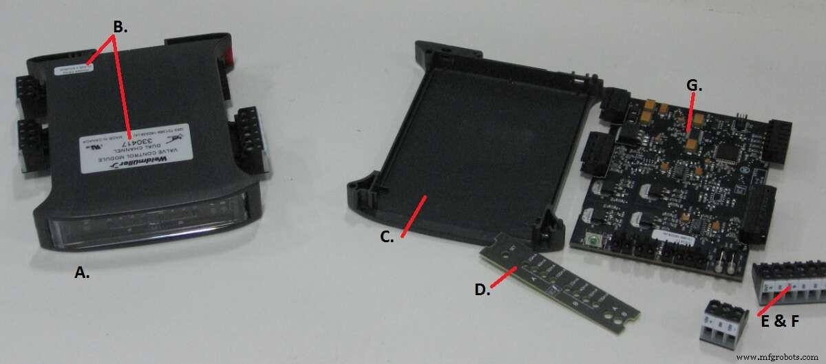
Figure 1. A complex product. The full bill of materials for component A includes drawings for side labels (B), housing (C), front panel (D), plug‑in connectors (E & F), a sub‑assembly (G) and firmware for the microcontroller on G. Where in the hierarchy should the schematic reside? (Source: Author)
Each product receives a catalog number—usually assigned sequentially. Documents at the top level use a letter prefix, the catalog number, and a revision suffix. For example, the schematic (rev C) for catalog number 330924 is W330924C; the mechanical drawing (ref F) is M330924F; the BOM (rev G) is P330924G. Sub‑assemblies receive their own sequential numbers (e.g., SB00123), and their documents follow the same prefix–number–suffix pattern. Documents appear only where needed; the schematic, for instance, resides at the level of the common antecedent. Component values that vary across builds are flagged with a symbol indicating that the value is defined on the BOM. Mechanical assemblies and firmware follow the same scheme. The PCB itself receives a sequential number and revision—no prefix.
Today’s CAD ecosystems, such as Altium, integrate schematic, PCB, assembly drawings, mechanical drawings and even firmware into a single design environment. Draftsmen often insist that the PCB is the physical manifestation of the schematic, so both must stay in lockstep. When a component value changes, the PCB revision must change too. The question becomes: what number should the schematic, assembly and mechanical drawings carry whenever the PCB changes (even for trivial updates like silk‑screen edits)? Are they tied to the catalog number or the PCB number? And how do you ensure that engineers see the updated drawing rather than the one automatically bundled with the PCB package?
Best‑practice solutions exist. Adopt a Product Data Management (PDM) system that enforces a single source of truth, version control, and clear document hierarchies. Use a consistent numbering scheme such as:
- Catalog Number (CAT): Unique product identifier (e.g., 330924).
- Component ID (CMP): Sequential sub‑assembly number (e.g., SB00123).
- Document Prefix:
Wfor schematics,Mfor mechanical,Pfor BOM,Rfor PCB layout. - Revision Letter: A, B, C… for each change.
When a change occurs, update the relevant document’s revision and create a new version of the entire design package. Store the design files in a centralized repository with access controls and audit trails. Link each revision to the BOM so that manufacturing, QA and service teams always reference the correct version.
For additional guidance, consult standards such as ISO 9001 (quality management), IEC 61360 (product data), and IEEE 1557 (electronic design management). If you’re looking for academic research, many PhD candidates publish on documentation frameworks in engineering journals. Reach out to professional groups like the Association for Manufacturing Technology (AMT) or the Institute of Electrical and Electronics Engineers (IEEE) for case studies and templates.
Implementing a modern, consistent documentation system will reduce errors, accelerate time‑to‑market, and build confidence across engineering, manufacturing, and support teams.
Embedded
- Titanium: From Its 18th‑Century Discovery to Today’s High‑Performance Applications
- Evaporated vs. Condensed Milk: Production, History, and Quality Standards
- Butter vs. Margarine: History, Production, and Health Insights
- Embedded World 2017: Key Trends Shaping the Embedded Systems Landscape
- Maintenance & Reliability: Why ‘Good Enough Never Is’ Drives Business Success
- Building Allies: The Key to Success in Maintenance & Reliability
- Loctite and Duct Tape: Why Quick Fixes Fail on Industrial Equipment
- Choosing the Right PLC and Documentation System for Your Manufacturing Application
- The Critical Role of Accurate Documentation in Engineering Success
- Electronic Circuit Breaker: Design, Schematic, and Operation Explained