


Ensuring Power‑Up Phase Determinism with PLL Synthesizers and System‑Level Calibration
In the first part of this series we examined how to guarantee a known, deterministic phase for every channel in complex RF subsystems that integrate multiple DSP blocks, wide‑band DACs, and ADCs. This second installment focuses on PLL‑synthesizer phase adjustments, scalability to larger arrays, and a compact system‑level calibration algorithm that works without external equipment.
PLL Synthesizer Phase Adjustments
We selected PLL ICs that provide fine‑grained, per‑digitizer phase tuning. Temperature‑induced drift in the PLL’s phase relationship with the SYSREF is counteracted by a feedback loop that forces the first transmit channel of each digitizer to lock to the first channel of the reference IC. The first transmit channel emits a unique signal (Figure 1) that, together with the other three channels, is routed to a common receiver (Rx0). Simultaneous reception of all channels enables cross‑correlation to extract the complex phase offsets, ΦTxOffset.
Each PLL contains a voltage‑controlled oscillator (VCO) operating at fVCO_PLL. The measured offsets relate to the required PLL adjustment, ΦPLL_Adj, and the carrier frequency fcarrier by the expression shown in Equation 1.
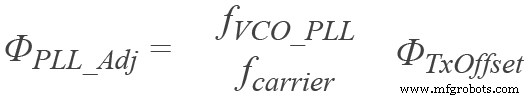
Figure 1. PLL‑synthesizer phase adjustment aligns the first transmit channel of each digitizer IC.
Applying ΦPLL_Adj establishes a common transmit baseline across all digitizer ICs for every power cycle (Figure 2). The open circles denote the first cycle; solid dots represent subsequent cycles, demonstrating that the calibrated transmit phase offsets for the first and second channelizers remain aligned despite varying thermal gradients.
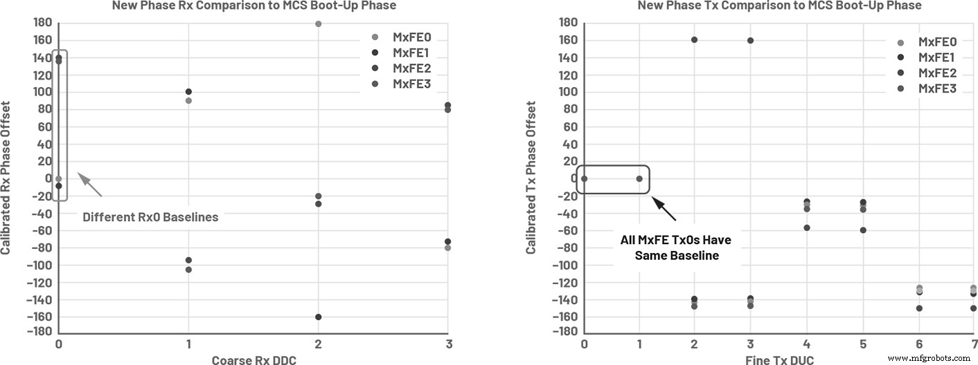
Figure 2. Adjusting the PLL phase aligns the first transmit channel of all digitizer ICs.
Figure 3 shows that temperature variations across the platform—induced by different fan airflows—are effectively compensated. The tight clustering of identical‑colored dots in the top plots confirms deterministic receive and transmit phase offsets after PLL adjustment, regardless of the thermal gradient. The polled register values in the bottom right confirm that the SYSREF–LEMC phase relationship is neutralized.
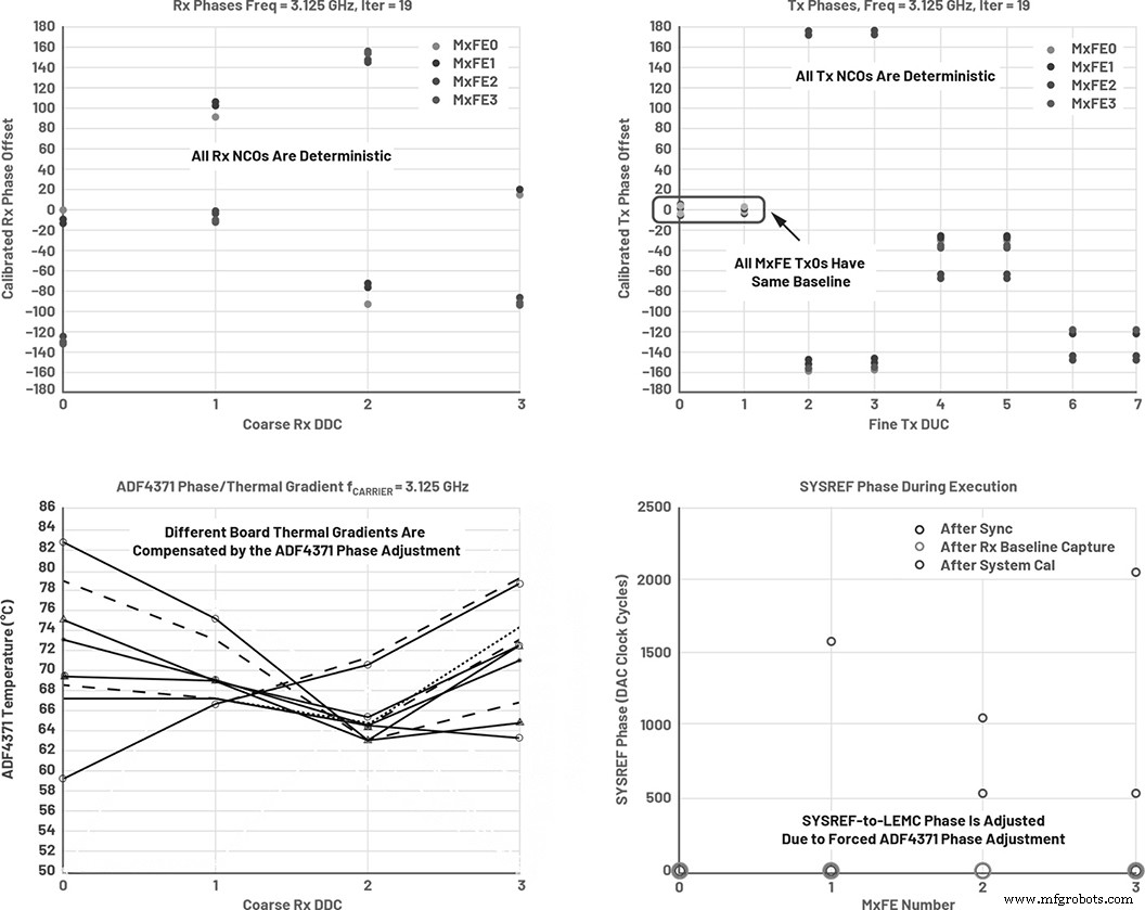
Figure 3. MCS combined with PLL phase adjustment yields power‑up phase determinism across all channels, even under thermal stress.
Multiple RF frequencies were tested to confirm the robustness of the MCS and PLL approach. Figure 4 lists the frequencies used, chosen to cover both integer and non‑integer multiples of the reference clock and LEMC.
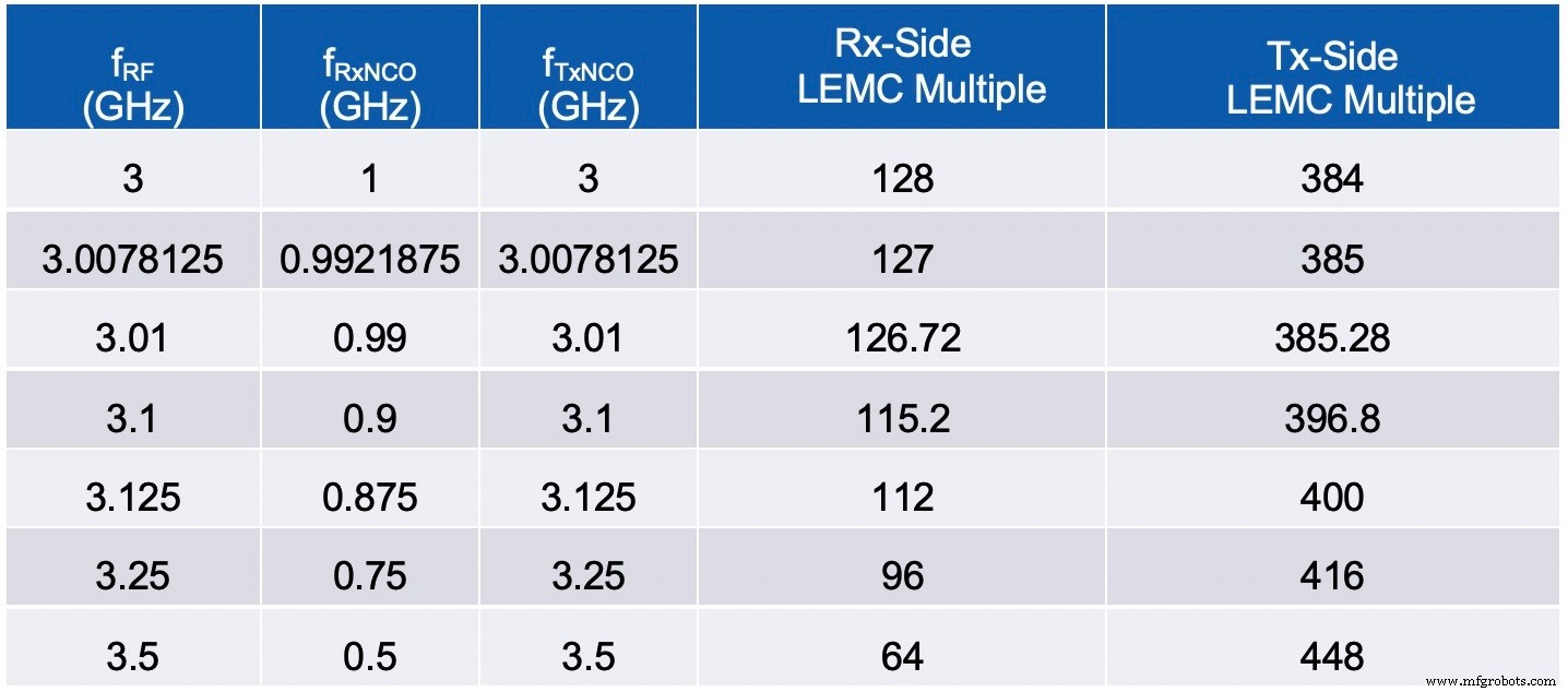
Figure 4. RF frequencies demonstrating MCS performance across diverse clock sources.
Scalability to Multiple Subarrays
While the data presented focuses on subarray‑level performance, the same principles extend to full arrays. An array‑level clock tree distributes SYSREF requests and baseband processing (BBP) clocks to each subarray in a single sample‑clock cycle. Each subarray then generates the required SYSREFs and BBP clocks for its digitizers, ensuring global synchronization across the entire system.
System‑Level Calibration Algorithm
Although MCS provides deterministic phase per channel, trace length variations in the RF front‑end can still introduce inter‑channel offsets. To resolve this, we implemented a self‑contained calibration routine that uses a baseband waveform injected into each channelizer.
The waveform consists of a single‑period pulse per transmit channelizer (Figure 5). Pulses are staggered so that only one pulse is emitted at a time, and the combined signal is routed back to all receive channels. A simultaneous capture yields a 4096 × 16 matrix of samples, one for each of the 16 receive channels.
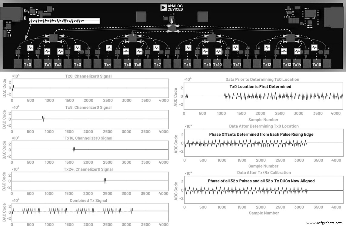
Figure 5. System‑level calibration aligns all receive and transmit channels using MCS and a baseband pulse sequence.
Vertical analysis identifies the pulse from Tx0 in the Rx0 column; subsequent pulses are located accordingly. The complex phase of each pulse’s rising edge is calculated and stored in a 1 × 16 vector. With Tx0 as the reference, all transmit NCO phases are adjusted to match.
Horizontal analysis across the matrix determines the receive channel phases relative to Rx0. The resulting 1 × 16 vector is used to update the receive NCOs, achieving phase alignment across the subarray (Figure 6). While amplitude alignment is not inherent, the on‑chip FIR filters can correct any amplitude mismatches without excessive FPGA resources.
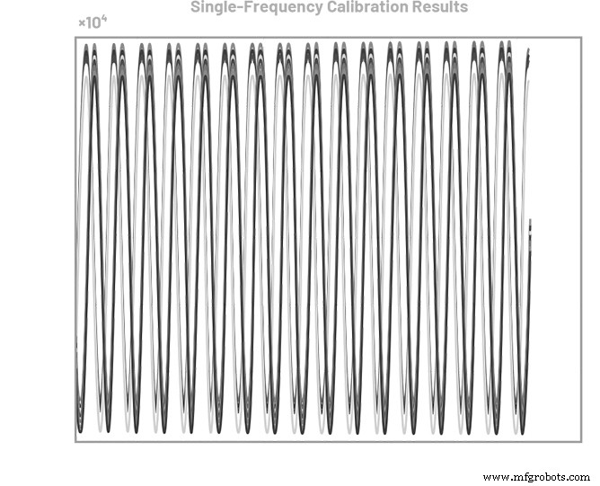
Figure 6. 16‑channel receive I/Q phase alignment achieved via MCS and system‑level calibration.
Implemented in MATLAB® this routine completes in roughly three seconds. An HDL implementation would reduce the time further while remaining self‑contained. If system frequency and amplitude are known at boot‑up, phase offsets can be loaded from a lookup table created during factory calibration, eliminating the need for repeated measurements.
Conclusion
The article demonstrates a complete MCS workflow using four Analog Devices AD9081 MxFET® ICs, thermal compensation with ADF4371 PLLs, and an HMC7043 clock IC for JESD204C distribution. MCS simplifies boot‑time calibration and delivers deterministic phase across multiple frequencies and thermal conditions. The accompanying calibration algorithm populates lookup tables, dramatically reducing system start‑up time. This solution—known as the Quad‑MxFE platform—is ideal for phased‑array radars, electronic warfare, instrumentation, and 5G base‑stations.
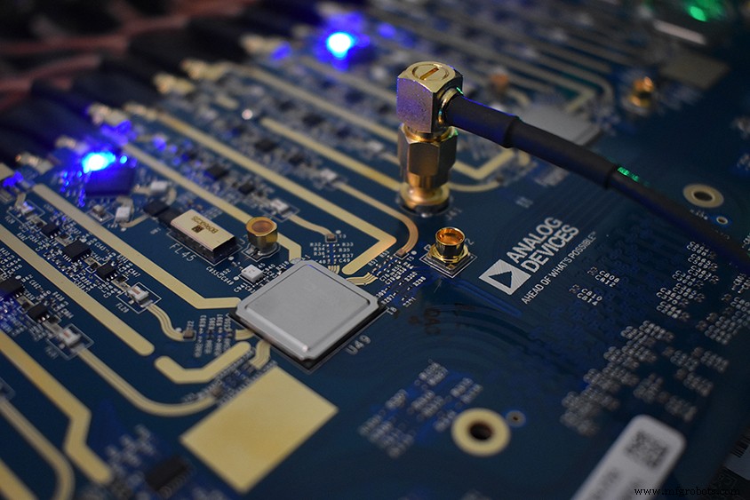
Figure 7. The Quad‑MxFE platform is available for purchase from Analog Devices.
References
- Del Jones. “JESD204C Primer: What’s New and In It for You—Part 1.” Analog Dialogue, Vol. 53, No. 2, June 2019.
- Del Jones. “JESD204C Primer: What’s New and In It for You—Part 2.” Analog Dialogue, Vol. 53, No. 3, July 2019.
Embedded
- Three Key Reasons DevOps and Cloud Are Interdependent
- Representing AC Voltages and Currents as Vectors
- Measuring Frequency and Phase in AC Power Systems
- Sensor Calibration Explained: Definition, Methods, and Key Applications
- Power‑up Phase Determinism: Leveraging Multichip Synchronization in High‑Speed ADC/DAC Platforms
- Renesas RSSK: Rapid Analog Sensor Evaluation & Calibration with RX23E‑A 24‑Bit MCU
- Molding vs Casting: Key Differences and Benefits for Carbon Fiber Parts
- Streamline Electrical Harness Design with E3.cable, E3.topology, and E3.formboard
- Choosing the Right Milling Machine: Types & Applications Explained
- Master Bed Leveling: How to Calibrate Your 3D Printer Base for Perfect Prints