


Designing Multi‑Antenna PCB Layouts: Best Practices for Co‑existence and Isolation
Why Multi‑Antenna Design Matters
Modern mobile devices routinely host several wireless interfaces—4G/LTE, Wi‑Fi, Bluetooth, and GNSS—within a single PCB. Designing for more than one antenna is not trivial; the antennas must coexist without degrading each other’s performance. This guide covers the key factors that influence antenna behaviour, from radiation patterns to isolation techniques, and shows how to layout a PCB that delivers reliable, high‑quality signals.
Co‑existence Fundamentals
When multiple antennas are packed into a device, the term in‑device coexistence refers to their ability to operate simultaneously without significant mutual interference. The design goal is to achieve adequate isolation while maintaining each antenna’s radiation efficiency.
Key Design Rules
- Keep antennas away from noisy components such as voltage regulators and digital logic.
- Provide a clean, continuous ground plane beneath each antenna to support proper radiation.
- Maintain a clear space below the antenna throughout the PCB stack‑up.
- When antennas share the same ground plane, use techniques like etched vias to break ground‑plane continuity and reduce coupling.
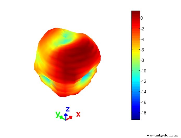
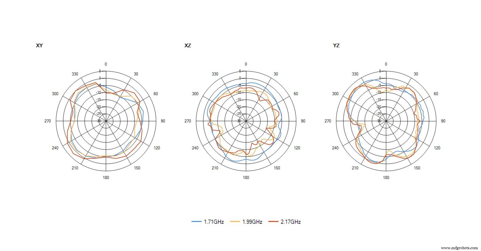
Radiation Patterns and Polarisation
Every antenna has a characteristic radiation pattern—often displayed as a 3‑D shape and a 2‑D cross‑section in the datasheet. The pattern shows how the antenna radiates around its axis, with the strongest emission perpendicular to the antenna’s long axis (its polarisation).
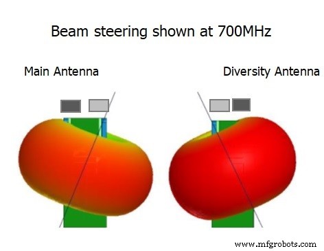
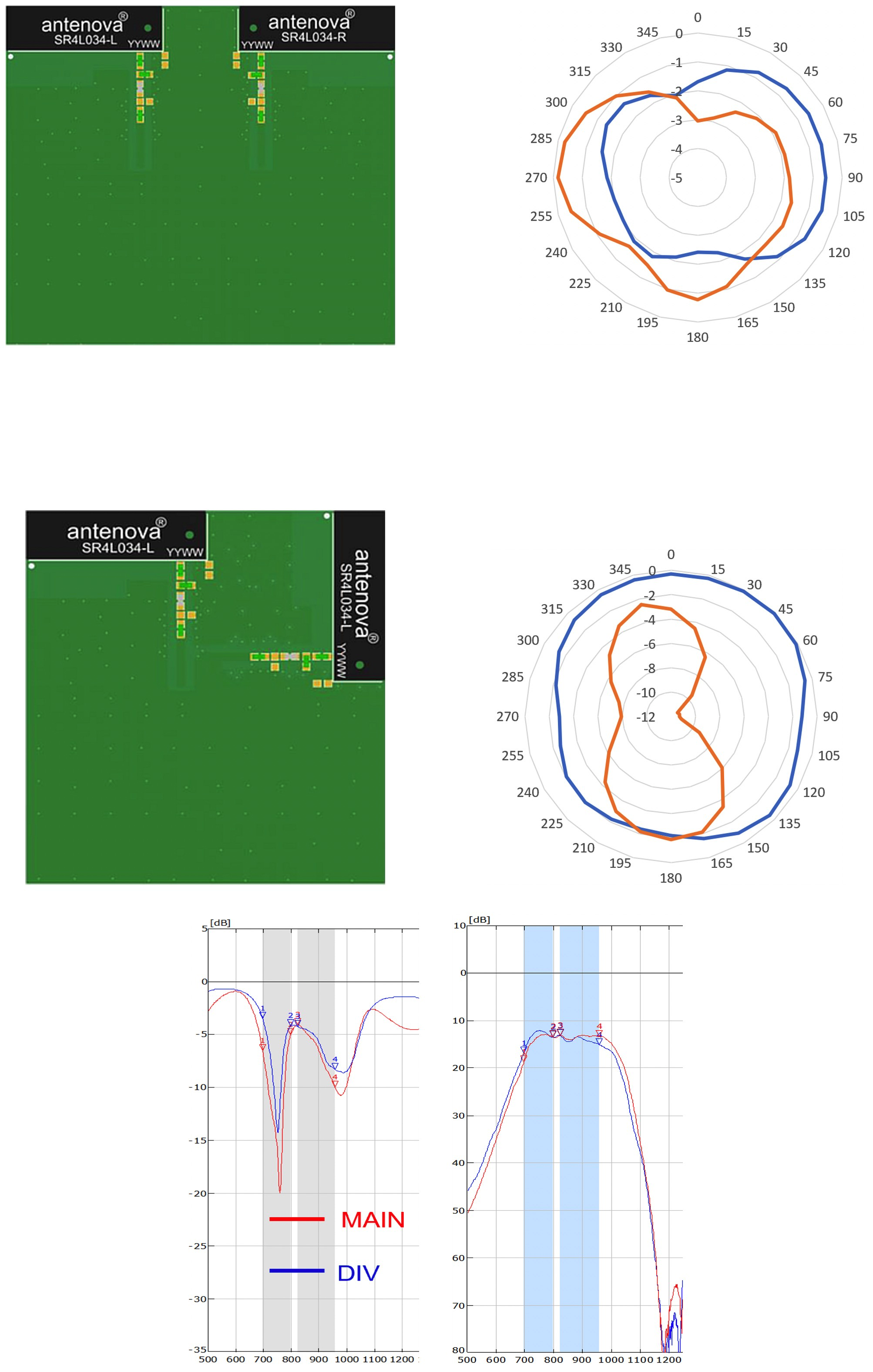
Diversity Antennas
Diversity exploits two antennas on the same frequency to improve link reliability. The first antenna is the primary; the second is the diversity element. By positioning the two antennas in distinct spatial zones—typically 90° apart and separated by at least a quarter wavelength—you reduce mutual coupling and create complementary radiation patterns.
In a diversity configuration, both antennas transmit simultaneously, and the receiver selects the stronger signal. This strategy is especially effective in mobile environments where multipath fading is common.
Reducing Antenna‑to‑Antenna Coupling
Coupling can distort an antenna’s input impedance and reduce radiation efficiency. Common mitigation techniques include:
- Increasing physical separation (e.g., 20–40 mm for many LTE antennas).
- Using isolation structures such as etched ground‑plane vias.
- Applying beam‑steering filters to attenuate one antenna’s signal at the frequency band of the other.
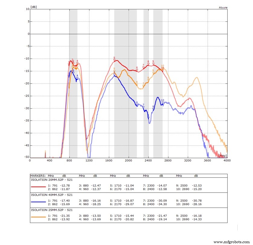
Isolation Between Different Frequency Antennas
Antennas operating on distinct bands must be electrically isolated to prevent cross‑talk. Isolation is quantified by the S21 coefficient measured with a network analyser. Practical strategies include:
- Physical separation guided by each antenna’s radiation pattern.
- Selective filtering that suppresses one antenna’s response at the other’s frequency.
- Optimised ground‑plane routing and via placement.
Measuring Envelope Correlation Coefficient (ECC)
ECC is a key metric for MIMO performance. Values below 0.5 indicate acceptable isolation. ECC can be derived from S‑parameters or from far‑field radiation patterns—the latter being more accurate but requiring radiation‑pattern measurement.
Practical Example
Consider a smartphone that incorporates:
- LTE/4G diversity pair for cellular connectivity.
- Wi‑Fi/Bluetooth antenna for short‑range data.
- GNSS antenna for positioning.
Each antenna must be isolated enough that the strong LTE signal does not overwhelm the weaker Wi‑Fi or GNSS radiators. Proper spacing, filtering, and ground‑plane design are essential to achieve this coexistence.
Testing and Validation
After layout, perform over‑the‑air testing in an anechoic chamber. This real‑world measurement will reveal any coupling or pattern distortion, allowing you to refine the design before production.
 Geoff Schulteis is Senior Antenna Applications Engineer with Antenova Ltd. Geoff has more than 20 years of experience in designing, integrating and testing antennas, and he currently heads technical support for Antenova’s customers in North America. He is an antenna engineering professional with more than 20 years’ experience designing, integrating and testing antenna systems for consumer products from R&D through manufacturing and commercial deployment.
Related Contents:
- How adding an antenna changes the design process
- Integrating chip antennas into a PCB: Understanding antenna matching
- How to get better wireless performance for mobile devices with small PCBs
- 5G and GaN: Understanding sub‑6GHz Massive MIMO infrastructure
- How software‑defined radios handle ultra‑wide frequency tuning
For more Embedded, subscribe to Embedded’s weekly email newsletter.
Embedded
- Why Antenna Placement Matters: Redesigning the Wireless PCB Lifecycle
- 3D Printed Prosthetics: Empowering Mobility for the Underserved
- Control a Single Light from Two Locations with 2‑Way Switching: Step‑by‑Step Guide
- Mastering Rigid-Flex PCB Design: Expert Skills for Rapid, High-Quality Boards
- Yagi Antenna Design: Master the Formula & Parasitic Elements for Precise Performance
- Digital TV Antennas Demystified: Types, Easy Installation, and DIY Construction
- Silicon Circuit Boards: Advantages and Design Tips for Reliable Electronics
- NFC Antennas Explained: How They Work and Why They Matter
- Rubber Duck Antennas: Design, Efficiency, and Electrical Performance Explained
- Optimizing Antenna Design for Compact IoT Devices