


How to Describe Combinational Circuits in Verilog: Conditional Operators & Always Blocks
This article explains how to model combinational logic in Verilog, covering the conditional operator for truth‑table implementation and the powerful “always” block for concise design.
In this guide, we walk through the key techniques for describing combinational circuits in Verilog. First, we revisit the continuous assignment syntax using the assign keyword, then introduce the conditional operator (?:) as a concise way to express multiplexer logic. Finally, we show how the always block can provide an even clearer, procedural description.
Earlier we covered the assign keyword for continuous assignments. These statements remain active and allow us to obtain a gate‑level description of a circuit. For instance, the following code models an AND gate:
assign out1 = a & b;
Verilog’s conditional operator enables a single assignment to change its value based on a condition. The syntax is:
assign [signal_name] = [conditional_expression] ? [value_if_true] : [value_if_false];
The conditional_expression is evaluated first. If it is true, value_if_true is assigned to signal_name; otherwise value_if_false is used. For example:
assign out1 = (sel) ? (a & b) : (a | b);
When sel is true, the AND of a and b drives out1; otherwise the OR of a and b is selected. This single line implements a 2‑to‑1 multiplexer.
Because the conditional operator behaves like an if statement in traditional programming, it allows for a more abstract representation of combinational logic. By nesting the operator, you can build complex structures, as illustrated in Example 1.
Example 1: Nested Conditional Operators
Below is a 4‑to‑2 priority encoder implemented with nested conditional operators. The truth table is shown in Figure 1.
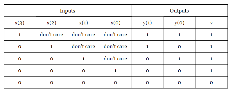
The Verilog code is:
module Prio_4_to_2
    (
    input wire [3:0] x,
    output wire [1:0] y,
    output wire v
    );

    assign y =  x[3] ? 2'b11 :
               x[2] ? 2'b10 :
               x[1] ? 2'b01 :
               2'b00;

    assign v = ( x[3] | x[2] | x[1] | x[0] ) ? 1'b1 : 1'b0;

endmodule
Lines 7‑10 showcase the nested conditional operator. Each condition is evaluated sequentially, giving higher priority to earlier terms—perfect for priority logic. The final assign for v uses a bitwise OR to indicate whether any input is high.
Simulation results from Xilinx ISE confirm the behavior (Figure 2).
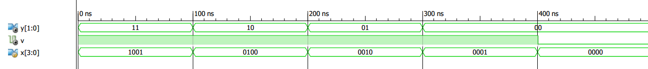
Figure 2. Xilinx ISE simulation of the priority encoder.
It is essential to note that the conditional expression is evaluated in order until a true condition is found; the corresponding value is then assigned. Consequently, this construct is best suited for priority networks (Figure 3) rather than balanced multiplexers (Figure 4).
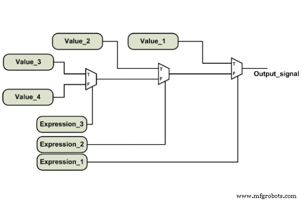
Figure 3. A priority network.
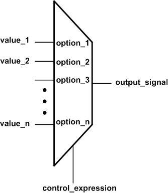
Figure 4. An n‑to‑1 multiplexer without input priority.
In a previous article, we discussed VHDL concurrent assignments; the concepts translate similarly to Verilog.
Verilog Procedural Statements
While assign and conditional operators suffice for many designs, the always block offers a more expressive, procedural approach. Inside an always block, statements execute sequentially and can include high‑level constructs such as if and case, mirroring the natural flow of human reasoning.
Example 2 demonstrates a basic always block used to implement a simple AND gate.
Example 2: “Always” Block Statements
The simplified syntax of an always block is:
always @(sensitivity_list)
begin
    sequential_statements;
end
The sensitivity_list specifies when the block should be re‑evaluated. For a purely combinational circuit, all input signals must appear in this list.
Consider the circuit in Figure 5, where the output changes whenever a or b toggles.
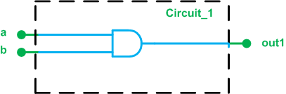
Figure 5. Circuit_1
The following always block implements the AND operation using a blocking assignment:
always @(a, b)
begin
    out1 = a & b;
end
Blocking assignments (=) update the left‑hand side immediately, whereas non‑blocking assignments (<=) delay the update until the end of the block. For combinational logic, it is safest to use blocking assignments to avoid unintended race conditions.
Because a procedural block cannot drive a wire, the output must be declared as reg, which may or may not infer a storage element. The complete module is shown below:
module Circuit_1
    (
    input wire a,
    input wire b,
    output reg out1
    );

    always @(a, b)
    begin
        out1 = a & b;
    end

endmodule
In summary, this article covered the conditional operator for compact truth‑table logic, nested operators for priority encoding, and the procedural always block for clearer combinational descriptions. Future posts will explore using always for sequential logic.
Embedded
- Verilog Basics: Designing Your First AND Gate
- Foundations of DC Circuits: Understanding Direct Current and Core Electrical Concepts
- Understanding AC Circuits: A Beginner's Guide
- Designing a Four‑Digit 7‑Segment Display with a Single Binary Encoder
- Crystal and Transistor Radio Circuits: From Basic Detectors to Integrated AM/FM Receivers
- Control Circuits: Fundamentals, Applications, and Best Practices
- C# Operators – Comprehensive Guide to Operators in C#
- C# Ternary Operator: A Concise Guide to Conditional Expressions
- Mastering Verilog Concatenation: A Practical Guide
- Verilog `ifdef: Conditional Compilation Explained