


Accelerating RTM Processes Using Heat‑Flux Sensors
Accounting for 3-5% of an aircraft’s weight, landing gear have long been targeted for weight reduction to improve aircraft efficiency. This has become even more critical with the imminent switch to energy- and emissions-reducing electric propulsion systems.
For example, Safran Landing Systems (Vélizy, France) will enable engines-off, electric taxiing via electric motors integrated into aircraft landing gear wheels, reducing NOx, CO2, CO and unburnt hydrocarbons emissions by 51%, 61%, 73% and 62%, respectively. This is a huge win for more sustainable aviation, but electric motors require power, and the batteries needed to supply that power are heavy.
Thus, the demand for lightweight landing gear structures seems a perfect fit for applying composites, except for one issue. “Because the landing gear is a single-load path structure, failure of a structural component could result in a serious emergency landing condition,” says Peet Vergouwen, technologist at GKN Fokker Landing Gear (Helmond, Netherlands). GKN Fokker Landing Gear has worked for more than a decade to demonstrate the technical feasibility of composite landing gear structures, including development of carbon fiber-reinforced polymer (CFRP) drag stay braces for the F-35 Lightning II. “Due to their criticality, landing gear structures are among the most conservative in commercial aircraft.” Hence, they have mostly been manufactured from high-strength metals.
That tide is beginning to turn, however. Clean Sky 2 is pursuing a 30% weight reduction, but via CFRP components in the HECOLAG (High Efficiency Composites LAnding Gear) project, for two applications. In the first application, a CFRP alternative was developed for the existing aluminum upper drag stay for the A350-1000 nose landing gear, originally developed and manufactured by Liebherr-Aerospace (Lindenberg, Germany). HECOLAG partners Royal Netherlands Aerospace Centre (NLR, Marknesse) and GKN Fokker Landing Gear have designed this CFRP drag stay to Liebherr requirements. Using in-house developed automated preforming technology, NLR has built functional prototypes of the CFRP drag stay, which were tested by GKN Fokker Landing Gear.
In the second application being evaluated by HECOLAG, NLR and GKN Fokker Landing Gear have also developed a CFRP lower side stay in conjunction with Safran Landing Systems for the electrified main landing gear. CW will report specifically on the overall HECOLAG project results later in 2021, but here, the focus is on the INNOTOOL 4.0 subproject, guided by topic manager GKN Fokker Landing Gear to advance highly automated production of CFRP landing gear structures using resin transfer molding (RTM). Specifically, INNOTOOL 4.0 seeks to demonstrate sensor-integrated tooling that will lead the way to smaller tools with less mass for faster production cycles, easier handling and reduced energy consumption, as well as increased automation for lower cost and composites 4.0-intelligent process control. The INNOTOOL 4.0 project is funded by the Clean Sky 2 Joint Undertaking under the EU’s Horizon research and innovation program under GAP No. 821261.
INNOTOOL 4.0 goals
The demonstrator for this second part of HECOLAG (see opening image) is more of a generic part, Vergouwen explains. “It is for demonstrating part design, simulation and manufacturing methodologies that will provide the performance, production rate and cost needed for single-aisle aircraft.” By the end of 2017, the HECOLAG consortium had defined the initial CFRP demonstrator part and production tool, analyzed tool thermal behavior and conducted performance trials. This large and complex product passed preliminary design review and reached a technology readiness level (TRL) of 4 later that year. “Based on the issues and lessons learned from that first demonstrator, we were searching for partners to develop RTM tooling technology to optimize and shorten the cure cycle,” says Vergouwen. A Clean Sky 2 Call for Partners was issued in 2018 and was awarded to the INNOTOOL 4.0 consortium, comprising equipment and automation supplier Techni-Modul Engineering (TME, Coudes, France) and resin injection specialist Isojet Equipements (Corbas, France). They began work in April 2019 and completed the initial milestones in March 2021.
“The composite part must be cost-competitive with forged steel and aluminum,” notes Vergouwen at GKN Fokker Landing Gear. “That is only possible with automation, enabling a very low number of labor hours and more affordable materials than current aerospace-grade, autoclave-cured CFRP.”
Thus, INNOTOOL 4.0 sought to integrate sensors into the RTM tooling that will monitor and manage the injection and cure processes including resin flow front detection. “The goal is to be completely automated — load the preform, push a button and the molding equipment will manage the temperature, pressure, vacuum and cure,” says Stéphane Besson, commercial director at TME. However, this is the first time that GKN Fokker Landing Gear and TME have worked with cure monitoring. “We have worked with temperature and pressure sensors before,” says Besson, “but not with sensors for resin flow and polymerization.”
The INNOTOOL 4.0 project’s initial milestones required TME and Isojet to deliver a sensor-equipped molding tool and injection system to NLR that would be used to produce demonstrator parts in March and April 2021. In parallel, TME would use an existing tool for the production of CFRP plates — sized 600 x 600 millimeters with thickness of 1-8 millimeters — modified with the same sensors for process control trials at their facility. “This is something you'd rather do on a small scale the first time rather than directly on a large tool with a high-cost part,” says Vergouwen. Thus, TME used a different tool, but the same sensors to show their capabilities and depth. With this testing complete, NLR would then reuse the main HECOLAG tool to produce a new round of CFRP demonstrators to further optimize process control on actual parts.
RTM production tool design
TME began production of the RTM tool design using CATIA V5 software by Dassault Systèmes (Vélizy-Villacoublay, France) for mechanical and electrical design, and ANSYS (Canonsburg, Pa., U.S.) for thermal and mechanical simulation. This tool would be paired with Isojet’s piston-based 1K-2K (for one- and two-part resins) system to inject Hexcel (Stamford, Conn., U.S.) HexFlow 2K RTM 6 and Solvay (Alpharetta, Ga., U.S.) 1K PRISM EP 2400 one-component, aerospace-grade epoxy resins at an injection pressure of up to 20 bar.
“The shape of this molding tool is very complex,” notes Besson, “combining varying thicknesses in the 3D dry preform with a closed, tubular shape. This creates complex thickness transitions, with issues around preform assembly, ply end accuracy, internal temperature gradients and resin shrinkage, as well as how to optimize the heating method and heating capacity of the internal mandrel to enable a short cycle time. To enable short cycle times, all elements of the tool must be simple to use, robust and allow rapid heating and cooling.” Even though the INNOTOOL 4.0 project briefly requested non-metallic mold solutions, a typical matched set of upper and lower steel molds was devised due to the pressures necessary to minimize wrinkles and ensure fiber alignment during forming.
The matched upper and lower molds and mandrel are heated and cooled. “The matched molds use an integrated water circuit while the mandrel is electrically heated,” explains Besson. “Water circulation provides quick heating and cooling to reduce the part cycle time and the electrical heating achieves the same in the mandrel where space is limited.”
“Another challenge was the number of parts in the mandrel,” says Besson. “Because of the complex shape and need to remove the mandrel after molding, it comprised six self-heating components and two support elements where the sensors pass through to control the internal temperature of the mandrel pieces. In use, these elements are assembled by hand with the help of a base support that guides the operator.” Work with an inflatable mandrel as a solution will be completed within the larger HECOLAG project, but that was not included in the INNOTOOL 4.0 subproject.
Heat flux sensors
TME initially planned to use dielectric sensors to monitor resin flow and cure (see “Combining AC and DC dielectric measurements for cure monitoring of composites”) but switched to heat flux sensors from TFX (Boncourt, Switzerland). “As we progressed in the development, we wanted sensors that allowed measurement without direct contact with the polymer and composite materials to be controlled,” explains Jorge Lopez Torres, project manager at TME. “The TFX sensors enabled this because they measure heat flux, which propagates through the materials.” He points out that this is basically the same measurement used in differential scanning calorimetry (DSC), a laboratory technique that analyzes a polymer or composite’s state of cure. Notably, TFX sensors and DSC testing both measure the heat released during polymerization/cure and result in a curve of heat flux versus temperature and time.
For TFX sensors, the temperature data comes from an internal temperature sensor within the heat flux sensors. Although dielectric sensors are similarly equipped with an internal temperature sensor, the two sensors are very different. “Dielectric sensors directly measure the polymer properties during cure,” explains TFX manager Dr. Fabien Cara. “Heat flux sensors do not give the material’s state at a given instant. However, measuring the heat generated during resin flow and polymerization provides a nice view on how the process is behaving and how repeatable the cure cycle is for each part produced. And like DSC, we need to see the whole curve of the curing process, but our ability to monitor cure is very reliable.”
Decades of experience
Founded as Thermoflux in 2000, TFX sensors have been used in trials at R&D centers and in industrial applications by more than 100 customers worldwide. “We began work with RTM more than 15 years ago,” says Cara, “first with BMW for automotive parts and also for the technical center now known as Institute de Soudure [(Saint-Avold, France)]. In 2006 and 2012, we started two large projects for monitoring the cure of aircraft engine fan blades made using RTM and 3D- woven preforms. Safran has a data acquisition system we developed for them in their composites lab near Paris. They can record up to 100 signals simultaneously [(heat flux, temperature and pressure]) and analyze these for curing and monitoring process cycles.” TFX has also worked with Hexcel in its lab at Les Avenières, France, to monitor quality and processing cycles with thermoset resins injected into dry preforms. TFX sensors were also used in a project with IRT-M2P (Porcelette, France) to demonstrate Compression RTM (Learn More). “Our sensors are very efficient for fast processes such as compression molding, including with SMC and BMC molding compounds,” notes Cara. “We also won a JEC Innovation award in 2016 with Huntsman Advanced Materials [(Basel, Switzerland)] for a development titled, ‘Structural epoxy parts with autoclave quality in less than 1 minute.’”
TFX has sensors for every type of composites molding process, based on the method of heat transfer to the sensor: conduction (RTM, compression and injection molding), convection (autoclave, oven) and radiation (filament winding, AFP). The sensors used in the INNOTOOL 4.0 project were conductive, designed for embedding within metal RTM molds. “They provide an exceptionally repeatable signal at a distance of up to 1 millimeter from the tool surface and composite material,” notes Cara.
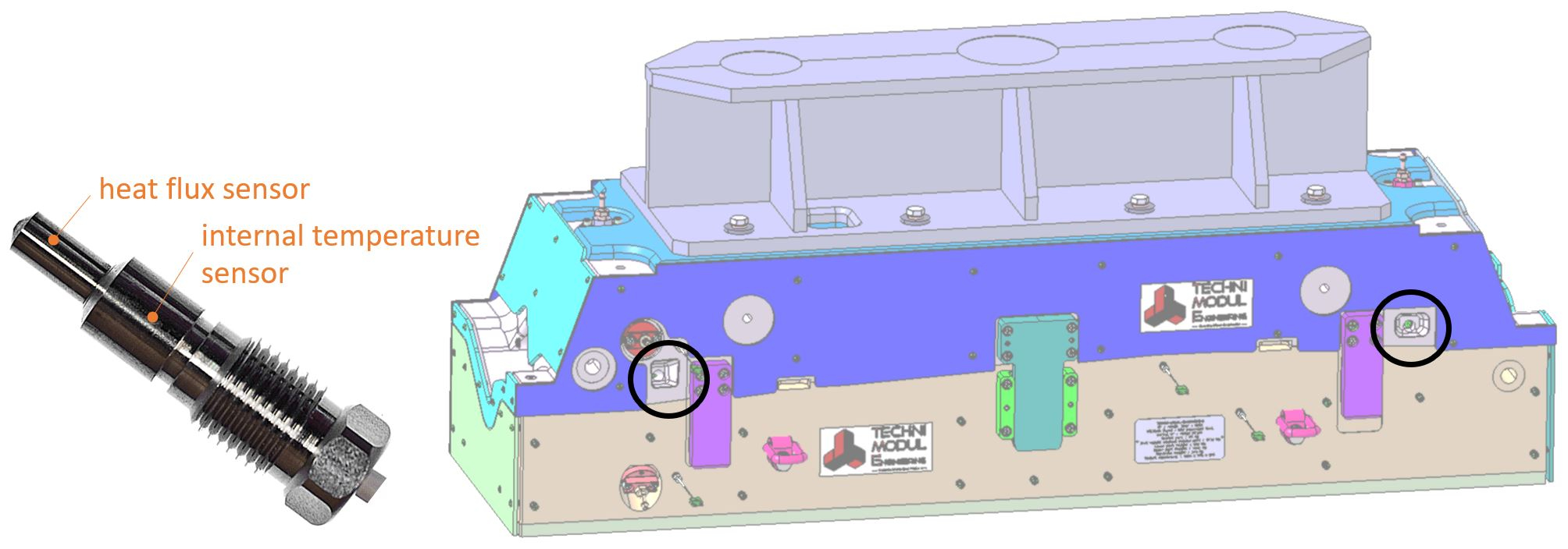
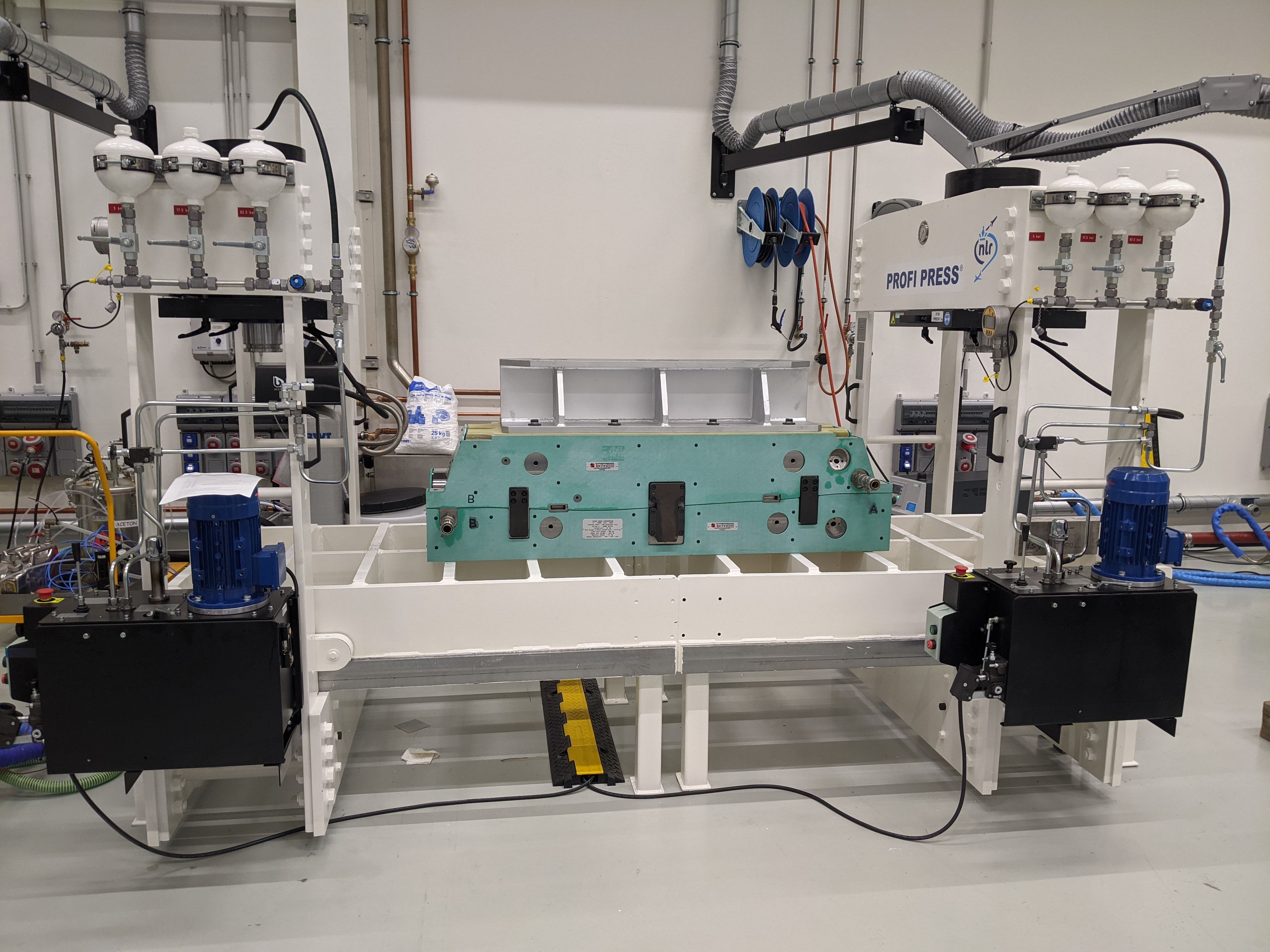
TME installed two TFX-191 sensors — one at resin entry and one at resin exit — into the upper mold of the matched production toolset that it then sent to NLR (Fig. 1, 2). NLR used this production tool to make HECOLAG demonstrator parts in March and April 2021. The TFX-191 sensors are for thick metallic tools.
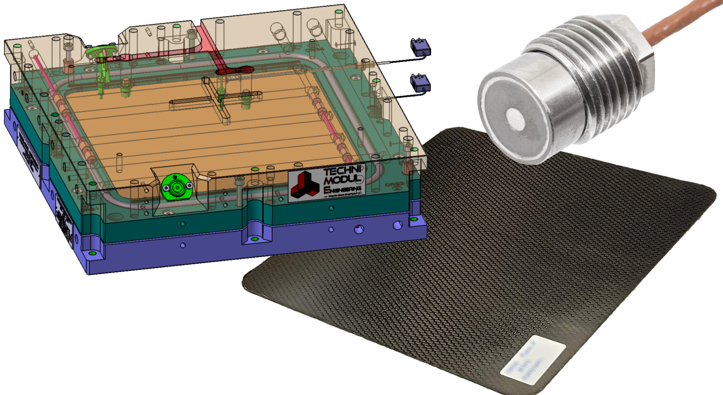
In parallel, TME took a smaller, in-house tool used for making sample CFRP plates and modified it with two TFX-224 sensors, which are shorter, for thinner tools (Fig. 3). This RTM plate toolset was then used to conduct sensor demonstration trials per the INNOTOOL 4.0 objectives described above. “These sensors are similar to what we used for Safran,” says Cara, “but are now improved to be much more compact and sensitive.” The sensors were placed near the center of the part and the resin exit. In addition to heat flux sensors, TFX developed and supplied two data acquisition systems — one delivered to Isojet and one used by TME for the CFRP plate trials.
INNOTOOL 4.0 test results
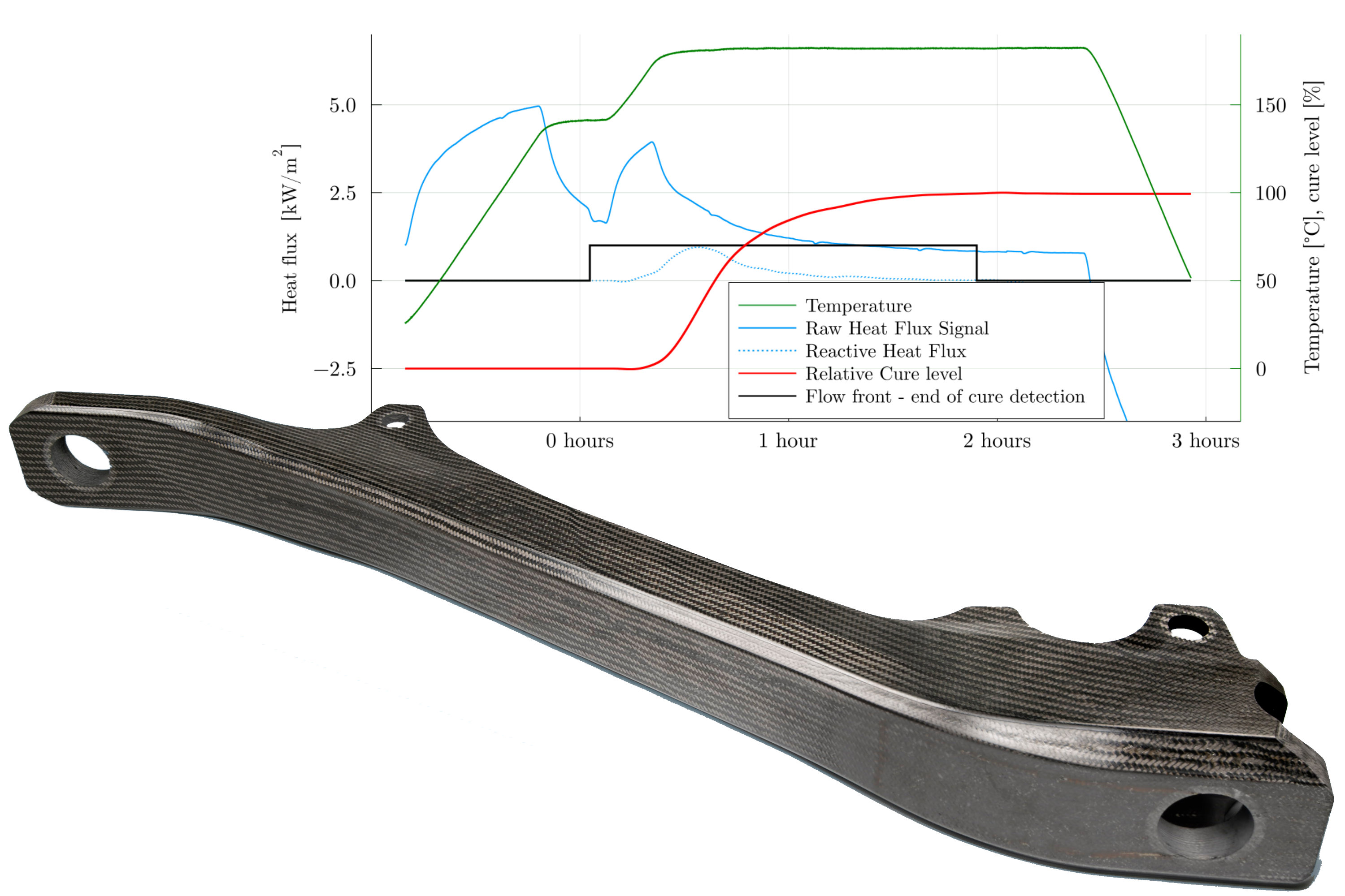
The trials TME conducted using its plate tool modified with TFX sensors tested two different resins — HexFlow RTM 6 and PRISM EP 2400 — as well as the influence of part thickness and overall cure time. “The sensors provided nice signals to monitor the cure cycle,” says Cara. “The team then analyzed the curing curves and showed that cure time for RTM 6 could be reduced by at least 30 minutes from the prescribed two-hour cure.”
This can be seen in the curve below, where t=0 hours is the onset of injection. Note, curing time begins when temperature reaches 180°C and end of cure corresponds to 99% of the relative cure level (see vertical axis at right). End of cure also coincides with raw heat flux stabilization.
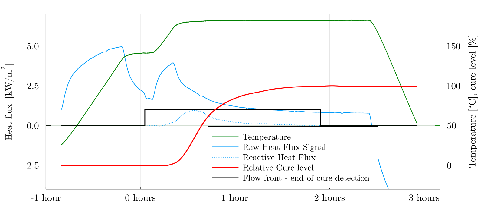
This was verified by cure state measurements of demolded parts using dynamic mechanical analysis (DMA), an alternative lab technique to DSC that measures glass transition temperature (Tg) for composites. “The DMA results confirmed that for RTM 6 resin, the Tg remains unchanged after 90 minutes of curing at 180°C,” he adds.
The effect of thickness was also investigated. “The first CFRP plates tested by TME in their sensor demonstration trials were less than 2 millimeters thick,” notes Cara. “These plates also had a high fiber volume (50-60%) and a slow cure cycle to prevent exotherm and potential issues with thermal stress and part quality. All of this is very normal for aerospace parts, but it means there is very little resin, and thus the amount of heat flux released by the resin reaction was small. So we were, in effect, looking for the needle of heat flux due to resin curing within an ocean of heating the tool and the part.”
In other words, as Cara explains, “Most aerospace RTM cure cycles involve injecting resin at one temperature and then ramping to cure at a second, higher temperature. Thus, when you finish injection, you heat up the tool to the cure temperature, which generates a large heat flux in the overall system.” However, as with DSC testing, the key to monitoring cure with heat flux sensors is to measure the heat released during polymerization/cure and display those measurements in a curve of heat flux versus temperature in the molding system and time. “So, we invented a method that helps us to subtract the baseline of heating the mold, and the conduction of that heat to the part, so that it is possible to identify the heat flux of the resin reaction.”
Thus, even though the process conditions in the initial thin plates were very challenging, says Cara, “we could still see the heat flux from resin reaction. However, by also making thicker parts, we were able to see exactly the difference in heat flux levels according to part thickness and this validated our cure monitoring in the thin parts.” Note, the curve above (also shown in the opening photo) was obtained using RTM 6 resin in a 3.2-millimeter-thick plate.
Results for resin flow front detection, however, were more problematic. “For the sensor near the exit, we could see flow very well, but not for the sensor near the center, where resin arrived very late,” says Cara. “Flow front detection with heat flux sensors requires the resin flow to produce a change in the local thermal field. This occurs when the resin is not at the same temperature as the preform.” He notes that ΔT greater than 0.1°C is sufficient for detection. “However, with the thin CFRP plate trials, the temperature was very even in the mold and the resin arrived very slowly. Thus, the thermal contrast was not enough to detect resin arrival versus the thermal noise in the overall system. The resin arrival at the exit, however, was faster due to runners [gaps between the preform and mold edge, see “Manufacturing the complex geometry parts of RAPM”] which helps to create a larger thermal contrast that was easier to detect and monitor.”
Cara suggests that this resin flow front monitoring could be improved with new active sensors that TFX has developed which use an integrated heating capability within the sensor. “This allows the sensors to help provide the thermal contrast necessary in parts and processes where it is inherently difficult,” he explains.
Extending composite process control capability
“We are happy with the work we have completed so far,” says Torres, “but this is just a first step. The goal is to use these heat flux sensors for managing composites processing in production environments.” This is possible, says Cara, by automatically sending a signal from the sensor system to the injection equipment based on resin arrival and to the press based on a zero slope in the cure curve. Torres adds that TME has process control systems for the injection machine and RTM press that manage temperature and pressure. “The next step,” he says, “is to integrate the TFX sensors into these control systems and manage the overall process from a laptop.” Cara notes that TFX sensors and data acquisition also work with pressure sensors (e.g., Kistler, Winterthur, Switzerland) to aid in this overall process control, and his company is developing a sensor that will measure heat flux, temperature and pressure in a single integrated device.
But is this process control affordable? Cara says the initial $10-30,000 investment for the monitoring system generally achieves a return in the development phase, reducing trial and error via improved process and part understanding. “The system then goes on to provide savings during production, reducing cycle time, ensuring repeatability and providing early detection of drifts or non-conformities.”
At GKN Fokker, Vergouwen believes that once the ability to reduce cycle time and improve cost is proven, “then it is possible to imagine composites in not just the type of landing gear component demonstrated in the INNOTOOL 4.0 and HECOLAG projects, but all types of parts. That would open up our design space and enable us to push the boundaries of lightweight landing gear even further.” Besson sees an even wider application: “This type of process control can be developed for all kinds of molds and composite parts.”
Resin
- Comprehensive Guide to Sensor Types and Circuit Diagrams
- Analog vs Digital Sensors: Types, Applications, and Practical Examples
- Achieving High-Precision Temperature Measurements with Advanced Silicon Sensors
- Build Sensor‑Driven Audio Effects with the Satellite CCRMA Kit
- Measuring Analog Sensors on the Raspberry Pi with a Single GPIO Pin
- IoT Sensors Revolutionize Air Pollution Monitoring and Public Health
- Safeguard High-Value Sensors with ePTFE: Proven Protection for Harsh Environments
- Landing Gear Component Manufacturing: Insights from Aerospace & Defense Leaders
- Harmonic Drive Gear Reduction: Precision and Efficiency
- Accelerate Production with the Motoman SSA2000 High‑Speed Welding Robot