


Achieving Smooth Ball Bearing Performance in FDM Parts with Insight Custom Groups
When a Direct Digital Manufacturing (DDM) project demands specific functionality beyond static end‑use parts, one common requirement is the integration of ball bearings within FDM housings.
Ball bearings are prized for their smooth sound and feel. In conventional machining or casting, this smoothness is inherent; however, when a bearing sits on a raster‑generated surface from FDM or DDM, the roughness can give the impression of a damaged assembly.
The real challenge is to fabricate a bearing housing that sounds and feels as smooth as a machined part—without resorting to post‑processing finish steps.
In traditional FDM, the floor that the bearing rides on is composed of rasters—layer‑by‑layer prints that create an uneven surface, often referred to as the “Green Flag” finish.
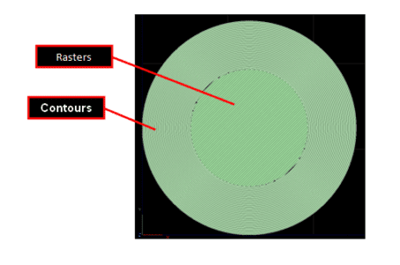
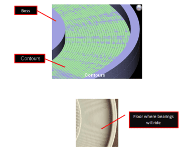
In this project, parts were printed on a Fortus 380mc using ASA filament. The resulting STL files were processed in Insight™ software, which offers advanced editing tools such as Custom Groups. Custom Groups can convert a floor’s raster pattern into a series of contours, producing a much smoother surface for the ball bearings. Contours are material layers that follow a region’s outline, whereas rasters fill the interior from edge to edge.
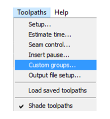
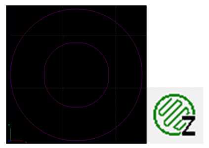
Custom Groups are accessed through the Toolpaths menu on the main interface.
Once selected, the Custom Group panel appears on the right side of the screen.
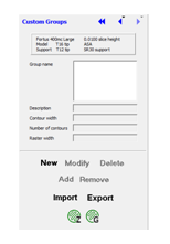
Click “New” and rename the group to a meaningful title—for example, “BearingFloor.”
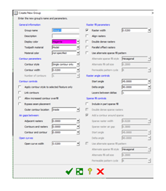
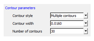
Under Contour Parameters, change the style from the default “Single Contour” to “Multiple Contours.” Set the contour width to the minimum allowed by the .010 mm slice thickness, and specify 30 contours.
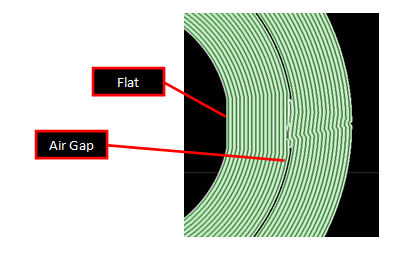
Next, select the layer—or group of layers—then click “Add.” The chosen layers turn magenta and will not have a toolpath. Preview the toolpath by clicking the Z icon at the bottom right.
The preview reveals design‑induced issues: a flat internal face keeps the base from spinning, but it also creates an air gap right under the bearing. This gap causes a slight wobble and a single raster that acts as a brake every 90 degrees.
I tested multiple combinations of contour width and number, always favoring the smallest width to maximize smoothness. The key was to eliminate the air gap.
Another consideration is wall thickness. Because this is a DDM part, the rule of even wall thickness does not apply. The best solution is to revise the CAD model rather than editing in Insight.
After revising the model in SOLIDWORKS, the layer now has a solid raster and is ready for a new Custom Group. I maintained the desired contour width and increased the number of contours.
The revised configuration delivers satisfactory results: the contours are at the minimum for my .010 mm extruder tip, resulting in a smoother and quieter ball‑bearing rotation. The center rasters are acceptable because the boss will cover them.
Although the finish isn’t identical to machined or cast parts, the processed ball‑bearing floor is a success. Sound quality improves dramatically, eliminating the rough noises of the original rasters and reassuring customers that the assembly is intact. The feel is smoother, with significantly less resistance. When weight is added, sound, feel, and function collectively grant the project the green light.
Without Custom Groups, this component would never reach its full potential. FDM parts would remain in the realm of “Traditional” printing. Insight Software empowers us to push beyond that boundary—creating a process we can control and continually refine.
Direct Digital Manufacturing holds vast promise and reward. There is still much to learn and improve upon. I plan to finish these parts and will share the final results once completed.
Tags: 3D Printers, AMG, Ball Bearings, Custom Groups
3D printing
- Understanding Ball Bearing Races: Structure, Function, and Types
- Ball Bearings: Evolution, Manufacturing, and Quality Assurance
- Application Spotlight: 3D Printing Revolutionizes Bearing Design and Production
- Formlabs Unveils Advanced 3D Packing for Fuse 1, Cutting Print Costs by Up to 46%
- 3D‑Printed Custom Fuel Injector Grippers: Boosting Pick‑and‑Place Efficiency
- Preloading Ball Bearings: Boost Precision, Reduce Noise, and Enhance Performance
- Sealing Solutions for Industrial Bearings
- Phenolic Plastic: The Superior Choice for High-Performance Bearings
- Mastering Custom CNC Machining: The Power of Jigs & Fixtures
- Understanding Ball Bearing Load Capacity and Friction Reduction