


Revolutionizing 3D Printing: Precise Joinery for Effortless Assembly
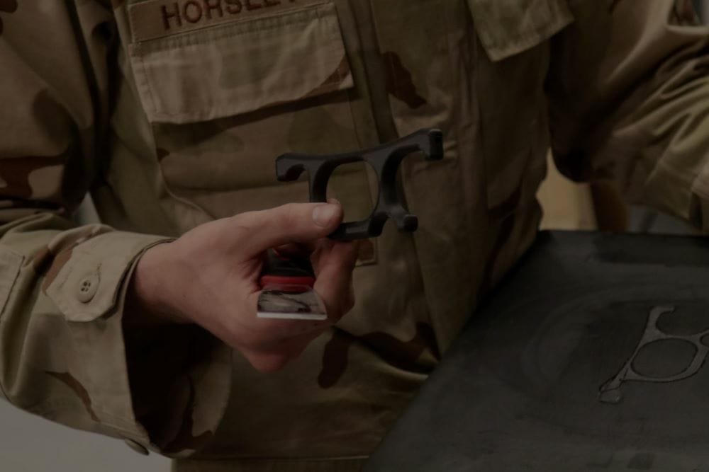
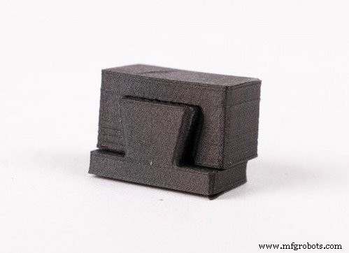
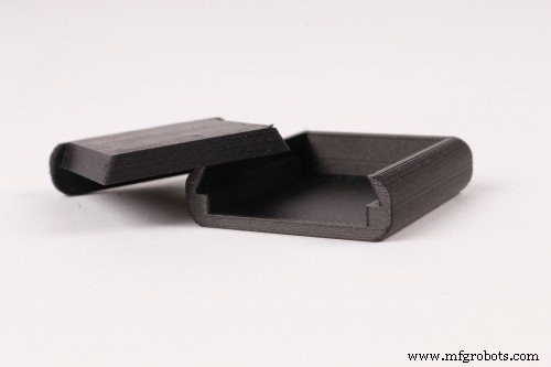
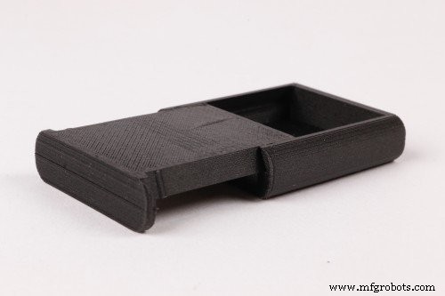
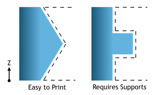
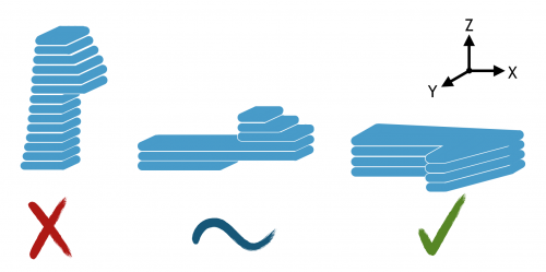
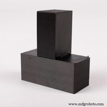
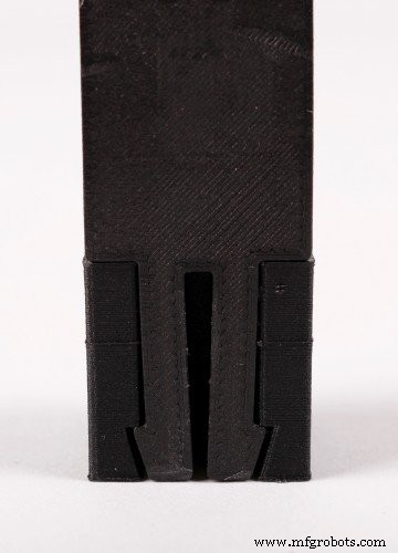
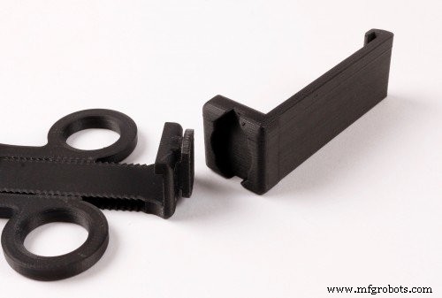
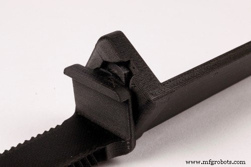
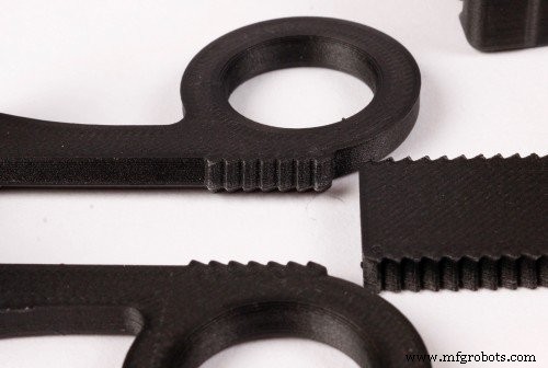
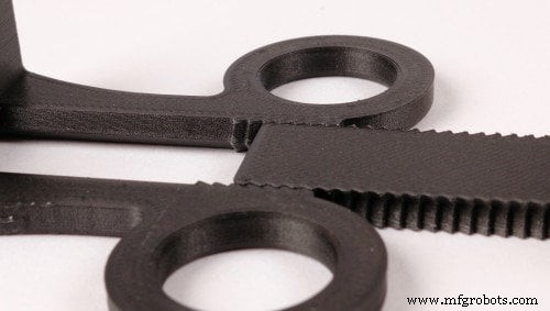
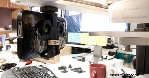
Read our newest customer success story about a major training base for the U.S. Army. With the launch of Onyx, our micro‑carbon‑fiber‑infused nylon filament, we’ve been testing its capabilities. The filament’s exceptional surface finish and dimensional stability make it ideal for creating precise joinery, inspiring this guide to robust 3D‑printed connections using a desktop printer. Joinery is a term from woodworking that describes the art of joining two pieces of material by geometrically constraining them. Strong joinery offers reliable connections with minimal fasteners, simplifying assembly. Traditional joinery can be complex and time‑consuming, whereas bolts and screws rely on simple holes and off‑the‑shelf fasteners. 3D printing excels at producing intricate geometries without a price premium. FDM’s layer‑based process limits material properties, so designers must rethink geometry to reduce assembly complexity and cost. By borrowing joinery concepts from woodworking and injection molding, you can create printable interfaces that harness 3D printing’s geometric freedom. While right angles are the default in machining, 3D printers treat dovetails and straight walls the same. Dovetails add a third degree of freedom, enabling sliding or lock‑in joints without fasteners. This principle works for T‑joints, sliding assemblies, and more. The sliding box example demonstrates how a dovetail‑like constraint can be achieved with a simple angled plate. It slides cleanly, features a detent for snap‑closure, and prints on the Mark Two without supports, delivering a great fit on the first attempt. Angled geometry also aids 3D printing. A sideways V profile can constrain motion in ways that are hard to machine but trivial to print. Conversely, classic tongue‑and‑groove joints create overhangs that compromise dimensional accuracy, so they should be avoided if possible. Snap fits are a cost‑effective joining strategy in injection molding, exploiting plastic’s elastic deformation. They translate well to FDM when oriented correctly: printed in the XY plane to avoid shear along the Z axis. Thin cross‑sections reduce bending moments, but the orientation matters. Printing a snap fit upright places tensile forces across layer boundaries, increasing failure risk. On its side, the snap fit’s cross‑section lacks layer planes, improving predictability. For larger snap fits, printing sideways also allows fiber routing into the tooth, fully utilizing composite strength. Snap fits can take many forms depending on the application. Because FDM is unconstrained by mold geometry, you can experiment with placement and geometry before finalizing. Rapid prototyping lets you iterate through variations quickly. To illustrate sliding fits and snap mechanisms, I designed a phone holder that attaches to the Mark Two’s hood and secures phones 2.5–4 inches wide. The holder features only three parts and two interfaces. The first interface is a twisting joint that functions as a hinge, using complementary angles for a clean sliding fit. The second interface is a linear ratchet with angled walls and teeth, setting the holder’s width. This design would be difficult to machine but prints quickly and reliably. Joinery requires careful tolerance design. On the Mark Two, a 0.08 mm clearance between walls (0.16 mm diameter) typically yields a reliable sliding fit. If a surface relies on support material, increase the clearance to ~0.15 mm. Because printed parts can vary, always prototype and test to confirm the desired fit. Designing with joinery in mind can simplify your models and improve fit. Share your successful joints with us on Twitter @MarkForged.U.S. Army Case Study
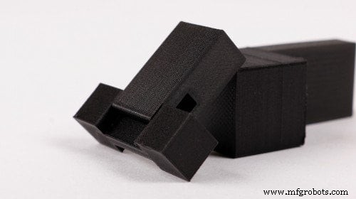
Dovetails
Check out our Composites Design Guide
Snap Fits
Request a free sample part
Putting it Together: Phone Holder

A Note on Tolerances
3D printing
- 3D‑Printed Drone Enables Rapid, Cost‑Effective Data Collection in Antarctica
- 12 Expert Tips for Designing PCBs That Assemble Perfectly
- Top 10 FAQs on Printed Circuit Board Assembly – Expert Insights
- 7 Expert Strategies for Crafting Comprehensive PCB Assembly Documentation
- 13 Proven Testing Techniques for PCB Assembly Quality
- Complete Guide to Printed Circuit Board Assembly (PCBA)
- Mastering PCB Assembly: From Blueprint to Finished Product
- Enhancing PCB Assembly: Advanced Bottom-Filling Technologies
- Innovations Driving the Future of PCB Assembly
- Silencio: A 3D-Printed Tactile Poetry Book for Sighted and Blind Readers