


Designing a 3‑D‑Printed Tesla Turbine – Part 1: Recreating the Housing with Markforged
Introduction
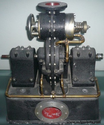
Welcome to the first installment of our two‑part series on retrofitting a Tesla turbine with Markforged components. We’ll walk through every step—from concept to design to final print—using proven techniques from earlier posts. By the end of this series, you’ll see a fully functional Tesla turbine, spun by a Markforged‑printed housing that’s lighter, stronger, and ready for extreme speeds.
What Is a Tesla Turbine?
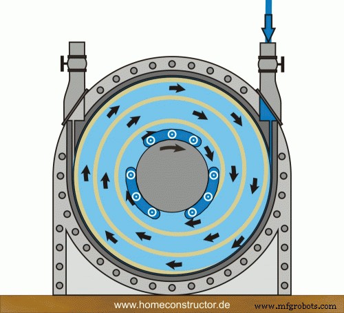
A Tesla turbine, patented by Nikola Tesla in the early 1900s, is a blade‑less, centripetal flow device. Fluid enters tangentially to a series of smooth, parallel discs, and the viscous interaction between fluid and disc surfaces drives rotation. Unlike conventional bladed turbines, the Tesla design relies on boundary‑layer adhesion, allowing for a much simpler geometry and potentially higher efficiencies.
Tesla claimed up to 90% efficiency, but real‑world tests found about 40%—still far above the 25‑30% range typical of bladed turbines. The main limitation was the extreme rotational speeds (9,000–36,000 rpm) required, which caused blade warping and mechanical failure. Today, Tesla turbines are mostly educational toys, but their elegant simplicity continues to inspire engineers.
Reimagining the Turbine with 3‑D Printing
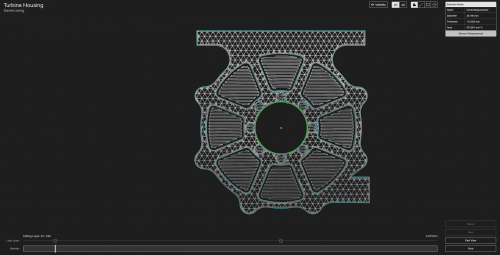
We began with a proven Olin College design that splits the machine into three primary assemblies: a shaft/rotor system, a bearing housing, and a turbine housing. The bearing and turbine housings mate with a tight metal locating feature and eight mounting screws, while the shaft is fully constrained by the bearing housing.
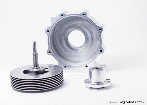
Most components are straightforward to machine: CNC‑milled aluminum housings, turned steel shafts, and water‑jet cut spacers. Because the turbine’s geometry is simple and the required tolerances are modest (<0.001”), we saw an opportunity to replace the heavy aluminum housings with lightweight, high‑strength 3‑D printed parts without sacrificing performance.
Turbine Housing Requirements
- Mesh Integrity: The housing must mate perfectly with the bearing housing. A clearance of +0.001″/−0.001″ on the locating feature eliminates vibration that could otherwise destroy the turbine at high speeds.
- Mounting: Sixteen tapped holes—eight on the rear for the bearing housing, eight on the front for a polycarbonate cover—must be precisely positioned to maintain structural integrity.
- Blade Clearance: A very tight clearance fit between the housing cavity and the blades ensures maximum energy transfer and minimizes efficiency loss.
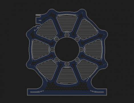
Design and Fiber Routing
We began by performing unit tests on the CAD model to verify tolerances. The tests revealed that undersizing the bore by roughly 0.002″ in CAD yields the required +0.001″ fit when printed. We also replaced all tapped holes with heat‑set insert cavities to guarantee reliable fasteners in the polymer matrix.
To reinforce the structure, concentric carbon‑fiber rings were routed throughout the part in Eiger. The back wall, which bears the majority of load, received a full complement of rings, while each outer wall layer incorporated a single ring. This strategy boosts hoop strength with minimal material, keeping the part lightweight.
Dimensional Verification
Although the turbine body could fit on a Mark Two, we chose the Mark X for its laser‑based dimension verification capability. Two laser scans were configured: one to inspect the bearing‑housing mating surface and another to verify the cavity diameter. During printing, each scan was checked in Eiger, confirming a dimensional error of only 0.0004″—well within tolerance.
Next Steps
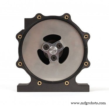
After the print finished, we installed the heat‑set inserts and bolted the aluminum bearing housing. The complete assembly weighed just 170 g compared to the 570 g aluminum counterpart—a reduction of 70% in mass. With the housing validated, we proceeded to design and print the bearing housing, which will be detailed in Part 2.
Read Part 2 of this series for the bearing housing design, and follow us on Facebook, Twitter, Instagram, and LinkedIn for more updates.
3D printing
- In‑Process Inspection: Elevating 3‑D‑Printed Part Quality
- Revolutionizing Production: Markforged’s 3D‑Printed Spool Dispenser Innovation
- Optimizing the IRIS+ Drone: Lightweight, Durable Arms with Onyx 3D Printing
- Weekly 3D‑Printed Highlight: Kevlar‑Reinforced Pliers
- Skateboard Part 1: Building Durable 3D‑Printed Wheels
- Professional Guide to Finishing and Painting 3D Printed Parts
- Master 3D Printing: Part 1 – Unit Tests & Tolerances for Accurate, Cost‑Efficient Builds
- Designing a 3D‑Printed Tesla Turbine – Part 2: Bearing Housing Development
- Guaranteeing Dimensional Accuracy in 3D Printed Parts
- Enhancing the Strength of 3D Printed Parts: Proven Techniques