


Automotive Alternator: Building a Three‑Phase Generator for Hands‑On Learning
Project Parts and Materials
- Automotive alternator (one required, but two recommended)
Used alternators can be sourced cheaply from wrecking yards, where many units are already removed for convenience. A new alternator is not necessary; a well‑conditioned used unit delivers the same performance for this experiment.
I recommend selecting a Delco‑Remy alternator, which powers many GM vehicles (GMC, Chevrolet, Cadillac, Buick, Oldsmobile). This model has remained virtually unchanged since the early 1960s, making it abundant in salvage yards and straightforward to disassemble.
With two alternators, you can turn one into a three‑phase generator and the other into a motor—the conversion steps are identical.
Cross References
Lessons In Electric Circuits, Volume 1, chapter 14: “Magnetism and Electromagnetism”
Lessons In Electric Circuits, Volume 2, chapter 10: “Polyphase AC Circuits”
Learning Objectives
- Understand the principles of electromagnetism and induction
- Explore the construction of real electromagnetic machines
- Apply knowledge of three‑phase windings in practice
Automotive Alternator Schematic Diagram
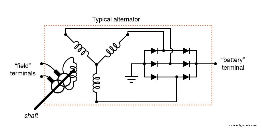
An automotive alternator is a three‑phase generator that incorporates a six‑diode rectifier. When the pulley (or sheave) driven by the engine’s crankshaft turns, a rotating electromagnet spins past a stationary Y‑configured set of stator windings.
The rotor is an electromagnet rather than a permanent magnet, allowing the magnetic field strength to be tuned with a small DC input. This design keeps the output voltage stable regardless of shaft speed.
The field coil receives power through copper slip rings and carbon brushes, which are kept in place by spring pressure. Many alternators include an onboard regulator that switches the battery on and off to control the field coil; if present, this regulator can be removed to simplify the experiment.
When the regulator is removed, leave the brush terminals accessible so you can supply the field coil with DC while the alternator remains fully assembled.
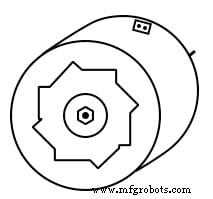
Automotive Alternator Illustration
Experiment Instructions
Start by consulting the service manual for your specific alternator model. The instructions below are generic and may need adaptation for other brands.
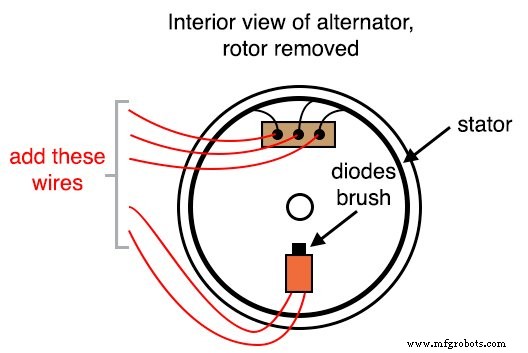
Because the manufacturer’s terminals are not suited to our experiment, you’ll need to create custom connections. Carefully disassemble the alternator and locate the terminals that feed the two carbon brushes. Solder a pair of 20‑gauge wires to these terminals, routing the leads through vent holes to avoid interference with the rotor.
Next, identify the three stator terminals that connect to the diode bridge. Solder 18‑ or 20‑gauge wires to each of these terminals and thread them out of the case. Use the largest practical gauge, as these conduct the full line current.
For reliability, attach ring‑lug terminals to your wires and secure them beneath the original terminal nuts. This ensures a robust connection to the diode block and simplifies future disassembly.
Re‑assemble the alternator, making sure the brushes are retracted to prevent contact with the rotor during operation. Delco‑Remy units often provide a small access hole; a paper clip or thin wire can hold the brushes back against the spring tension during reassembly.
After confirming that the shaft turns smoothly, connect the field leads to a 6‑V battery and attach a voltmeter to any two of the three line terminals:
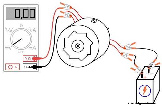
With the meter set to DC volts, gently spin the shaft. The reading should oscillate between positive and negative values, demonstrating the production of AC. Switching the meter to AC volts and repeating the test at different speeds will illustrate the relationship between mechanical input and electrical output.
Short any two of the three line wires and spin the alternator again. You will notice increased resistance to rotation—this is the mechanical load imposed by the electrical short circuit.
Now power the field coil with 12 V DC and repeat the DC, AC, and short‑circuit tests. Compare the results to those obtained with 6 V; higher field voltage will raise output voltage and increase load torque.
Attach a polarity‑insensitive load, such as a small incandescent lamp, to the three line terminals. Wrap a length of rope around the pulley and spin the alternator rapidly; the lamp should light, confirming that the alternator can drive a real load.
If you have a second alternator, follow the same wiring steps to prepare it as a motor. Connect the line terminals of the first alternator to the corresponding terminals on the second. Power the field coil of the first alternator from a 6‑V battery, and short the field coils of the second to create an induction motor.
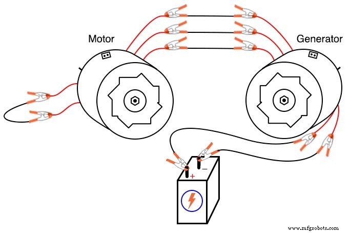
Spin the generator and observe the motor’s shaft. Reversing any two line connections will change the phase sequence, altering the direction of the motor’s rotation.
Alternatively, connect the motor’s field coil to the same 6‑V battery as the generator’s. The motor now operates as a synchronous motor, with the rotor locked to the rotating magnetic field.
Take Your Modified Alternator to the Next Level
For those with metal‑working skills, you can mount the alternator on a bicycle to create a pedal‑powered generator. The design I used connects the alternator’s pulley to the rear wheel via a long V‑belt, which also supports the rear of the bicycle and maintains tension while riding.
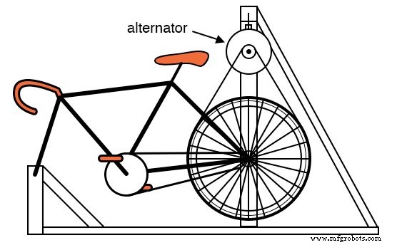
The generator is supported by a steel frame—2‑inch square tubing was used here, but a wooden frame would also work. The setup functions as a practical exercise machine and is inexpensive to build.

Three 12‑V “RV” lamps serve as a load, controlled by switches mounted on the front of the bicycle. By rectifying the three‑phase output, the alternator can power its own field coil, eliminating the need for a battery once the system is up and running. An initial DC source is still required to energize the field coil at startup.
RELATED WORKSHEET:
- AC Generator Theory Worksheet
- Polyphase Power Systems Worksheet
Industrial Technology
- Automotive Shop Safety Rules: Expert Guidance for Technicians
- Understanding the Alternator: How It Powers Your Car and Signs of Failure
- What Is an Automotive Oscilloscope? – A Technician’s Essential Diagnostic Tool
- The Role of an Automotive Service Manager: Duties, Career Path, and Compensation
- Revolutionizing Automotive Manufacturing: The ROI of Robotics
- Elevating Quality Standards in Automotive Manufacturing: Best Practices & Compliance
- Safeguarding Alternators: Comprehensive Fault Protection Strategies
- Choosing the Right Automotive Injection Molding Process for Optimal Quality
- Essential Guide to Alternators: How They Charge Your Car's Battery
- ABB Automotive Robots: Leading Automation Solutions for the Auto Industry