


Understanding Normal Positions and Contact Sequences in Process Switches
In process automation, a switch’s “normal” position is the state it occupies when no external force is applied – the position it would be in when mounted on a shelf, ready for operation.
Switch contacts are engineered to either close (create continuity) or open (interrupt continuity) when actuated. The way a contact behaves when it is unactuated defines its normal state:
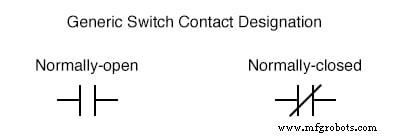
- Normally Open (NO) – the contact is open in the unactuated position. When the switch is actuated it closes, completing the circuit.
- Normally Closed (NC) – the contact is closed in the unactuated position. Actuation opens the circuit.
For switches equipped with a spring‑return mechanism, the direction the spring pushes the contact when no load is applied is called the “normal” direction. Consequently, a spring‑return NO switch will sit open on the shelf, whereas a spring‑return NC switch will sit closed.
Normal State of Process Switches
Process switches sense a physical variable – speed, pressure, temperature, level, flow – and change state when that variable deviates from a setpoint. Their normal state is simply the value the variable would have when the system is at rest, uninstalled or idle.
- Speed switch – shaft stopped
- Pressure switch – zero applied pressure
- Temperature switch – ambient room temperature
- Level switch – empty tank or bin
- Flow switch – no liquid flow
It is crucial to distinguish the switch’s inherent normal state from how it is used in a particular process. For example, a low‑flow alarm in a cooling‑water circuit may use a normally‑closed flow switch so that the alarm activates when flow drops. In normal operation the contacts are pulled open; a loss of flow returns them to their closed, “normal” state, completing the alarm circuit.
Schematic Symbology
Control schematics represent NO and NC contacts with distinct symbols to avoid confusion. A normally‑open contact is shown as two parallel lines that do not touch; a normally‑closed contact has a diagonal line bridging the pair.
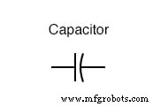
In the generic representation, the symbol is immediately annotated with the switch type (e.g., “Pressure Switch – NC”). Capacitors, even non‑polarized ones, are depicted with the standard capacitor symbol to differentiate them from NO contacts.
Multiple‑Position Selector Switches
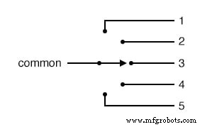
Selector switches control a common contact that can connect to several stationary contacts. Their operation hinges on the sequence of breaking and making connections as the selector is moved.
The most common arrangement is break‑before‑make: the contact first opens the current circuit before closing the next one. This guarantees that no overlap occurs, which is essential in many safety‑critical applications.
When an uninterrupted connection is required, a make‑before‑break design is employed. The moving contact bridges two positions simultaneously, so that the common wire is never fully disconnected during the transition. This configuration requires that the load tolerate brief overlap between adjacent throws.
Key terminology:
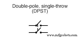
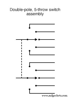
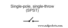
- Pole – number of moving contacts.
- Throw – number of stationary contacts per moving contact.
- Single‑pole, five‑throw (SP5T) – one moving contact, five stationary contacts.
- Double‑pole, five‑throw (DP5T) – two identical SP5T units mechanically linked.
Common switch notations (with abbreviated designations) include:
— and others shown in the original figures.
Key Takeaways
- The normal state of a switch is its unactuated position when stored.
- NO contacts are open in normal; NC contacts are closed in normal.
- Process switches’ normal condition reflects the idle or rest state of the measured variable.
- Selector switches can be configured as break‑before‑make or make‑before‑break, depending on the application.
- Pole and throw terminology describe the number of moving and stationary contacts.
For deeper insight, consult related worksheets: Time‑Delay Electromechanical Relays, Switches, and Basic Electromagnetic Relays.
Industrial Technology
- Process‑Actuated Switches: How They Work and When They Change State
- Designing Reliable Switch Contacts: Materials, Types, and Protection Strategies
- Eliminating Contact Bounce in Mechanical Switches
- Mastering C Control Flow: Break and Continue Statements Explained
- Mastering Python Loop Control: break & continue
- Step-by-Step Guide to Wiring a GFCI Combo Switch and Outlet: Diagrams & Installation Tips
- Professional Wiring Guide for Combo Switch/Outlet Devices – Diagrams & Installation Tips
- Touch Switches Explained: Types, Functions, and How to Build One
- CD4066 Quad Analog Switch: Key Features, Operation, and Practical Uses
- Benefits & Drawbacks of 3D Printing in Mold Fabrication