


High‑Pass Filters: Design, Function, and Practical Applications
A high‑pass filter performs the inverse of a low‑pass filter: it permits high‑frequency signals to pass while attenuating low‑frequency components. The two most common implementations—capacitive and inductive—mirror their low‑pass counterparts but with opposite impedance behaviors.
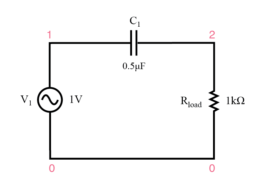 Capacitive high‑pass filter.
The Capacitor’s Impedance
In a capacitive high‑pass circuit, the capacitor’s impedance increases as frequency falls (see the plot below). This high series impedance effectively blocks low‑frequency energy from reaching the load.
capacitive highpass filter
v1 1 0 ac 1 sin
c1 1 2 0.5u
rload 2 0 1k
.ac lin 20 1 200
.plot ac v(2)
.end
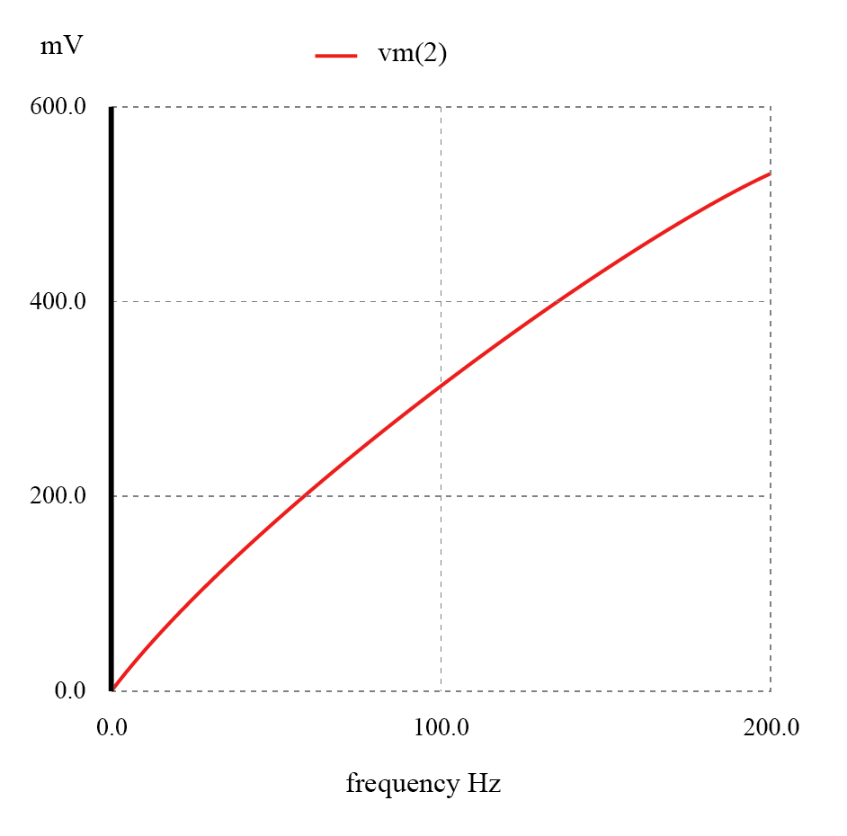 The response of the capacitive high‑pass filter rises with frequency.
 Inductive high‑pass filter.
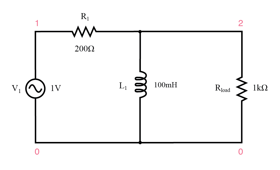
The Inductor’s Impedance
An inductive high‑pass filter behaves oppositely: the inductor’s impedance falls with decreasing frequency, providing a low‑impedance shunt that shorts out low‑frequency signals before they can drive the load resistor. Most of the voltage is then dropped across the series resistor R1.
inductive highpass filter
v1 1 0 ac 1 sin
r1 1 2 200
l1 2 0 100m
rload 2 0 1k
.ac lin 20 1 200
.plot ac v(2)
.end
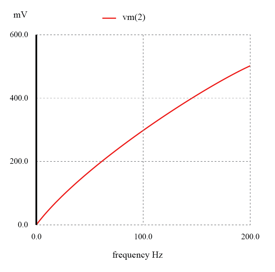 The response of the inductive high‑pass filter rises with frequency.
In practice, the capacitive design is often preferred because it requires only a single reactive component and offers superior purity; inductors tend to suffer from skin effect and core losses at high frequencies.
Cutoff Frequency
Like all first‑order filters, a high‑pass filter has a characteristic cutoff frequency, fc, where the output equals 70.7% (1/√2) of the input. For a capacitive high‑pass circuit the standard formula applies:
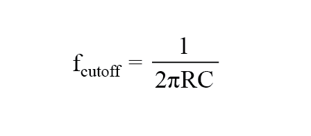
In the example above, the only resistance present is the load resistor (1 kΩ), so that value is used in the calculation.
Application of High‑Pass Filter
Consider a stereo system: a series capacitor on the tweeter forms a high‑pass filter, blocking low‑frequency bass energy from wasting power on a speaker that cannot reproduce it. Conversely, a series inductor on the woofer acts as a low‑pass filter, protecting the bass driver from high‑frequency distortion. The mid‑range speaker receives the full audio spectrum. For a more refined allocation, a band‑pass filter can be used to route the mid‑range frequencies exclusively to the mid‑range driver.
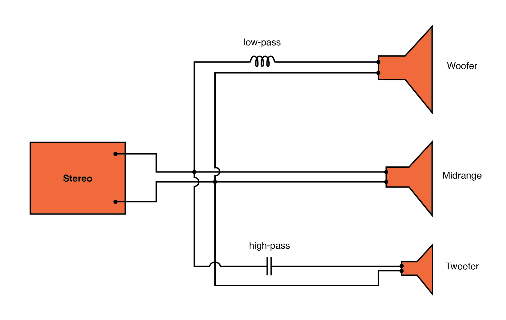 High‑pass routes highs to the tweeter; low‑pass routes lows to the woofer.
In a complete stereo system, six drivers are employed: two woofers, two mid‑ranges, and two tweeters, each fed by appropriate filter networks.
REVIEW:
- A high‑pass filter eases the passage of high‑frequency signals while attenuating low‑frequency content.
- Capacitive high‑pass designs insert a capacitor in series with the load; inductive designs add a series resistor and a parallel inductor, creating a low‑impedance shunt for unwanted frequencies.
- The cutoff frequency marks the point where the output equals 70.7% of the input; above this point the output improves, below it the signal is attenuated.
RELATED WORKSHEETS:
- Active Filters Worksheet
- Passive Filter Circuits Worksheet
Industrial Technology
- Understanding Filter Circuits: From Audio to Power Conditioning
- Low‑Pass Filters: Principles, Designs, and Practical Applications
- Band‑Pass Filters: Design, Implementation, and Practical Tips
- Band‑Stop Filters: Design, Twin‑T Implementation, and Notch Frequency Analysis
- Resonant Filters: Designing Band‑Pass and Band‑Stop Circuits with LC Resonance
- Ceramic Filters for Molten Metal Casting: Design, Production, and Market Outlook
- Schaffner Launches Advanced FN 9262/9266 RFI Filters with IEC C14 PEMs for Medical & Consumer Applications
- Why Prefilling Fuel Filters Damages Equipment & How to Avoid It
- A Complete Guide to Filter Types in Signal Processing
- Key Factors in Choosing the Right Compressed Air Filter