


Band‑Pass Filters: Design, Implementation, and Practical Tips
How to Create a Band‑Pass Filter
In many electronic systems, only a specific range of frequencies must pass through a signal chain. A band‑pass filter lets precisely that band slip through while rejecting all lower and higher frequencies. By combining a low‑pass and a high‑pass stage, we obtain a single filter that satisfies this requirement.
Below is a system‑level block diagram illustrating the concept:
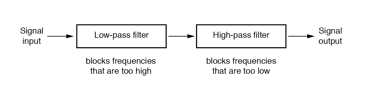
System‑level block diagram of a band‑pass filter.
Design a Band‑Pass Filter Using Capacitors
When the two stages are wired in series, the resulting circuit only passes frequencies that are neither too low nor too high. Here is a typical schematic built with passive components, and the corresponding frequency response is shown below.
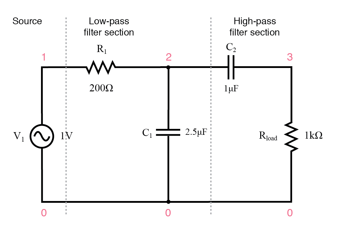
Capacitive band‑pass filter.
capacitive bandpass filter
v1 1 0 ac 1 sin
r1 1 2 200
c1 2 0 2.5u
c2 2 3 1u
rload 3 0 1k
.ac lin 20 100 500
.plot ac v(3)
.end
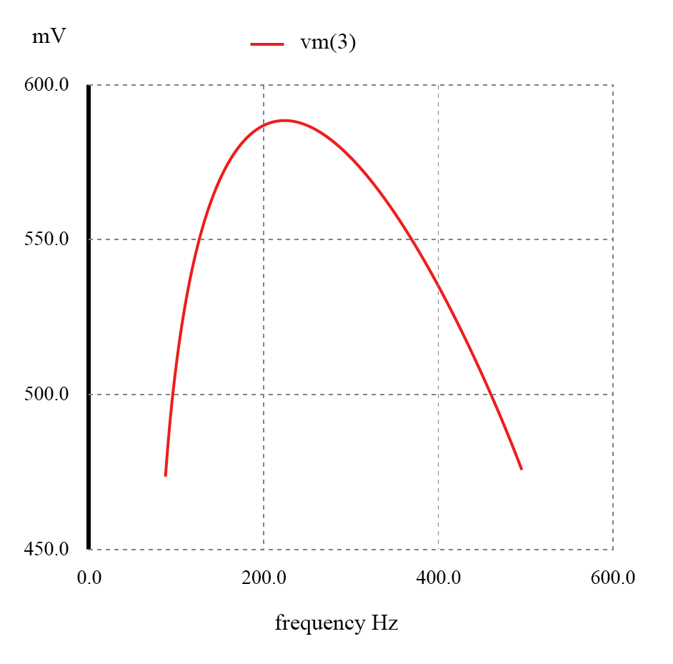
The response of a capacitive band‑pass filter peaks within a narrow frequency range.
Design a Band‑Pass Filter Using Inductors
While inductors can also realize a band‑pass response, capacitors typically provide higher “purity” in their reactive behavior, giving designers a clearer advantage. A representative inductor‑based design is shown here:
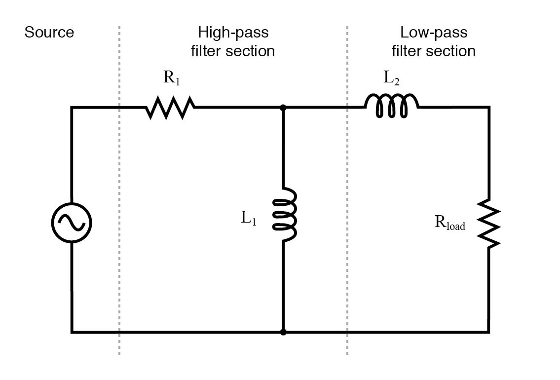
Inductive band‑pass filter.
Reordering the high‑pass and low‑pass sections does not alter the fundamental filtering action; the circuit still rejects frequencies outside the desired band.
However, relying solely on the blocking action of each stage introduces practical limitations. Even at the filter’s peak, the combined attenuation of the low‑pass and high‑pass sections can reduce the signal amplitude. In the SPICE analysis above, the load voltage never exceeds 0.59 V, despite a 1 V source. The attenuation worsens if the filter is made steeper or more selective.
More advanced techniques can achieve a flat‑topped pass‑band without sacrificing signal strength, and we will explore those methods later in this chapter.
REVIEW:
- A band‑pass filter allows only the frequencies within a specified range to pass, blocking both lower and higher frequencies.
- It can be built by cascading a low‑pass filter with a high‑pass filter (or vice versa).
- “Attenuate” means to reduce signal amplitude; it is the same principle behind lowering a stereo’s volume control.
RELATED WORKSHEETS:
- Active Filters Worksheet
Industrial Technology
- Understanding Filter Circuits: From Audio to Power Conditioning
- Low‑Pass Filters: Principles, Designs, and Practical Applications
- High‑Pass Filters: Design, Function, and Practical Applications
- Band‑Stop Filters: Design, Twin‑T Implementation, and Notch Frequency Analysis
- Resonant Filters: Designing Band‑Pass and Band‑Stop Circuits with LC Resonance
- Ceramic Filters for Molten Metal Casting: Design, Production, and Market Outlook
- Schaffner Launches Advanced FN 9262/9266 RFI Filters with IEC C14 PEMs for Medical & Consumer Applications
- Why Prefilling Fuel Filters Damages Equipment & How to Avoid It
- A Complete Guide to Filter Types in Signal Processing
- Key Factors in Choosing the Right Compressed Air Filter