


Resonant Filters: Designing Band‑Pass and Band‑Stop Circuits with LC Resonance
Up to this point, our filter designs have used either capacitors or inductors, but never both simultaneously. Combining L and C elements creates resonant behavior that can be harnessed to build precise band‑pass and band‑stop filters.
Series LC circuits exhibit minimal impedance at their resonant frequency, whereas parallel LC (tank) circuits exhibit maximum impedance at resonance. These two properties underpin the two fundamental strategies for constructing band‑pass and band‑stop filters.
For band‑pass filters, we either use a series LC to pass a signal or a parallel LC to short a signal. The following sections compare these two approaches and present SPICE simulations.
Series Resonant Band‑Pass Filter
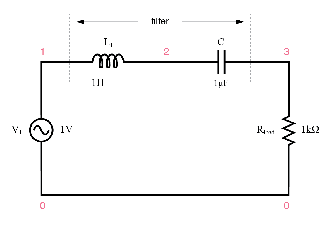
Series resonant LC band‑pass filter.
In this configuration, the series LC combination passes the desired frequency band while rejecting all others, ensuring virtually no attenuation within the pass band—a marked advantage over single‑component designs.
Because the resonant frequency is independent of circuit resistance, changing the load resistor does not shift the peak frequency. However, it does affect the slope of the Bode plot, thereby altering the filter’s selectivity.
series resonant bandpass filter
v1 1 0 ac 1 sin
l1 1 2 1
c1 2 3 1u
rload 3 0 1k
.ac lin 20 50 250
.plot ac v(3)
.end
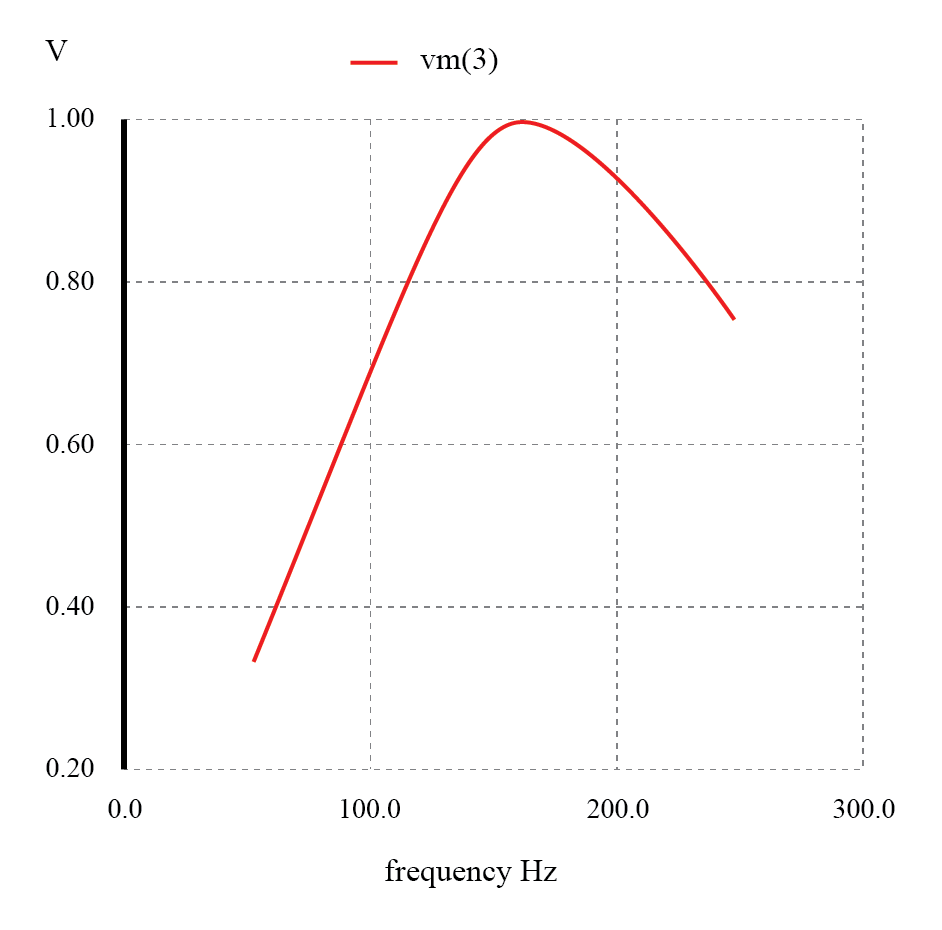
Series resonant band‑pass filter: voltage peaks at resonant frequency of 159.15 Hz.
For the parallel variant, a tank circuit shorts out signals outside the target band, allowing only the resonant frequency to reach the load.
Parallel Resonant Band‑Pass Filter
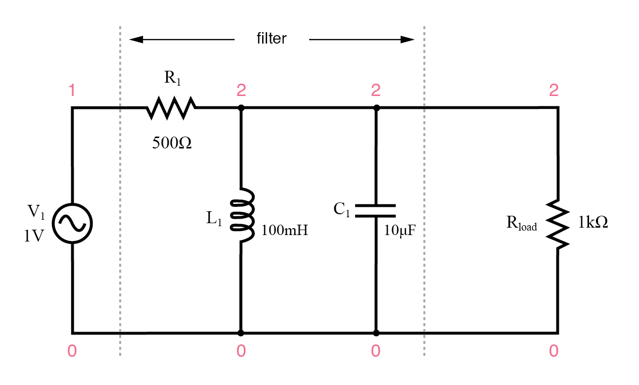
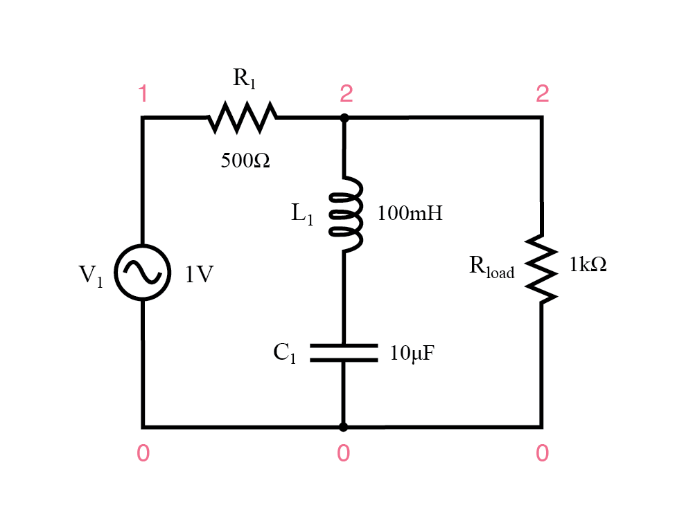
Parallel resonant band‑pass filter.
The tank’s high impedance at resonance lets the desired signal pass with minimal loss. Off‑resonance, its low impedance short‑circuits the signal, diverting most of it across the series resistor R1.
parallel resonant bandpass filter
v1 1 0 ac 1 sin
r1 1 2 500
l1 2 0 100m
c1 2 0 10u
rload 2 0 1k
.ac lin 20 50 250
.plot ac v(2)
.end
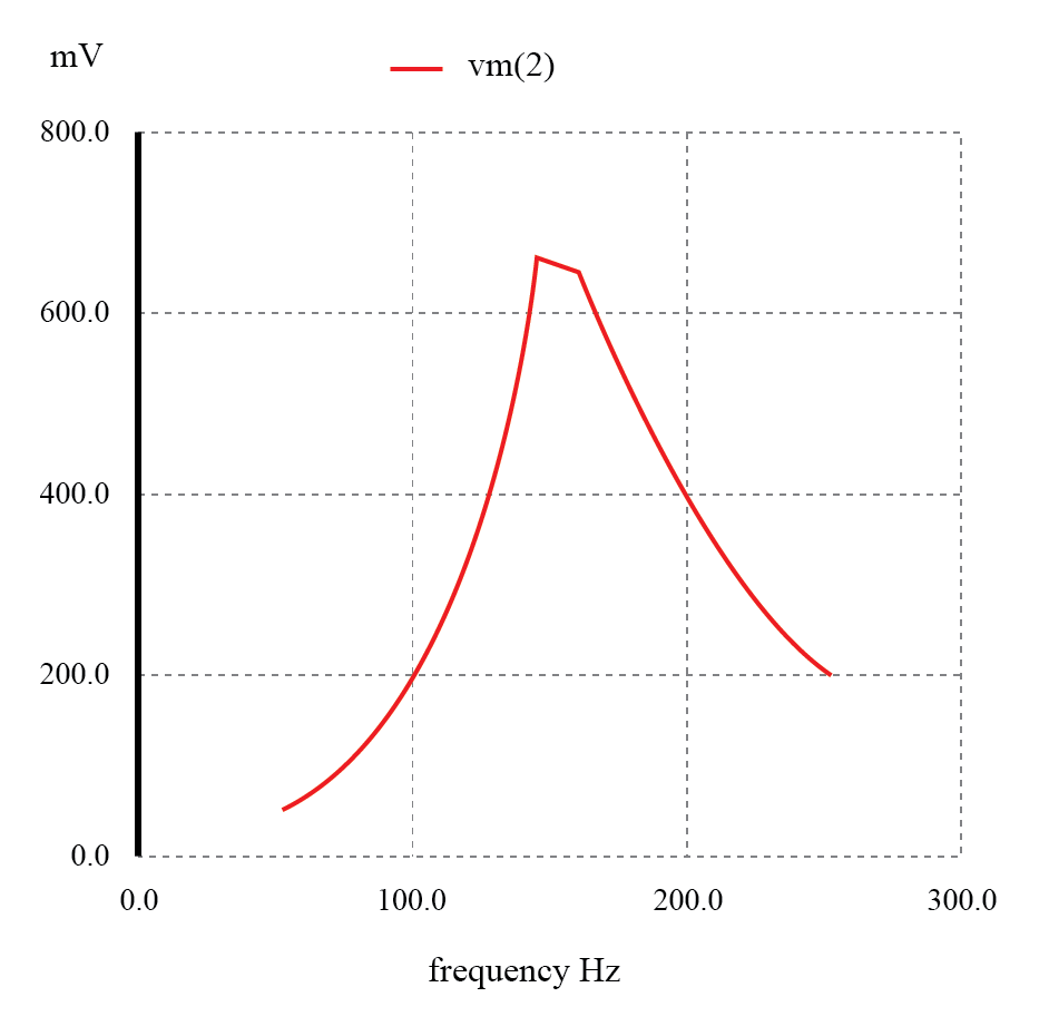
Parallel resonant filter: voltage peaks at resonant frequency of 159.15 Hz.
Both designs require a series resistor to limit current, meaning they cannot deliver the full source voltage to the load. Nonetheless, the parallel LC band‑pass is ubiquitous in analog radio tuners, where a variable capacitor in the tank selects a specific broadcast frequency.
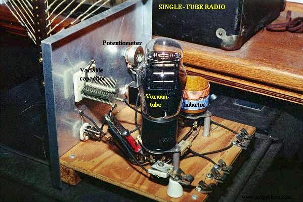
Variable capacitor tunes radio receiver tank circuit to select one out of many broadcast stations.
Similarly, LC resonances can be used to create band‑stop (notch) filters. The series LC short‑circuits at resonance, while the parallel LC presents high impedance, blocking the target frequency.
Series Resonant Band‑Stop Filter
Series resonant band‑stop filter.
At resonance, the series LC’s low impedance shorts the signal across R1, preventing it from reaching the load.
series resonant bandstop filter
v1 1 0 ac 1 sin
r1 1 2 500
l1 2 3 100m
c1 3 0 10u
rload 2 0 1k
.ac lin 20 70 230
.plot ac v(2)
.end
Series resonant band‑stop filter: Notch frequency = LC resonant frequency (159.15 Hz).
Parallel Resonant Band‑Stop Filter
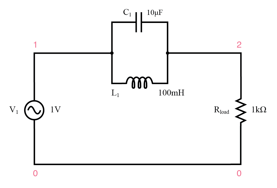
Parallel resonant band‑stop filter.
The parallel LC presents a high impedance at resonance, effectively blocking the target frequency while letting all others pass.
parallel resonant bandstop filter
v1 1 0 ac 1 sin
l1 1 2 100m
c1 1 2 10u
rload 2 0 1k
.ac lin 20 100 200
.plot ac v(2)
.end
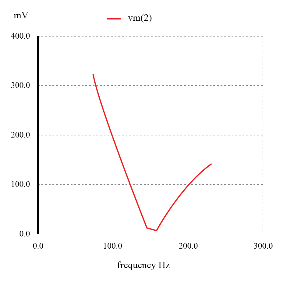
Parallel resonant band‑stop filter: Notch frequency = LC resonant frequency (159.15 Hz).
The absence of a series resistor in the parallel design yields minimal attenuation for desired signals, while the notch depth remains pronounced—a hallmark of high‑selectivity filtering.
Filter performance hinges on the purity of the inductors and capacitors. Any stray resistance—especially within the inductor—reduces selectivity and can introduce anti‑resonant behavior that shifts the peak or notch frequency.
Capacitive‑Inductive Low‑Pass Filter
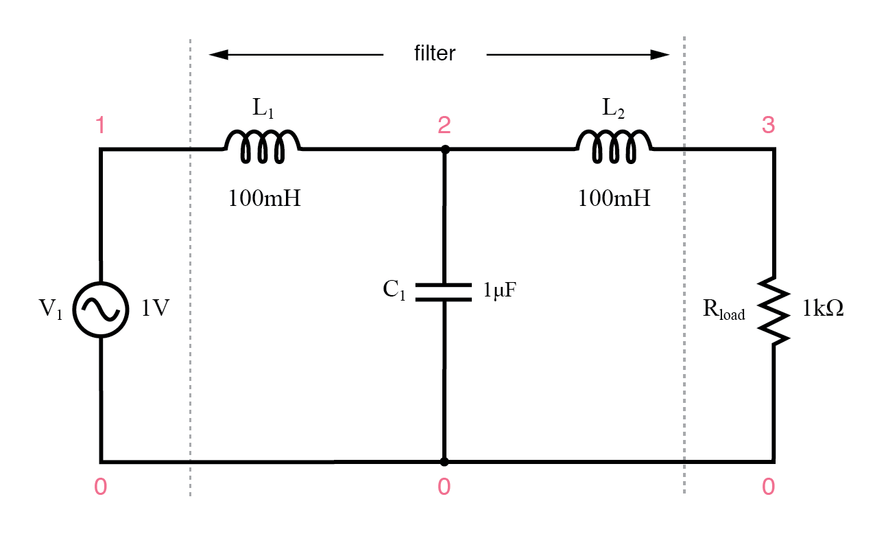
Capacitive Inductive low‑pass filter.
Inductors attenuate high frequencies while capacitors short them out, ostensibly allowing only low frequencies to reach the load. However, the LC pair inevitably introduces a resonant point that can dramatically alter the response.
SPICE analysis reveals a peak around 526 Hz, turning the intended low‑pass into a band‑pass. The output voltage at this frequency even exceeds the source voltage due to resonance between L1 and C2.
lc lowpass filter
v1 1 0 ac 1 sin
l1 1 2 100m
c1 2 0 1u
l2 2 3 100m
rload 3 0 1k
.ac lin 20 100 1k
.plot ac v(3)
.end
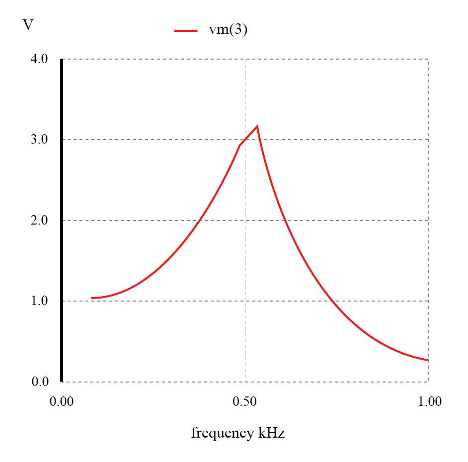
Unexpected response of L‑C low‑pass filter.
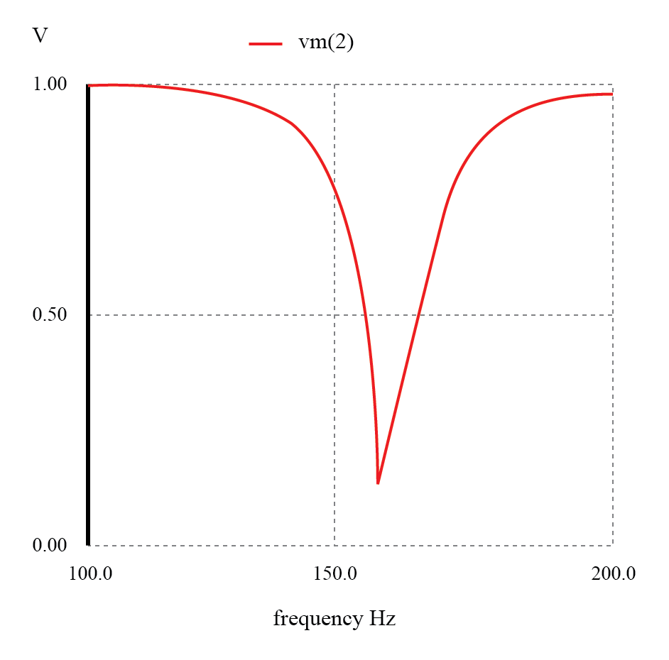
Examining the voltage across C1 (vm(2)) and the source current I(v1) shows simultaneous spikes at the resonant frequency, confirming the problematic resonance.
To achieve a flat response, the filter’s input and output impedances must match the source and load. The characteristic impedance is Z = √(L/C). For L = 100 mH and C = 1 µF, Z ≈ 316 Ω.
Impedance‑Matched Filter
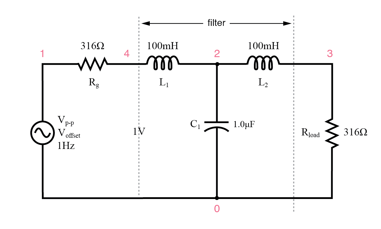
Circuit of source and load matched L‑C low‑pass filter.
LC matched lowpass filter
V1 1 0 ac 1 SIN
Rg 1 4 316
L1 4 2 100m
C1 2 0 1.0u
L2 2 3 100m
Rload 3 0 316
.ac lin 20 100 1k
.plot ac v(3)
.end
The matched configuration yields a nearly flat response up to the cut‑off frequency, dramatically improving load regulation compared to the unmatched design.
In AC/DC power supplies, LC low‑pass filters are often used as the final stage to suppress ripple. Despite potential resonances, the large component values shift the resonant frequency far below the ripple spectrum (e.g., 120 Hz for a 60 Hz mains supply), preventing interference.
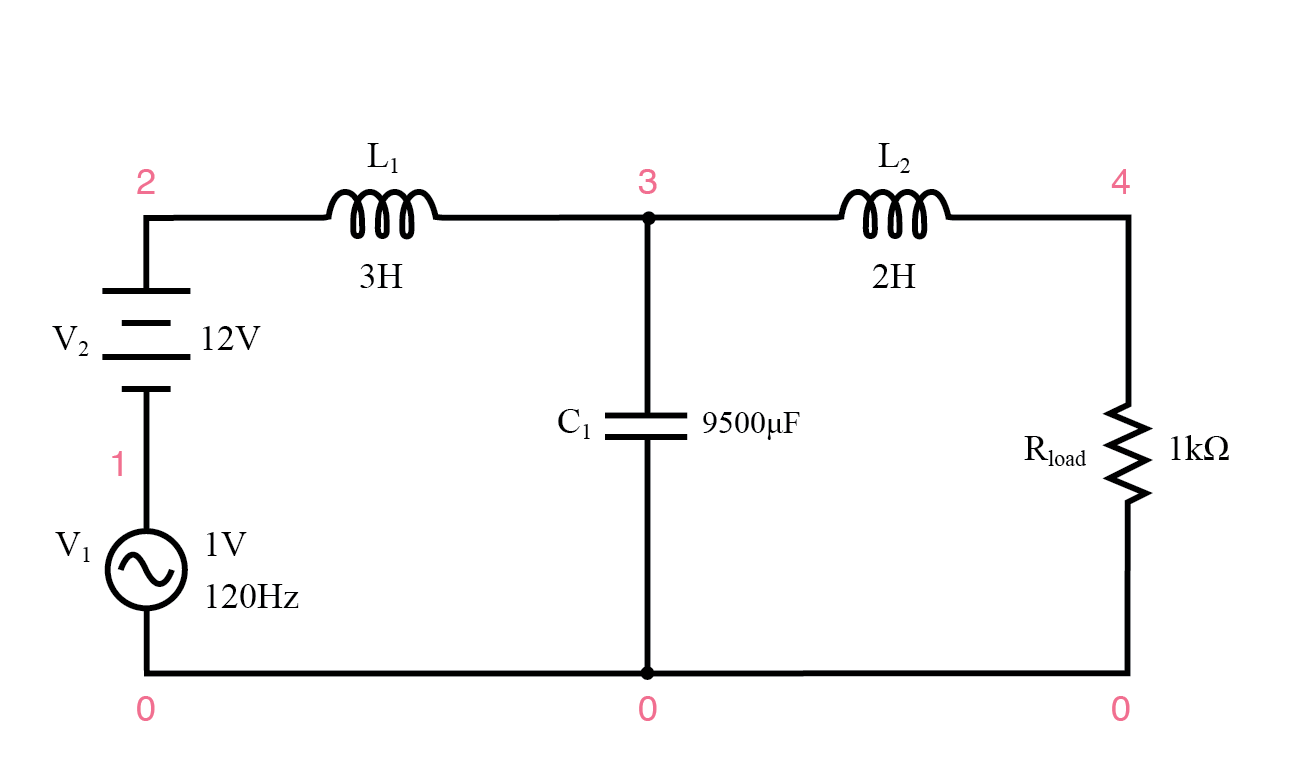
AC/DC power supply filter provides “ripple free” DC power.
AC/DC power supply filter provides “ripple free” DC power

ac/dc power supply filter
v1 1 0 ac 1 sin
v2 2 1 dc
l1 2 3 3
c1 3 0 9500u
l2 3 4 2
rload 4 0 1k
.dc v2 12 12 1
.ac lin 1 120 120
.print dc v(4)
.print ac v(4)
.end
v2 v(4)

1.200E+01 1.200E+01 DC voltage at load = 12 volts

freq v(4)
1.200E+02 3.412E-05 AC voltage at load = 34.12 microvolts
With 12 V DC at the load and only 34.12 µV of AC ripple, this design demonstrates the effectiveness of LC filtering in power supplies.
High‑pass filters using LC pairs also benefit from placing the resonant frequency well outside the target bands. Any signal near resonance will distort the filter’s behavior.
REVIEW:
- Resonant LC combinations enable highly selective band‑pass and band‑stop filters without the performance loss associated with additional resistive elements.
RELATED WORKSHEETS:
- Resonance Worksheet
- Passive Filter Circuits Worksheet
Industrial Technology
- Understanding Filter Circuits: From Audio to Power Conditioning
- Low‑Pass Filters: Principles, Designs, and Practical Applications
- High‑Pass Filters: Design, Function, and Practical Applications
- Band‑Pass Filters: Design, Implementation, and Practical Tips
- Band‑Stop Filters: Design, Twin‑T Implementation, and Notch Frequency Analysis
- Ceramic Filters for Molten Metal Casting: Design, Production, and Market Outlook
- Schaffner Launches Advanced FN 9262/9266 RFI Filters with IEC C14 PEMs for Medical & Consumer Applications
- Why Prefilling Fuel Filters Damages Equipment & How to Avoid It
- A Complete Guide to Filter Types in Signal Processing
- Key Factors in Choosing the Right Compressed Air Filter