


Choosing the Right Cable Size for Electrical Installations – Imperial & Metric Examples
How to Determine the Proper Size of Wire & Cable for Electrical Wiring Installation?
The following step by step guide will show you how to find the right size of cable and wire or any other conductor for electrical wiring installation with solved examples (in both British or English and SI System i.e. Imperial and Metric System respectively).
Keep in mind that it is very important to select proper wire size while sizing a wire for electrical installations. An inappropriate size of wire for bigger loads having high current may create chaos which leads to failure of the electrical equipment, hazardous fire and serious injuries.
Voltage Drop in Cables
We know that all conductors, wires and cables (except superconductors) have some amount of resistance.
This resistance is directly proportional to the length and inversely proportional to the diameter of conductor i.e.
R ∝ L/a … [Laws of resistance R = ρ (L/a)]
Whenever current flows through a conductor, a voltage drop occurs in that conductor. Generally, voltage drop may be neglected for small length of conductors but in case of a lower diameter and long length conductors, we have to take into account the considerable voltage drops for proper wiring installation and future load management.
According to IEEE rule B-23, at any point between power supply terminal and installation, Voltage drop should not increase above 2.5% of the provided (supply) voltage.
Related Posts:
- How to Find the Proper Size of Circuit Breaker? Breaker Calculator & Examples
- How to Find the Voltage & Ampere Rating of Switch, Plug, Outlet & Receptacle
- How to calculate the Cable size for LT & HT Motors?

Example:
If the supply voltage is 220V AC, then the value of allowable voltage drop should be;
- Allowable Voltage Drop = 220 x (2.5/100) = 5.5V
Similarly, if the supply voltage is 120V AC, the allowable voltage drop should be no more than 3V ( 120V x 2.5%).
In electrical wiring circuits, voltage drops also occur from the distribution board to the different sub circuit and final sub circuits, but for sub circuits and final sub circuits, the value of voltage drop should be half of that allowable voltage drops (i.e. 2.75V of 5.5V as calculated above)
Normally, Voltage drop in tables is described in Ampere per meter (A/m) e.g. what would be the voltage drop in a one meter cable which caries one Ampere current?
There are two methods to define the voltage drop in a cable which we will discus below.
In SI (System international and metric system) voltage drop is described by ampere per meter (A/m).
In FPS (foot pound system) voltage drop is described in length based which is 100 feet.
- Update: Now you may also use the following electrical Calculators to find Voltage drop & the wire size in American wire gauge systems.
- Electrical Wire & Cable Size Calculator (Copper & Aluminum)
- Wire & Cable Size Calculator in AWG
- Voltage Drop in Wire & Cable Calculator
Tables & Charts for Proper Cable & Wire Sizes
Below are the important tables which you should follow for determining the proper size of cable for Electrical Wiring Installation.
Click image to enlarge
Click image to enlarge
 Click image to enlarge
Click image to enlarge
 Click image to enlarge
How to Find the Voltage Drop in a Cable?
To find voltage drop in a cable, follow the simple steps given below.
- First of all, find the maximum allowable voltage drop.
- Now, find the load current.
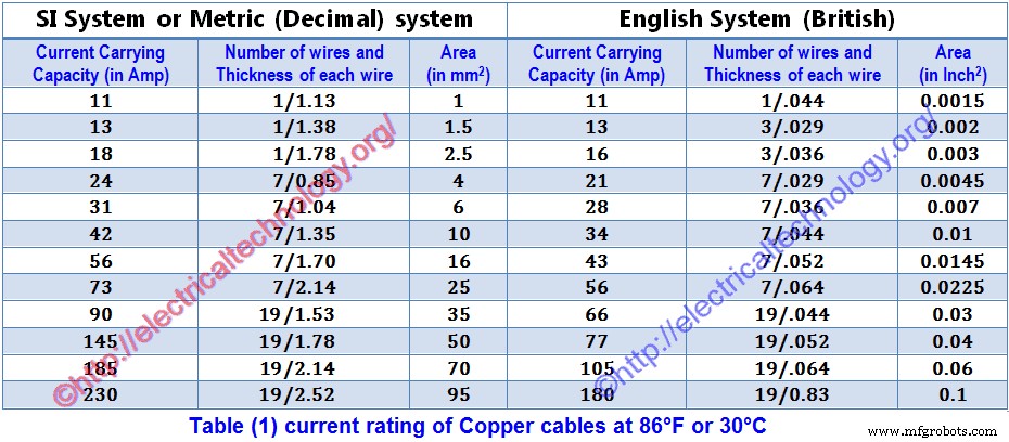
- Now, according to the load current, select a proper cable (which current rating should be nearest to the calculated load current) from table 1.
- From Table 1, find the voltage drop in meter or 100 feet (what system you prefer) according its rated current.
(Stay cool :) We will follow both methods and systems for finding voltage drops (in meters and 100 feet) in our solved example for whole electrical installation wiring).
- Now, calculate the voltage drop for the actual length of the wiring circuit according to its rated current with the help of following formulas.
(Actual length of circuit x volt drop for 1m) /100 ===> to find Volt drop in per meter.
(Actual length of circuit x volt drop for 100ft) /100 ===> to find volt drop in 100 feet.
- Now multiply this calculated value of volt drop by load factor where;
Load factor = Load Current to be taken by Cable/ Rated Current of Cable given in the table.
- This is the value of Volt drop in the cables when load current flows through it.
- If the calculated value of voltage drop is less than the value calculated in step (1) (Maximum allowable voltage drop), than the size of selected cable is proper
- If the calculated value of voltage drop is greater than the value calculated in step (1) (Maximum allowable voltage drop), than calculate voltage drop for the next (greater in size) cable and so on until the calculated value of voltage drop became less than the maximum allowable voltage drop calculated in step (1).
How to Determine the Proper Cable & Wire Size for Given Load?
Below are solved examples showing how to find the proper Cable Size for Given Load.
For a given load, cable size may be found with the help of different tables but we should keep in mind and follow the rules about voltage drop.
Determining the size of cable for a given load, take into account the following rules.
For a given load except the known value of current, there should be 20% extra scope of current for additional, future or emergency needs.
From Energy meter to Distribution board, Voltage drop should be 1.25% and for final sub circuit, voltage drop should not exceed 2.5% of Supply voltage.
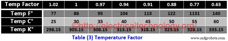
Consider the change in temperature, when needed, use temperature factor (Table 3)
Also, consider the load factor when finding the size of cable
When determining the cable size, consider the wiring system i.e. in an open wiring system, temperature would be low but in conduit wiring, temperature increases due to the absence of air.
- Note: Keep in mind Diversity Factor in Electrical Wring Installation while selecting the proper size of cable for electrical wiring installation
Solved Examples of Proper Wire & Cable Size
Following are the examples of determining the proper Size of cables for electrical wiring installation which will make it easy to understand the method of “how to determine the proper size of cable for a given load”.
Example 1 … (Imperial, British or English System)
For Electrical wiring installation in a building, Total load is 4.5kW and total length of cable from energy meter to sub circuit distribution board is 35 feet. Supply voltages are 220V and temperature is 40°C (104°F). Find the most suitable size of cable from energy meter to sub circuit if wiring is installed in conduits.
Solution:-
- Total Load = 4.5kW = 4.5 x1000W = 4500W
- 20% additional load = 4500 x (20/100) = 900W
- Total Load = 4500W + 900W = 5400W
- Total Current = I = P/V = 5400W /220V =24.5A
Now select the size of cable for load current of 24.5A (from Table 1) which is 7/0.036 (28 Amperes). It means we can use 7/0.036 cable according to table 1.
Now check the selected (7/0.036) cable with temperature factor in Table 3, so the temperature factor is 0.94 (in table 3) at 40°C (104°F) and current carrying capacity of (7/0.036) is 28A, therefore, current carrying capacity of this cable at 40°C (104°F) would be;
Current rating for 40°C (104°F) = 28 x 0.94 = 26.32 Amp.
Since the calculated value (26.32 Amp) at 40°C (104°F) is less than that of current carrying capacity of (7/0.036) cable which is 28A, therefore this size of cable (7/0.036) is also suitable with respect to temperature.
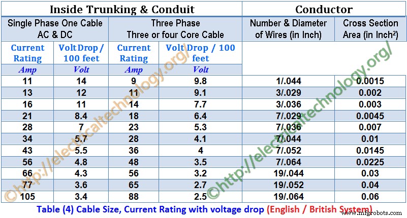
Now find the voltage drop for 100 feet for this (7/0.036) cable from Table 4 which is 7V, But in our case, the length of cable is 35 feet. Therefore, the voltage drop for 35 feet cable would be;
Actual Voltage drop for 35 feet = (7 x 35/100) x (24.5/28) = 2.1V
And Allowable voltage drop = (2.5 x 220)/100 = 5.5V
Here The Actual Voltage Drop (2.1V) is less than that of maximum allowable voltage drop of 5.5V. Therefore, the appropriate and most suitable cable size is (7/0.036) for that given load for Electrical Wiring Installation.
- Related Post: How to Wire Auto & Manual Changeover & Transfer Switch? (1 & 3 Phase)
Example 2 … (SI / Metric / Decimal System)
What type and size of cable suits for given situation
- Load = 5.8kW
- Volts = 230V AV
- Length of Circuit = 35 meter
- Temperature = 35°C (95°F)
Solution:-
Load = 5.8kW = 5800W
Voltage = 230V
Current = I = P/V = 5800 / 230 = 25.2A
20% additional load current = (20/100) x 5.2A = 5A
Total Load Current = 25.2A + 5A = 30.2A
Now select the size of cable for load current of 30.2A (from Table 1) which is 7/1.04 (31 Amperes). It means we can use 7/0.036 cable according to the table 1.
Now check the selected (7/1.04) cable with temperature factor in Table 3, so the temperature factor is 0.97 (in table 3) at 35°C (95°F) and current carrying capacity of (7/1.04) is 31A, therefore, current carrying capacity of this cable at 40°C (104°F) would be;
Current rating for 35°C (95°F) = 31 x 0.97 = 30 Amp.
Since the calculated value (30 Amp) at 35°C (95°F) is less than that of current carrying capacity of (7/1.04) cable which is 31A, therefore this size of cable (7/1.04) is also suitable with respect to temperature.
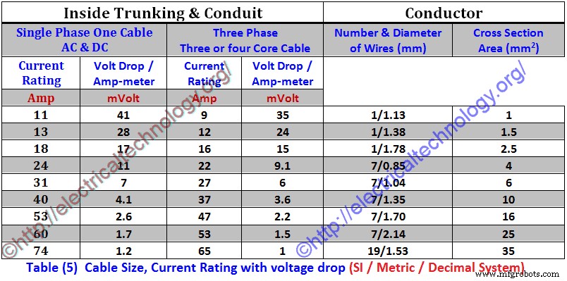
Now find the voltage drop for per ampere meter for this (7/1.04) cable from (Table 5) which is 7mV, But in our case, the length of cable is 35 meter. Therefore, the voltage drop for 35 meter cable would be:
Actual Voltage drop for 35meter =
= mV x I x L
= (7/1000) x 30×35 = 7.6V
And Allowable voltage drop = (2.5 x 230)/100 = 5.75V
Here the actual Voltage drop (7.35V) is greater than that of maximum allowable voltage drop of 5.75V. Therefore, this is not a suitable size of cable for that given load. So we will select the next size of selected cable (7/1.04) which is 7/1.35 and find the voltage drop again.
According to Table (5) the current rating of 7/1.35 is 40 Amperes and the voltage drop in per ampere meter is 4.1 mV (See table (5)). Therefore, the actual voltage drop for 35 meter cable would be;
Actual Voltage drop for 35 meter =
= mV x I x L
(4.1/1000) x 40×35 = 7.35V = 5.74V
This drop is less than that of maximum allowable voltage drop. So this is the most appropriate and suitable cable or wire size.
Example 3
Following Loads are connected in a building:-
Sub-Circuit 1
- 2 lamps each o 1000W and
- 4 fans each of 80W
- 2 TV each of 120W
Sub-Circuit 2
- 6 Lamps each of 80W and
- 5 sockets each of 100W
- 4 lamps each of 800W
If supply voltages are 230 V AC, then calculate circuit current and Cable size for each Sub-Circuit?
Solution:-
Total load of Sub-Circuit 1
= (2 x 1000) + (4 x 80) + (2×120)
= 2000W + 320W + 240W = 2560W
Current for Sub-Circuit 1 = I = P/V = 2560/230 = 11.1A
Total load of Sub-Circuit 2
= (6 x 80) + (5 x 100) + (4 x 800)
= 480W + 500W + 3200W= 4180W
Current for Sub-Circuit 2 = I = P/V = 4180/230 = 18.1A
Therefore, Cable suggested for sub circuit 1 = 3/.029” (13 Amp) or 1/1.38 mm (13 Amp)
Cable suggested for Sub-Circuit 2 = 7/.029” (21 Amp) or 7/0.85 mm (24 Amp)
Total Current drawn by both Sub-Circuits = 11.1A + 18.1A = 29.27 A
So cable suggested for Main-Circuit = 7/.044″ (34 Amp) or 7/1.04 mm (31 Amp)
Example 4
A 10H.P (7.46kW) three phase squirrel cage induction motor of continuous rating using Star-Delta starting is connected through 400V supply by three single core PVC cables run in conduit from 250feet (76.2m) away from multi-way distribution fuse board. Its full load current is 19A. Average summer temperature in Electrical installation wiring is 35°C (95°F). Calculate the size of the cable for the motor?
Solution:-
- Motor load = 10H.P = 10 x 746 = 7460W *(1H.P = 746W)
- Supply Voltage = 400V (3-Phase)
- Length of cable = 250feet (76.2m)
- Motor full load Current = 19A
- Temperature factor for 35°C (95°F) = 0.97 (From Table 3)
Now select the size of cable for full load motor current of 19A (from Table 4) which is 7/0.36” (23 Amperes) *(Remember that this is a 3-phase system i.e. 3-core cable) and the voltage drop is 5.3V for 100 Feet. It means we can use 7/0.036 cable according Table (4).
Now check the selected (7/0.036) cable with temperature factor in table (3), so the temperature factor is 0.97 (in table 3) at 35°C (95°F) and current carrying capacity of (7/0.036”) is 23 Amperes, therefore, current carrying capacity of this cable at 40°C (104°F) would be:
Current rating for 40°C (104°F) = 23 x 0.97 = 22.31 Amp.
Since the calculated value (22.31 Amp) at 35°C (95°F) is less than that of current carrying capacity of (7/0.036) cable which is 23A, therefore this size of cable (7/0.036) is also suitable with respect to temperature.
Load factor = 19/23 = 0.826
Now find the voltage drop for 100feet for this (7/0.036) cable from table (4) which is 5.3V, But in our case, the length of cable is 250 feet. Therefore, the voltage drop for 250 feet cable would be;
Actual Voltage drop for 250feet = (5.3 x 250/100) x 0.826 = 10.94V
And maximum Allowable voltage drop = (2.5/100) x 400V= 10V
Here the actual Voltage drop (10.94V) is greater than that of maximum allowable voltage drop of 10V. Therefore, this is a not a suitable size of cable for the given load. So we will select the next size of selected cable (7/0.036) which is 7/0.044 and find the voltage drop again. According to Table (4) the current rating of 7/0.044 is 28 Amperes and the volt drop in per 100 feet is 4.1V (see Table 4). Therefore, the actual voltage drop for 250 feet cable would be;
Actual Voltage drop for 250 feet =
= Volt drop per 100 feet x length of cable x load factor
= (4.1/100) x 250 x 0.826 = 8.46V
And Maximum Allowable voltage drop = (2.5/100) x 400V= 10V
The actual voltage drop is less than that of maximum allowable voltage drop. So this is the most appropriate and suitable cable size for electrical wiring installation in a given situation.
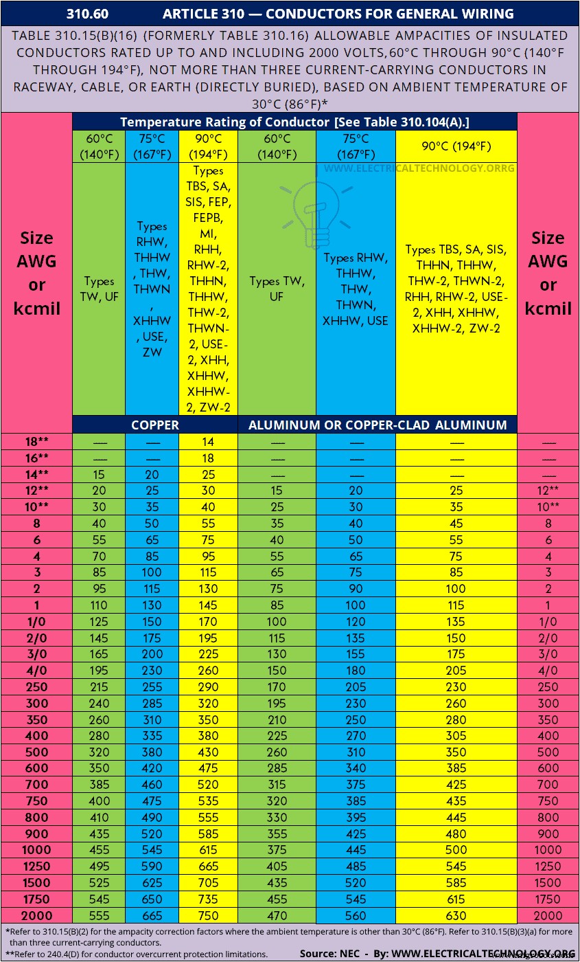
NEC Wire Size Table 310.15(B)(16) (formerly Table 310.16) & Chart
NEC (National Electrical Code) Table 310.15(B)(16) (formerly Table 310.16) – 310.60 – ARTICLE 310 – Conductors for General Wiring & Allowable Ampacities of Conductors & Wire Sizes based on AWG (American Wire Gauge).
| 310.60 ARTICLE 310 — CONDUCTORS FOR GENERAL WIRING | |||||||
| Table 310.15(B)(16) (formerly Table 310.16) Allowable Ampacities of Insulated Conductors Rated Up to and Including 2000 Volts, 60°C Through 90°C (140°F Through 194°F), Not More Than Three Current-Carrying Conductors in Raceway, Cable, or Earth (Directly Buried), Based on Ambient Temperature of 30°C (86°F)* | |||||||
| Size AWG or kcmil | Temperature Rating of Conductor [See Table 310.104(A).] | Size AWG or kcmil | |||||
| 60°C (140°F) | 75°C (167°F) | 90°C (194°F) | 60°C (140°F) | 75°C (167°F) | 90°C (194°F) | ||
| Types TW, UF | Types RHW, THHW, THW, THWN, XHHW, USE, ZW | Types TBS, SA, SIS, FEP, FEPB, MI, RHH, RHW-2, THHN, THHW,
THW-2, THWN-2, USE-2, XHH, XHHW, XHHW-2, ZW-2 |
Types TW, UF | Types RHW, THHW, THW, THWN, XHHW, USE | Types TBS, SA, SIS, THHN, THHW,
THW-2, THWN-2, RHH, RHW-2, USE-2, XHH, XHHW, XHHW-2, ZW-2 |
||
| COPPER | ALUMINUM OR COPPER-CLAD ALUMINUM | ||||||
| 18** | — | — | 14 | — | — | — | — |
| 16** | — | — | 18 | — | — | — | — |
| 14** | 15 | 20 | 25 | — | — | — | — |
| 12** | 20 | 25 | 30 | 15 | 20 | 25 | 12** |
| 10** | 30 | 35 | 40 | 25 | 30 | 35 | 10** |
| 8 | 40 | 50 | 55 | 35 | 40 | 45 | 8 |
| 6 | 55 | 65 | 75 | 40 | 50 | 55 | 6 |
| 4 | 70 | 85 | 95 | 55 | 65 | 75 | 4 |
| 3 | 85 | 100 | 115 | 65 | 75 | 85 | 3 |
| 2 | 95 | 115 | 130 | 75 | 90 | 100 | 2 |
| 1 | 110 | 130 | 145 | 85 | 100 | 115 | 1 |
| 1/0 | 125 | 150 | 170 | 100 | 120 | 135 | 1/0 |
| 2/0 | 145 | 175 | 195 | 115 | 135 | 150 | 2/0 |
| 3/0 | 165 | 200 | 225 | 130 | 155 | 175 | 3/0 |
| 4/0 | 195 | 230 | 260 | 150 | 180 | 205 | 4/0 |
| 250 | 215 | 255 | 290 | 170 | 205 | 230 | 250 |
| 300 | 240 | 285 | 320 | 195 | 230 | 260 | 300 |
| 350 | 260 | 310 | 350 | 210 | 250 | 280 | 350 |
| 400 | 280 | 335 | 380 | 225 | 270 | 305 | 400 |
| 500 | 320 | 380 | 430 | 260 | 310 | 350 | 500 |
| 600 | 350 | 420 | 475 | 285 | 340 | 385 | 600 |
| 700 | 385 | 460 | 520 | 315 | 375 | 425 | 700 |
| 750 | 400 | 475 | 535 | 320 | 385 | 435 | 750 |
| 800 | 410 | 490 | 555 | 330 | 395 | 445 | 800 |
| 900 | 435 | 520 | 585 | 355 | 425 | 480 | 900 |
| 1000 | 455 | 545 | 615 | 375 | 445 | 500 | 1000 |
| 1250 | 495 | 590 | 665 | 405 | 485 | 545 | 1250 |
| 1500 | 525 | 625 | 705 | 435 | 520 | 585 | 1500 |
| 1750 | 545 | 650 | 735 | 455 | 545 | 615 | 1750 |
| 2000 | 555 | 665 | 750 | 470 | 560 | 630 | 2000 |
|
|||||||
Here is the NEC table as a chart (image format to downloads as a reference)
Related Posts:
- How to Size a Load Center, Panelboards and Distribution Board?
- How to Determine the Number of Circuit Breakers in a Panel Board?
- How to Determine the Right Size Capacity of a Subpanel?
- How to Calculate the Suitable Capacitor Size in Farads & kVAR for Power factor Improvement
- How to Convert Capacitor Farads into kVAR & Vice Versa (For Power factor improvement)
- How To check a Capacitor with Digital & Analog Multimeter. 8 Methods
- How to Check the Value of Burnt Resistor. 3 Handy methods
- How To: Electrical & Electronics Tutorials
- Basic Electrical Wiring Installation Tutorials
Industrial Technology
- Master Cable Duct Installation in Electrical Panels Using E3.series
- Comprehensive Electrical Wiring Installation Guides & Diagrams
- Accurate Guide to Calculating Capacitor Bank Size (µF & kVAR) for Power Factor Improvement
- How to Determine the Proper Size of Earth Conductors, Earthing Leads, and Earth Electrodes
- Calculate the Correct Circuit Breaker Size: A Practical Guide & Online Calculator
- Step‑by‑Step Guide: Wiring Solar Panels & Batteries in Parallel for a Reliable 12V System
- Step-by-Step Guide: Wiring Solar Panels & Batteries in Series for a Reliable 24V System
- Choosing the Right Inverter Size for Your Home Appliances: A Practical Guide
- Choosing the Right Inventory System for Your Warehouse: A Practical Guide
- Choosing the Ideal Contract Manufacturer for Your Business Success