


Build an Arduino Joystick Module: A Step-by-Step Guide
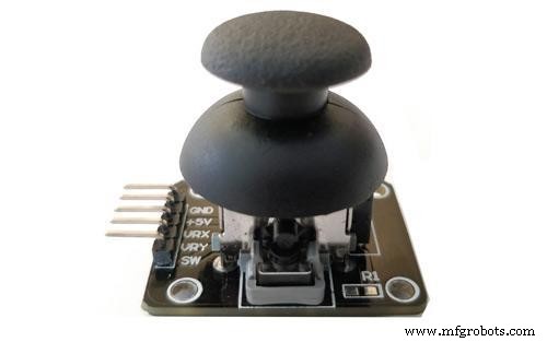
Joystick Module
Are you currently handling projects related to motion and robotics? Then, there’s a chance that you’ve probably heard about the Arduino Joystick module, but you don’t know how to make one.
Or perhaps you want to get more information about how an Arduino joystick module works?
Then, you’re in the right place.
The goal of an Arduino Joystick is to communicate motion to an Arduino. And it does this in 2-D (2-axis), making it suitable for motion and robotics applications.
So, in this article, you’ll learn everything about the Arduino joystick module, how it works, and how to make an easy Arduino joystick circuit.
Are you ready? Let’s jump in!
What is a Joystick Module?
There’s hardly any robotic project that doesn’t require a joystick. It’s sometimes difficult to get a controller that would work for your projects, and it might even be expensive. But, a joystick module provides a more affordable way to achieve that same result.
Also, the joystick module works similarly to the joysticks found in analog gamepads. Its key components are two potentiometers tilted at 90-degree angles. Furthermore, there’s a connection between a short stick (with springs at the center) and the potentiometers.
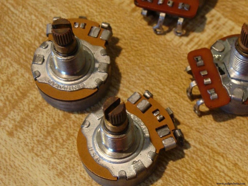
Potentiometers
The joystick module can output around 2.5V from the X and Y axis when it’s resting. Now, when you move the Joystick, the output will vary from 0V to 5V. However, this depends on the direction.
Plus, if you use a microcontroller with the joystick module, the real value in the resting position would be around 512. Thus, when you move this Joystick, you can see the values change from 0 to 1023, but this depends on its position.
Pin Configuration
Here is the pin configuration for the joystick module:
| Pin No. | Pin Name | Description |
| 1 | GND | The module’s ground terminal |
| 2 | +5V | The module’s positive supply terminal |
| 3 | VRx | The voltage proportional to the X-axis |
| 4 | VRy | The voltage proportional to the Y-axis |
| 5 | SW | The switch of the module |
Features
Here are the key features of the Arduino joystick module:
- It has two independent potentiometers for each axis ( X and Y)
- It doesn’t have a lot of weight
- You can easily interface the module with most microcontrollers or Arduino
- It automatically returns to the center position when not in use
- It also has a cup-type knob
Technical Specifications
The specifications of the joystick module include:
- It has a 5V operating voltage
- The value of the internal potentiometer is 10k
- Its operating temperature is about 0 to 70 degrees Celsius
- The leads of the pin interface are 2.54mm
- The dimensions of the joystick module are: 1.57 in x 1.02 in x 1.26 in (4.0 cm x 2.6 cm x 3.2 cm)
- It has five pins
- Two potentiometers control the horizontal directions and vertical directions of the module.
Schematic Diagram
The image below shows the complete schematics of the joystick module. As we previously mentioned, the module features two potentiometers that control the X and Y-axis.
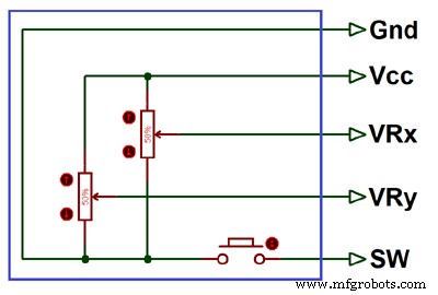
Schematics for Joystick Module
Plus, both potentiometers (10k) move independently. In other words, you can move them individually and in their directions. Also, there’s an internal connection of the switch (SW) pin to the push button.
Interfacing Joystick with Arduino
Joystick modules are compatible with many microcontrollers like Raspberry Pi, Arduino, and others. Plus, it’s easy to interface, and you first have to connect the VRx and VRy axis pins to the microcontroller’s ADC pins.
Also, if you plan on using a switch, then you should connect the button to the microcontroller’s digital pins.
Check out the diagram below to understand how to connect the joystick module to any microcontroller.
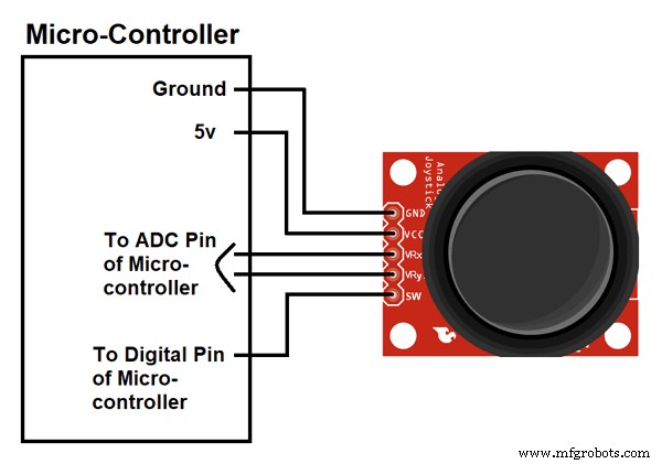
Joystick Module to Microcontroller
Now, the following diagram will show you how to interface a joystick module with an Arduino. With this diagram, you’ll be able to connect the module to the Arduino. Also, you’ll get an output depending on the direction you move the joystick knob.
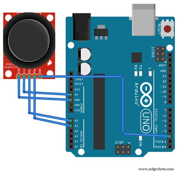
Joystick Module to Arduino
Once you’re done interfacing, we’ll find that each direction has a fixed output range. The following image will show you the output for the X and Y-axis depending on the movement of the joystick module in the four directions, +X, -X, +Y, and –Y. There’ll also be some analog values when you diagonally move the knob.
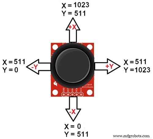
Movement Directions
If you want to know when you press your Joystick knob down, you can also connect the SW pin to digital pin 8 of the Arduino.
Additionally, the Joystick requires power to work correctly. So, connect the VCC pin to the Arduino’s 5V terminal and the GND to the Arduino’s GND terminal.
Arduino Code
It’s pretty easy to code this program on Arduino IDE. So, to get the best results, you’ll be measuring the motion of the Joystick from one digital input pin and two analog inputs. Then, the Arduino will display the impact on your monitor.
Here’s the best part
You don’t need a library to code this program. It simply reads the analog input and displays the values it gets from it. Plus, it also shows the output from the button push.
Here’s the raw sketch of the code:
- #define joyX A0
- #define joyY A1
- void setup() {
- Serial.begin(9600);
- }
- void loop() {
- // put your main code here, to run repeatedly:
- xValue = analogRead(joyX);
- yValue = analogRead(joyY);
- //print the values with to plot or view
- Serial.print(xValue);
- Serial.print(”\t”);
- Serial.println(yValue);
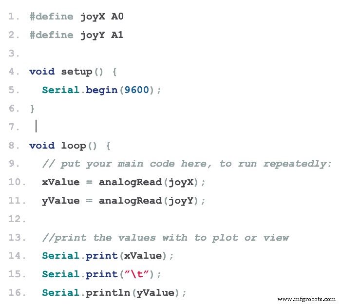
Image showing the Arduino code
Mapping
Sometimes, it’s not all about reading analog values, and there might be a need to map your module to a display or other interfaces. So, to help you with that, we’ll show you how to map the values of the above code to an 8×8 led matrix.
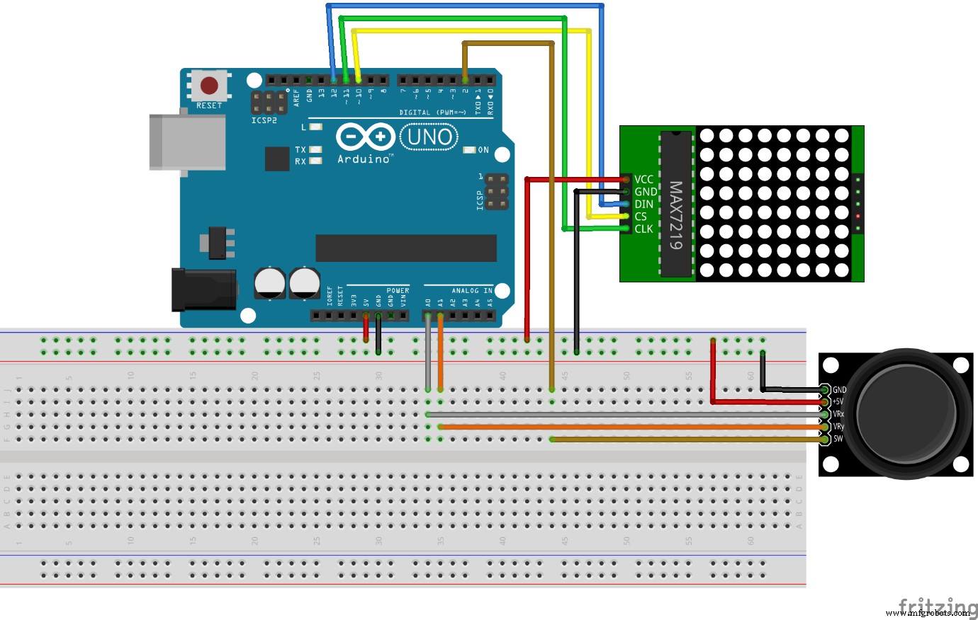
Arduino Mapping
The result of this process is to move the pixels on display with the Joystick. Also, it’s easy to change the code to map it to an OLED or graphic display.
- #include “LedControl.h”
- #define joyX A0
- #define joyY A1
- int xMap, yMap, xValue, yValue;
- LedControl lc=LedControl(12,11,10,1);
- void setup() {
- Serial.begin(115200);
- lc.shutdown(0,false);
- /* Set the brightness to a medium values */
- lc.setIntensity(0,8);
- /* and clear the display */
- lc.clearDisplay(0);
- }
- void loop() {
- // put your main code here, to run repeatedly:
- xValue = analogRead(joyX);
- yValue = analogRead(joyY);
- xMap = map(xValue, 0,1023, 0, 7);
- yMap = map(yValue,0,1023,7,0);
- lc.setLed(0,xMap,yMap,true);
- lc.clearDisplay(0);
- }
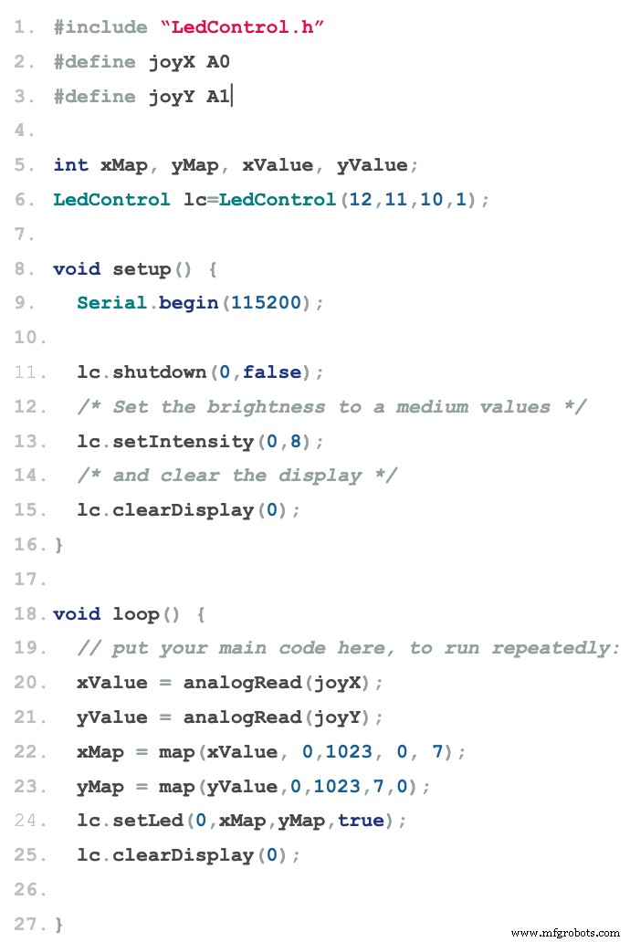
Image of code required to map the Arduino to an OLED or graphic display
Note: the above code shows that you can use the map() function to map the ranges to fit your preferences.
So, if you get everything right, the output on your serial monitor should look like this:
Applications
Here are some applications of the Arduino Joystick module:
- You can use the joystick module in robotics
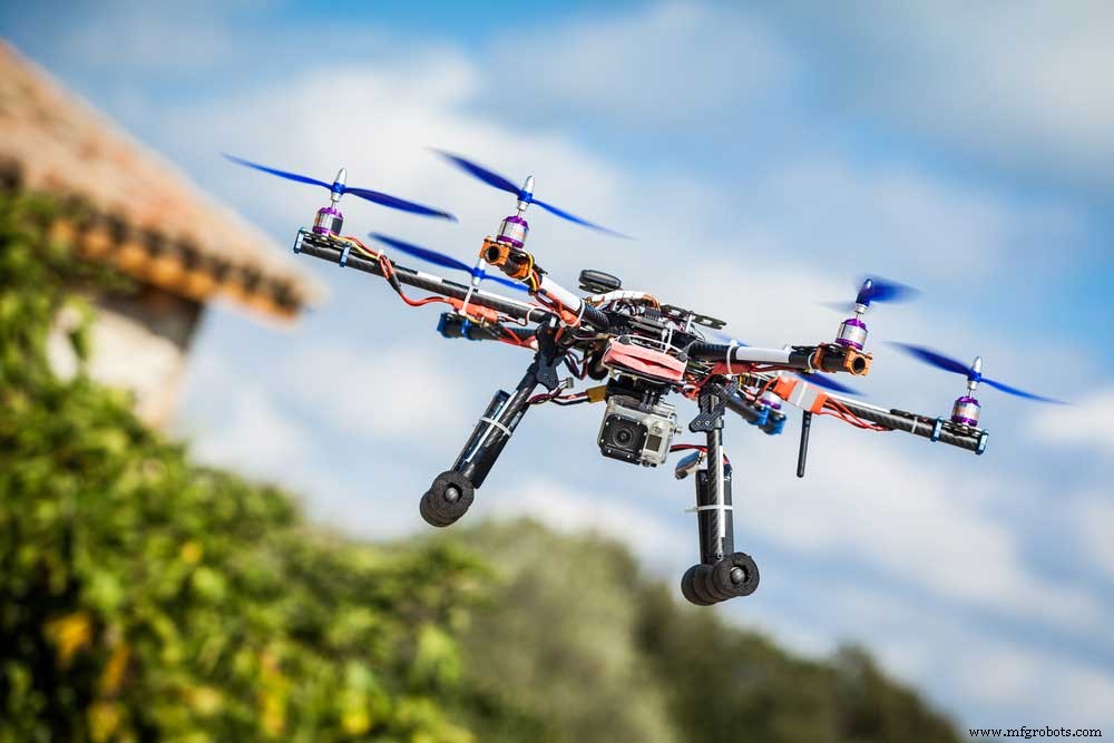
Robot Drone
- You can also control the movement of a movable camera
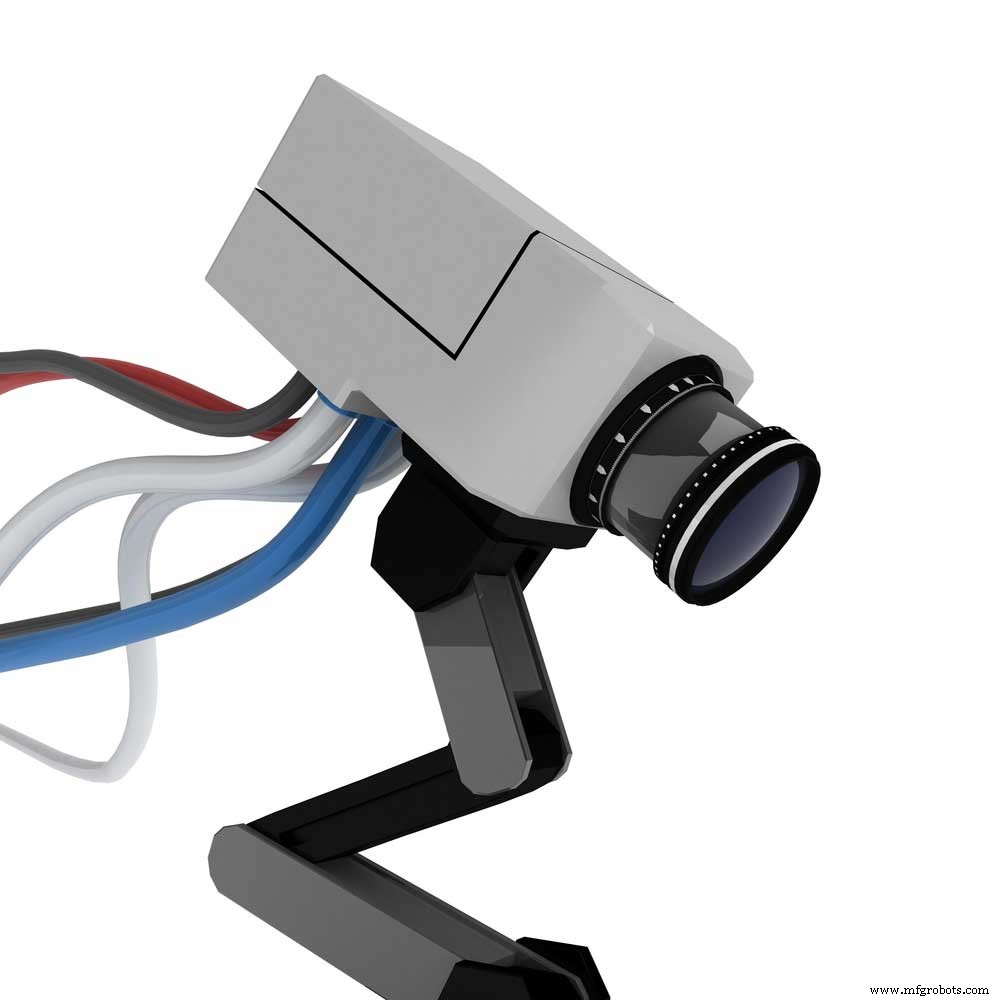
Movable Camera
- A wide variety of motion applications
Rounding Up
When you hear the word Joystick, the first thing that might come to mind would be game controllers. However, there are so many exciting applications of the joystick module when it comes to DIY electronics.

Game Controllers
Plus, these modules primarily work for DIY projects based On Arduino and robot control. As we earlier discussed, the joystick module first released analog output to feed the analog input depending on the horizontal or vertical movement of the stick.
Well, that rounds up this article. If you have any questions or suggestions, feel free to contact us. We’re always happy to help.
Industrial Technology
- Create a Custom Punchable Keyboard Button with Arduino: A Step-by-Step Guide
- Build a Custom Arduino Joystick Steering Wheel for Gaming
- Create Musical Tones with Arduino: A Step‑by‑Step Guide
- DIY Guide: Build Your Own DC Motor Controller
- Build an Arduino Proximity Sensor: Step‑by‑Step Guide with Components
- Build a Reliable DIY RFID Reader: Step-by-Step Guide
- Tachometer Circuit Explained: Function, Design, and Build Guide
- Build Your Own LED Driver: Benefits, Safety Tips, and Step‑by‑Step Guide
- Digital TV Antennas Demystified: Types, Easy Installation, and DIY Construction
- Build a Simple Arduino Speaker – Step‑by‑Step Guide