


Master the ADS1115: Features, Pinouts, and Arduino Integration Guide
Are you working with automotive electronics, high-precision instrumentation, or other high-precision collections? Or do you need a reliable device that can change analog to digital for data analysis, amplify, and enhance accuracy? Then, what you need is the ADS1115.
This article will give you a great head start if you’re new to this low-power device.
You’ll learn more about what it is, the pin configuration, working principle, how to interface it, and more.
Let’s begin!
What is ADS115 ADC Module?
The ADS115 ADC module is a small device with low power and a 16-bit precision AD converter. In other words, the device is an analog to digital converter that has a reference voltage internally. So, you can use these modules to strengthen, increase accuracy, and perform data analysis by converting analog to digital.
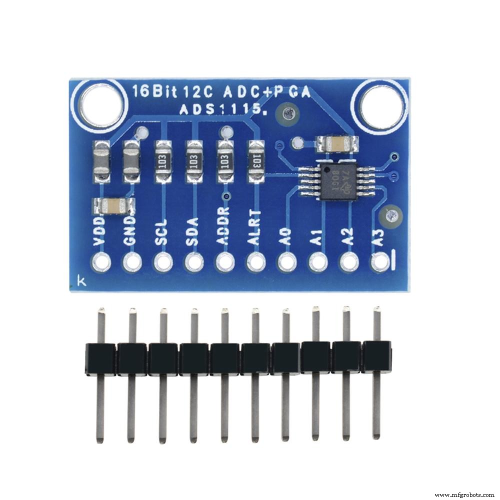
ADS1115 module
Source: Wikimedia Commons
How Does the ADS115 Module Work?
Typically, this module features an oscillator and onboard reference. So, it transfers data via a compatible serial interface (I2C). While at it, the device selects four IC2 slave addresses. Also, it utilizes one working power that ranges from 2.0 volts to 5.5 volts.
The ADS 115 executes a conversion rate of about 860 SPS (samples per second). Also, the device comes with an onboard PGA (programmable gain amplifier). The onboard PGA offers a range input of ±256mV from the PSV (power supply voltage). As a result, the PSV measures large and small high-resolution signals.
Further, the AD1115 features an input MUX (multiplexer) with four single-ended or two differential inputs. It also works in one trigger mode that powers off automatically after a complete conversion.
The ADS115
ADS1115 has the following features:
- An ultra-small package with a dimension of 2 x 1.5 x 0.4 mm.
- Continuous and single conversion operation mode.
- Two differential inputs
- The device initializes when the power comes up.
- ADS1115’s reference input offers negative and positive pressure.
- Digital acquisition output range from 0 to 32767 for positive and 32768 to 65535 for negative.
- The conversion rate ranges from 8 to 860Bps.
- Minimal consumption power of 150uA.
- The operating temperature ranges from -400C to +1250C.
But that’s not all. The device supports three modes:
- High-speed mode: 3.4MHz max.
- Fast way: 400KHz max.
- Standard method: 100KHz max.
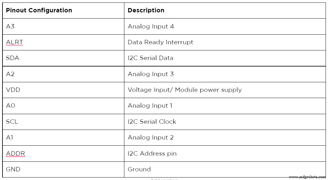
Pin Configuration of The ADS1115
How to interface ADS1115 16-bit ADC with Arduino

Engineering student interfacing ADS1115 to Arduino
Interfacing the ADS1115 to an Arduino isn’t rocket science because it’s an outer digital-analog converter (ADC). No doubt, there are inner ADCs that are perfect for analog inputs for Arduino. But the ADS1115 comes with four 16-bit ADCs with the help of a 12C pin—making it easy to read.
Arduino interfacing with ADS1115
Here, in this section, you’ll see how to link the ADS1115 16-bit ADC to Arduino—with the following steps;
The required tools for this project
- ADS1115 sensor (1)
- Breadboard (1)

- Arduino nano/uno (1)
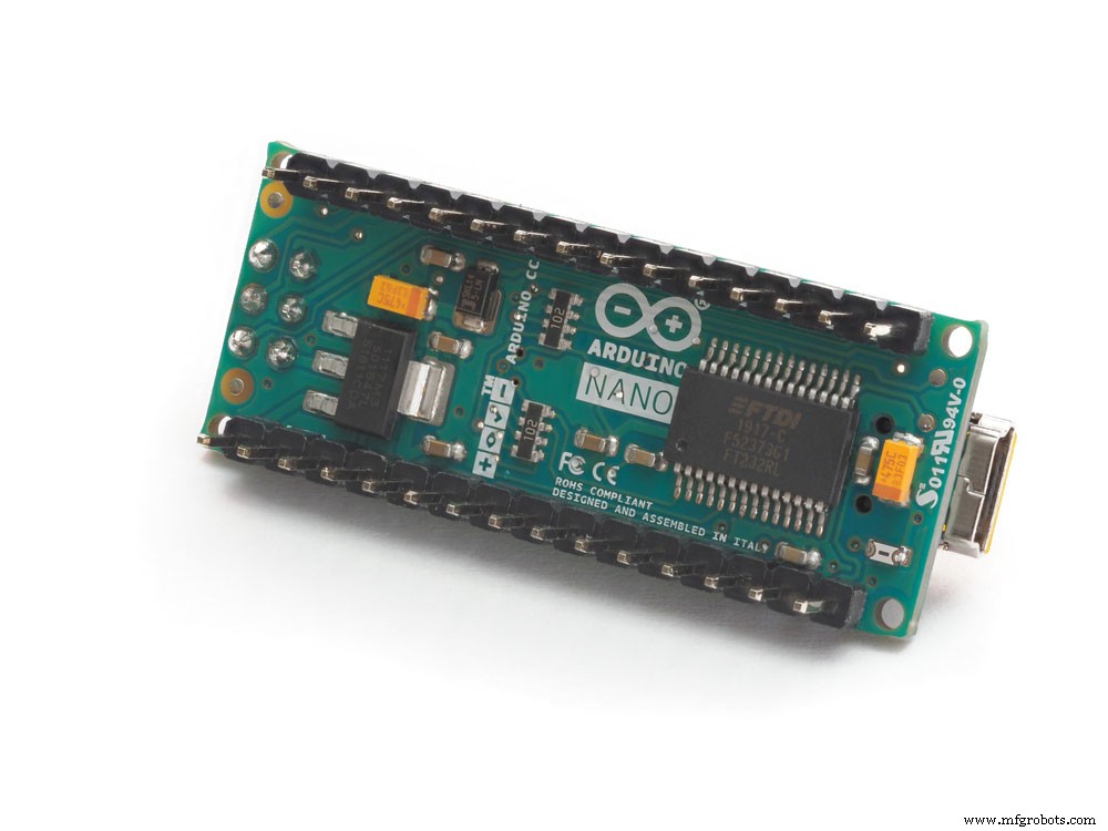
Arduino nano
- Jumper wires (1)
Jumper wires
- i2c Lcd (1)
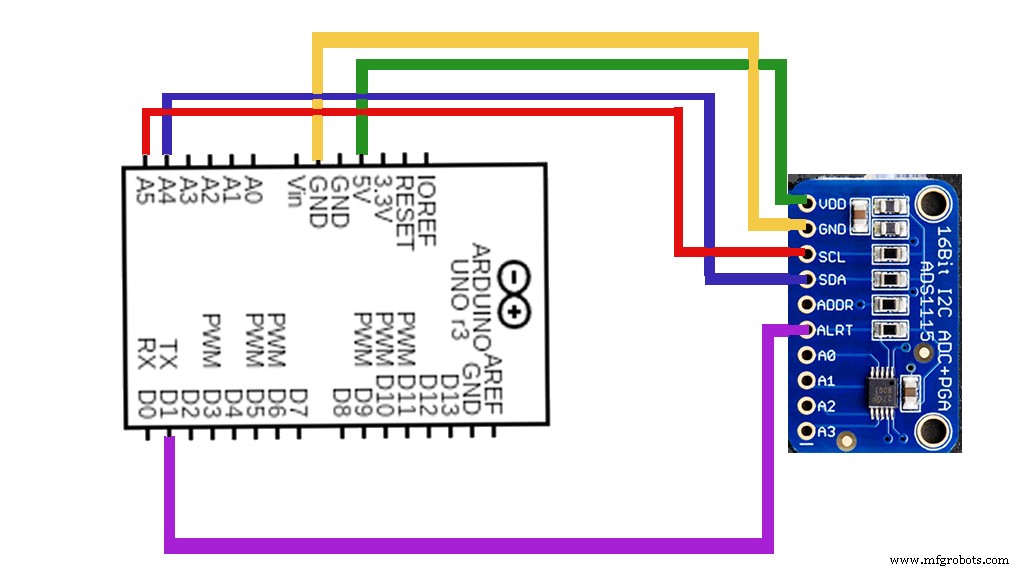
Step One: Schematics
First off, you join the Arduino’s module to the 5 volts and GND. Then, merge the sensor’s resultant pins with the SCL and SDA Arduino pins. Interestingly, the ADDR pin on the Arduino defines the address of the i2C device.
So, the preferred way is to connect the GND and ADDR pin together—resulting in an 0x48 address.
Step Two: Reading Code for ADC (Serial Print)
After making the necessary connections between the Arduino and ADS115, it’s ideal for running the codes for the single-end mode. Here, you’d have to confirm the value per serial port and read the four channels on the board. Next, use the multiplier, which depends on the PGA gain, to switch values to voltage.
To finalize this second step, run the above codes and complete the connections. Then, you’ll get the printed results from the serial monitor after opening it at 9600 bauds. Alternatively, you can use the i2C LCD to download the result codes.
Step Three: Reading Code for ADC (LCD results)
In this section, upload the codes below and finalize the necessary connections. Then, check for the results on the LCD screen or 9600 bauds open serial monitor.
Interfacing ADS1115 16-bit ADC to Raspberry Pi
ADS1115 interfacing with Raspberry Pi
Interfacing Raspberry Pi and ADS1115 are super simple—thanks to the i2c bus.
Hence, here are the quick steps to follow:
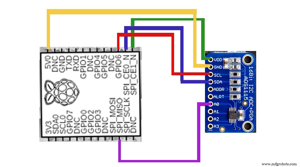
Step one: Wiring
The connection for Raspberry Pi is quite similar to the Arduino. First, connect the VDD of the ADS1115 to the VDD of the Raspberry Pi. Then, the GNDs of both the ADS1115 and the Raspberry Pi together. To conclude, merge the SDA and SCL of the Raspberry Pi to that of the ADS1115.
Step two: Installation from Library
The next step after making the connections is to run the installation of the ADS1115 Python library. We recommend running the installation library with this GitHub source code. Nonetheless, ensure you have stable internet before running the Raspberry Pi library installation.
Step three: Installation from Source
Here’s the code required to run an installation from the source:

Ensure you connect to the Raspberry terminal on Github before installing.
Step four: Phyton Package Installation
Here, ensure to link to the Raspberry terminal on the Phyton index package.
The code required to run the installation includes:

Please note; that you won’t find the library example code if you install it directly from the phyton index package. So, we recommend that you download examples of ADS115 manually to the Raspberry Pi and run them.
Can ADS1115 read negative voltage?
Yes, the ADS1115 can read negative volts even with its single output supply. Plus, it can translate the -ve input voltage to a -ve number.
Closing Words
The ADS1115 module is a reliable device that converts an input analog signal into a digital signal. And it also has a programmable gain amplifier that multiplies little analog signal values by a variable. Consequently, you can get a higher signal value. Thus, the device is effective for battery monitoring systems or comparators.
So, do you have questions or suggestions on the topic? Or do you need the module for your project? Please, feel free to reach us; we’ll be more than happy to help.
Industrial Technology
- Connecting Arduino Mega to a NEO‑6M GPS Module: A Step‑by‑Step Guide
- Track Orientation with Arduino & ADXL345 Accelerometer – A Step‑by‑Step Guide
- Master Rotary Encoders with Arduino: How They Work & Step‑by‑Step Integration
- Arduino Explained: What It Is and How to Program It
- Connecting the DS1307 Real‑Time Clock to Arduino: A Step‑by‑Step Guide
- Light Intensity Sensors: Features, Uses, and Arduino Integration Guide
- Arduino SD Card 101: Setup, Connection, and Usage Guide
- STM32 Nucleo: Features, Connectivity, and PC Integration
- HC-SR04 Ultrasonic Sensor Explained: Working Principles and Arduino Integration
- MCP9808 Temperature Sensor: A Complete Arduino I2C Integration Guide