


Understanding the Four EV Charging Modes in IEC 61851: A Comprehensive Guide
Exploring IEC 61851: The Four Key EV Charging Modes
Global electric‑vehicle adoption hinges on robust international standards that ensure safety, reliability, and seamless interoperability. The IEC 61851 standard, focused on conductive charging systems, defines four distinct charging modes—1 through 4—each tailored to specific use cases and safety requirements.
Other IEC documents complement this framework: IEC 62196 covers plugs, socket‑outlets, vehicle connectors, and inlets, while IEC 61980 addresses wireless power transfer (WPT) systems. Together, they form a comprehensive ecosystem for EV charging technology.
Types of Cable Connections
IEC 61851‑1 classifies cable connections into three categories, illustrated below:
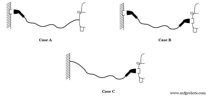
The three primary EV charging cable configurations. Image courtesy of the University of Zagreb.
• Case A – Cable permanently attached to the EV, detachable at the charging station (EVSE). • Case B – Cable detachable at both ends. • Case C – Cable permanently attached to the EVSE.
EV Charging Mode 1
Mode 1 connects the EV directly to a household socket. It supports a maximum current of 16 A, with voltage limits of 250 V for single‑phase and 480 V for three‑phase systems. This mode lacks communication between the EV and the charging point, and is often prohibited or restricted in many jurisdictions.
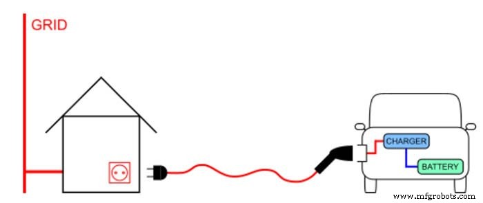
Basic connection of an EV to a household socket. Image courtesy of the University of Zagreb.
EV Charging Mode 2
Household outlets are not designed for continuous high‑current loads typical of EV charging. Mode 2 introduces an in‑cable control and protection device (IC‑CPD) that manages safety functions such as earth‑connection detection, over‑current, and over‑temperature protection. It supports a maximum current of 32 A and voltage limits identical to Mode 1, and can be used with both household and industrial sockets. However, many countries restrict its public use.
Key safety features include:
- Continuous monitoring of the protective earth connection.
- Automatic over‑current and over‑temperature shutdowns.
- Functional switching by the EVSE based on detected power demand.
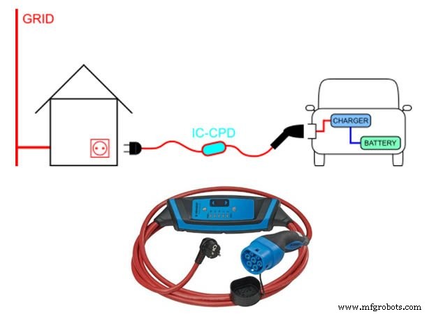
Mode 2 charging cable with IC‑CPD. Image modified by University of Zagreb and Ali Bahrami.
EV Charging Mode 3
Mode 3 employs a dedicated EVSE and an on‑board charger to deliver AC power to the battery. It incorporates comprehensive safety and communication protocols, ensuring both the EV and EVSE are fully synchronized before charging commences. The mode can supply up to 250 A on either 250 V single‑phase or 480 V three‑phase systems, and also supports a reduced 32 A limit for compatibility with Mode 2 scenarios.
All cable connection types (Case A, B, C) are permissible, with Case B and C illustrated below:
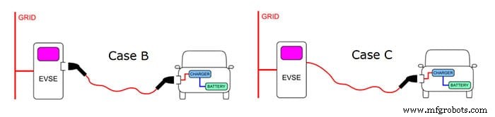
Case B and C in Mode 3. Image courtesy of the University of Zagreb.
The control pilot circuit—central to Mode 3’s communication—operates as follows:
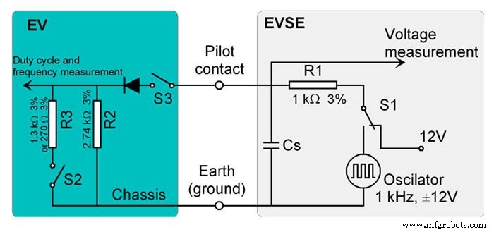
Control pilot circuit of Mode 3. Image modified by Energies.
Switches S1, S2, and S3 modulate the pilot voltage to signal different charging states:
- Before cable connection: S2 and S3 off, S1 active → 12 V DC indicates no connection.
- After cable connection: S3 on → 9 V signals cable attached but EVSE not ready.
- EVSE ready: S1 to oscillator → PWM indicates readiness.
- EV ready: S2 on → 6 V (or 3 V with R3 = 270 Ω) signals readiness and ventilation requirement.
- Charge abort: S2 off → 9 V signals termination.
EV Charging Mode 4
Mode 4 is unique in delivering high‑power DC directly to the battery, bypassing the on‑board charger. It can supply up to 600 V DC at 400 A, necessitating advanced communication and stringent safety mechanisms. Only Case C connections—permanently attached cables—are permitted for this mode.
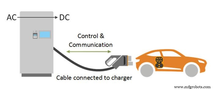
Mode 4 in a Class C connection. Image courtesy of Ali Bahrami.
Conclusion
The IEC 61851 standard delineates four charging modes that cover the full spectrum of EV conductive charging—from basic household connections to high‑power DC injection. Modes 1–3 feed AC power into the vehicle’s on‑board charger, while Mode 4 supplies DC directly to the battery. Mode 3’s sophisticated control pilot system exemplifies the standard’s commitment to safety and interoperability.
Industrial Technology
- Mastering Product Leadership: The Four Essential Pillars
- Celebrating 30 Years of MEP: Reflecting on Four Key Manufacturing Eras
- How Blockchain Transforms the Global Food Supply Chain: 4 Key Benefits
- 4 Proven Strategies to Thrive in the New E‑Commerce Landscape
- Standard Procedure for Comprehensive Work Equipment Inspection
- Maximize Power, Minimize Fuel: Volvo Excavators’ Single-Dial Work Mode
- Exploring Four Key Growth Opportunities for the Aluminium Industry
- Calculate Battery Charging Time & Current: Step‑by‑Step Guide with 120Ah Example
- Integrating ISO 9001 into Manufacturing Strategy: Driving Quality and Growth
- Mitigating Risks When Converting Standard to Metric Tolerance Charts