


Preventing Warpage in Injection‑Molded Parts: Design Strategies
In this fourth installment of our injection‑molded part series, we focus on a common yet often overlooked defect: warpage. Warpage arises from differential cooling across a freshly molded part, typically caused by uneven wall thickness, internal features, or complex aspect ratios. While 3‑D mold‑flow analysis can predict many of these issues, real‑world factors such as material flow during cooling and post‑molding stress relief can amplify predicted distortions, making warpage a critical concern for both performance and aesthetics.
Even a modest amount of predicted warpage can evolve into a pronounced bend during the part’s cooling cycle. This is especially problematic for products that must meet tight fit‑up or aesthetic criteria—such as high‑gloss painted housings where even minor sagging produces fish‑eye reflections. In prototype stages, where machined or printed mock‑ups are used, warp may not be evident until actual injection molding is performed.
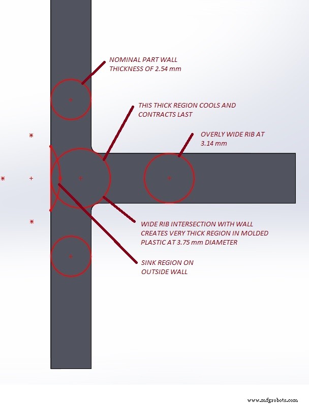
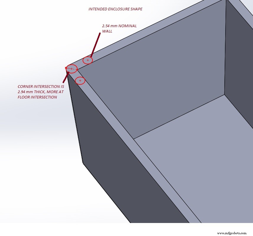
To mitigate warpage, begin with consistent wall thickness and gentle transitions. Maintain gradual rib and boss tapering, and consider increasing corner radii on the outside to keep the inner fillet thickness uniform. If a sharp exterior appearance is required, introduce internal cores at corners to locally thin the material while preserving a constant wall thickness around the fillet.
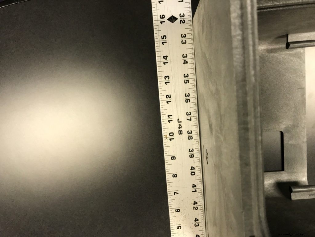
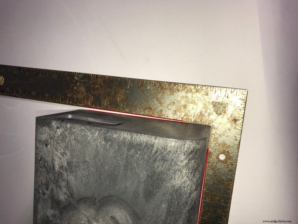
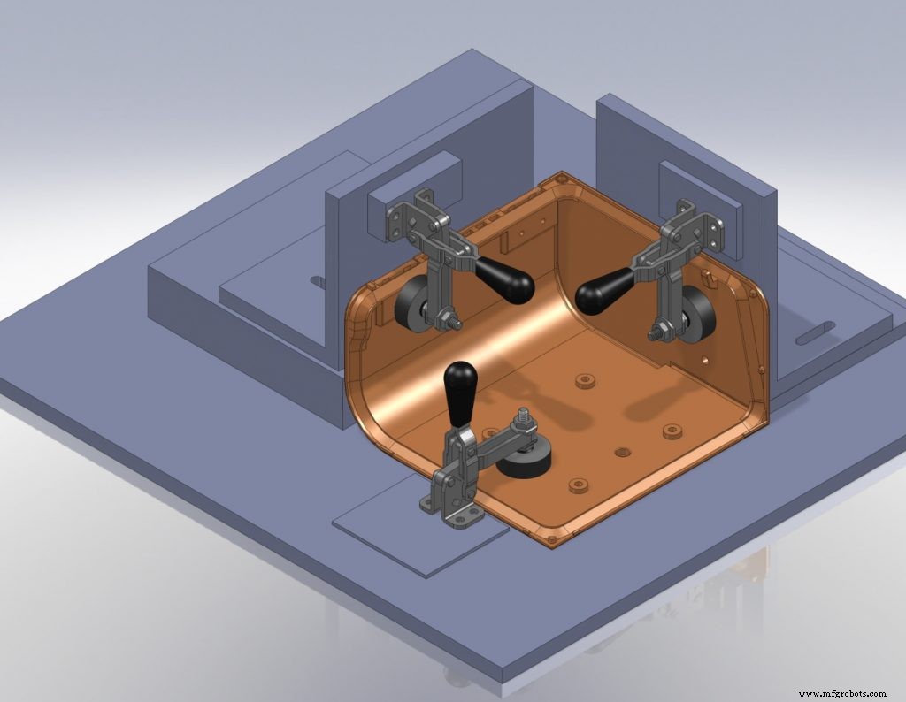
Large flat surfaces present their own challenges. A single sag or dip becomes highly visible under a shiny finish, as demonstrated in the Protein Simple lab‑equipment line, where the initial door part warped out of square. By collaborating closely with the mold house and employing custom post‑molding fixtures, the team achieved near‑perfect planarity without additional hand finishing. The result was a design award and a six‑fold sales increase in the first month.
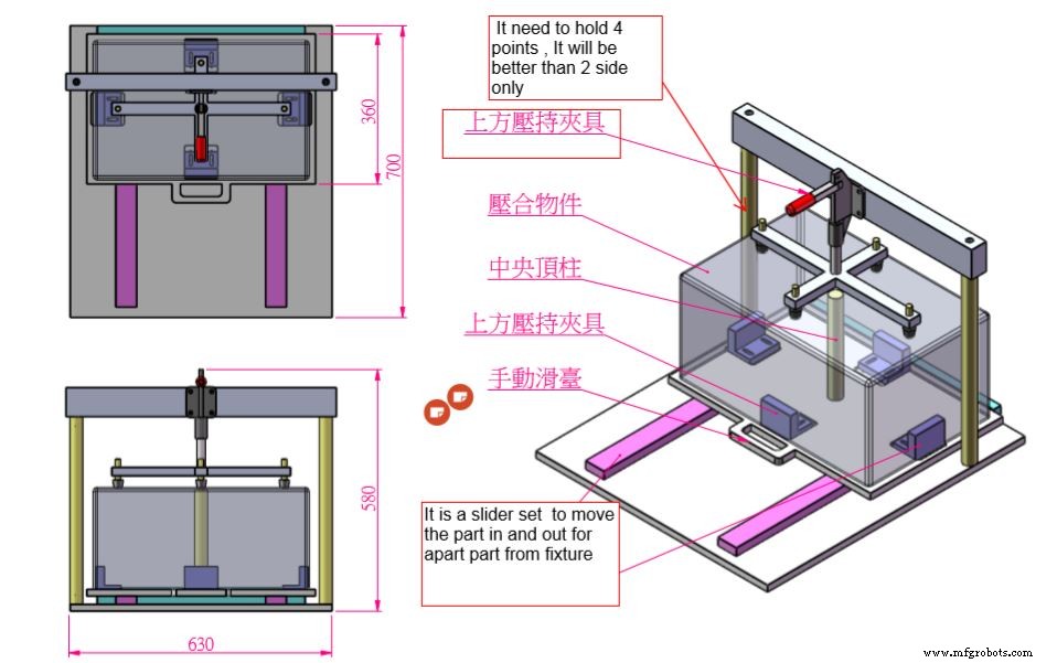
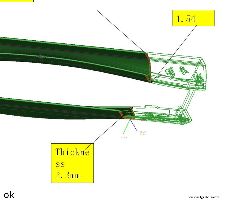
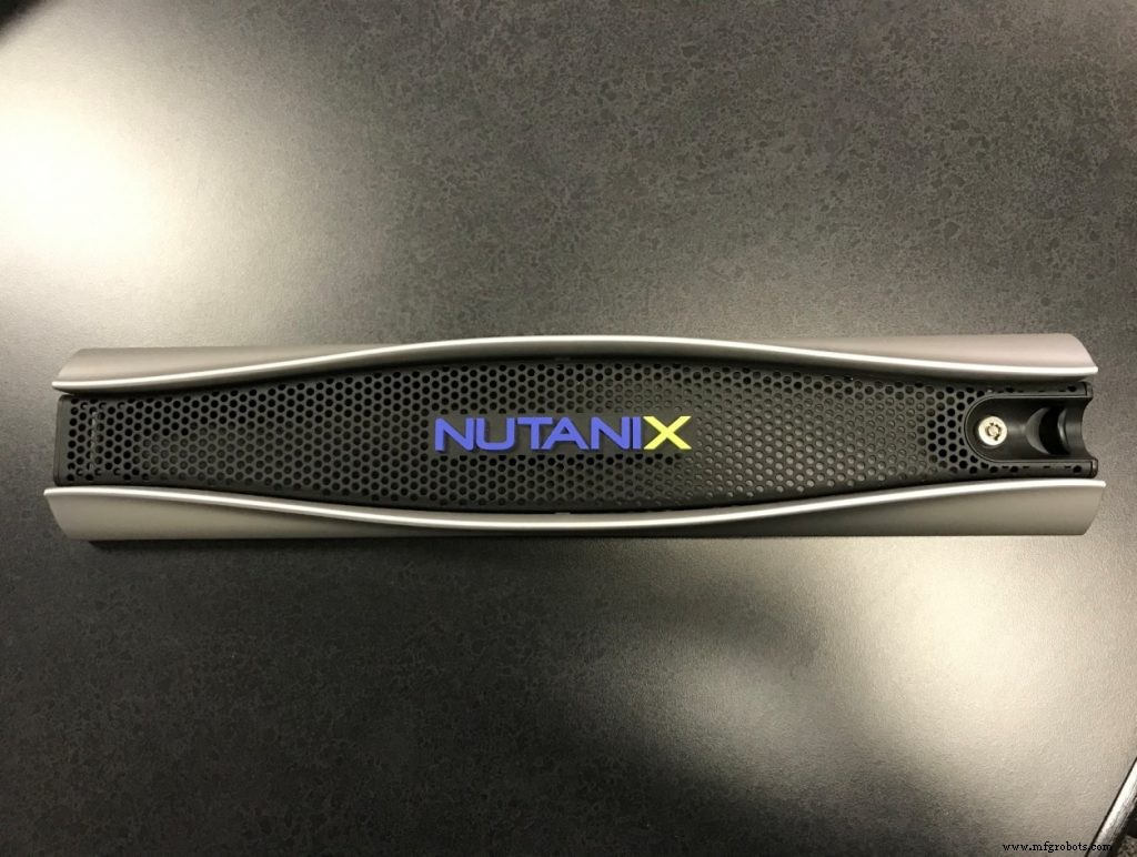
When parts feature large openings or thin spans—common in bezel designs for rack‑mounted servers—warpage can become even more pronounced. The bridge‑like sections that satisfy venting or access needs are especially susceptible. In such cases, fine‑tuning material thickness, reinforcing transitions, and employing post‑molding fixtures are essential. Close collaboration with the molding team, along with iterative mold‑flow analysis and physical testing, can resolve these issues efficiently.
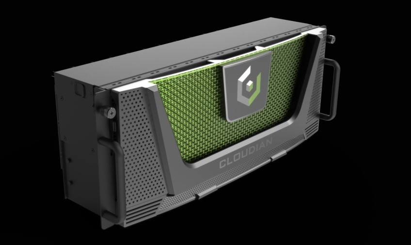
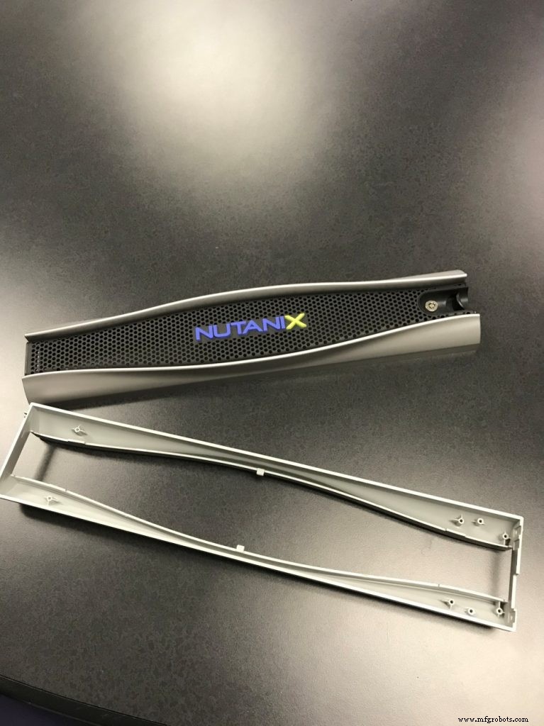
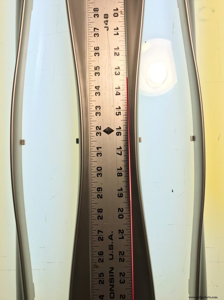
In many instances, the only structural support available is a removable metal perforation that cannot reliably bear the stresses imposed by warpage. The solution lies in rigorous design review, material selection, and post‑molding fixture development, which collectively deliver high‑quality components that meet both functional and branding goals.
In summary, warpage is a design‑phase concern that can be mitigated through thoughtful geometry, consistent wall thickness, and proactive collaboration with the molding team. By following these guidelines, designers can create injection‑molded parts that not only perform flawlessly but also uphold the brand’s visual standards.
See More Like This: Undercuts, Sink Marks, Bosses
Manufacturing process
- Part 6: Managing Teams & Contract Manufacturers in Injection Molded Part Design
- Injection Molding Part Design: Mastering Draft Angles for Seamless Ejection
- Designing Injection Molded Bosses: Balancing Strength and Molding Success
- Injection Mold Design – Part 2: Understanding and Eliminating Sink Marks
- The Critical Role of Draft Angles in Injection Molding Success
- 6 Proven SLA Design Tips for Flawless 3D Print Quality
- Expert Guide: Eliminating Undercuts in Injection Molding for Seamless Part Release
- Avoid These 4 Common Design Pitfalls in Injection Molding
- Enhance Your Parts with Custom Injection Molding Features
- Advanced Aircraft Design: Part 2 – Expanding Horizons with Efficient Modeling