


Designing Injection Molded Bosses: Balancing Strength and Molding Success
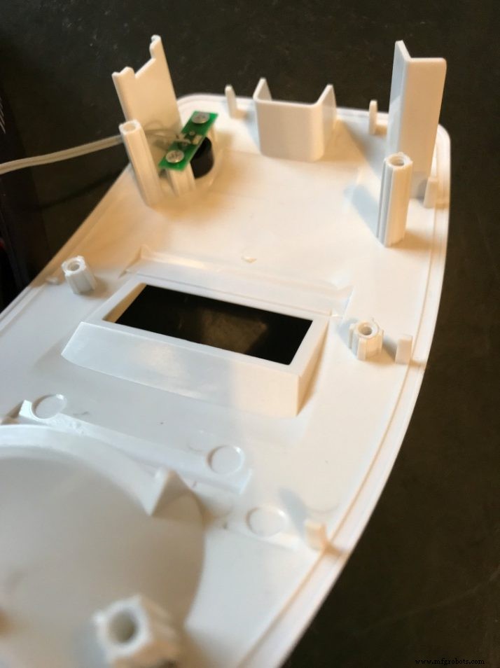
Injection‑molded parts are an excellent choice for medium‑to‑high volume products. When the design incorporates molded plastic bosses, you can achieve a low‑cost solution that aligns components and provides robust mounting points for fasteners and enclosures. However, careful design and placement of these bosses are essential to avoid cosmetic defects and ensure reliable structural performance.
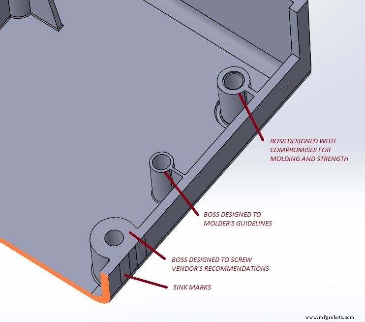
Many design guidelines exist for creating bosses, yet they often conflict. Recommendations vary by manufacturer, contract molder, assembly team, or industrial designer. The key is to merge these perspectives into a boss that performs without introducing visible cosmetic flaws. Achieving this balance requires collaboration between the mechanical engineer and the injection‑molding partner, who will refine the process and ensure part quality.
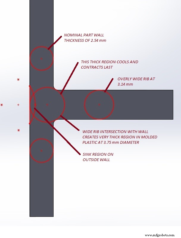
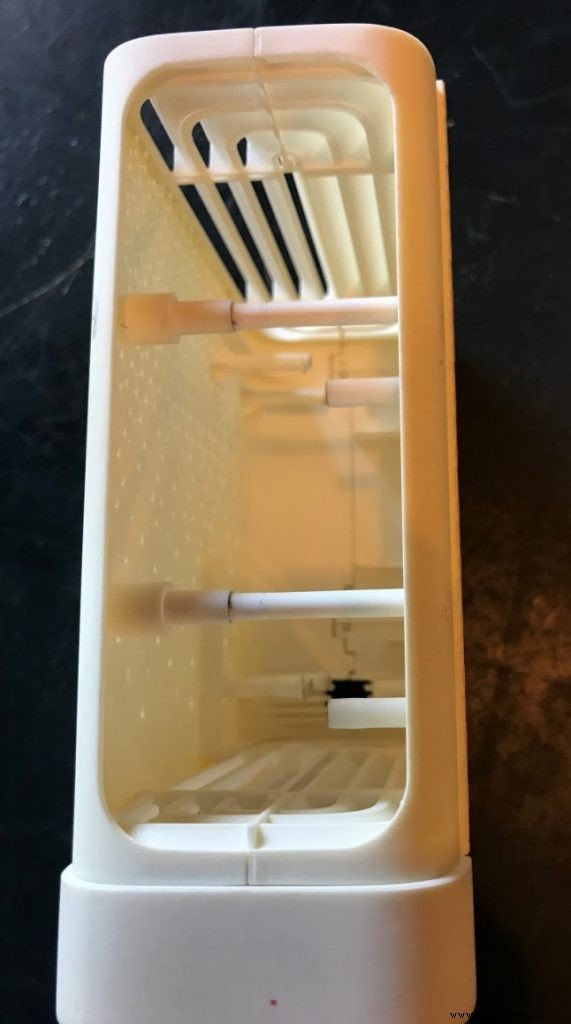
Why do bosses sometimes fail? An oversized or poorly positioned boss can create sink marks on key cosmetic surfaces. In injection molding, a sink occurs when a thick section of plastic—typically at the intersection of internal features and outer walls—cools more slowly than the surrounding material. The slow‑cooling core contracts against the already rigid plastic, producing dimples, surface stress, and sometimes warpage. These defects can also hinder proper filling of the mold, leading to additional flaws.
Conversely, an undersized boss may be easy to mold but fails to retain fasteners, causing components to loosen or even cause part rejection. The boss must provide sufficient wall thickness to absorb installation forces and to support the threaded fastener. If the material is too thin, it may cold‑flow during assembly, leading to loosening or failure under load.
In addition, bosses require draft to allow ejection from the steel mold. The outer diameter walls grow at the base, often with a slight fillet for smooth ejection. Treat the boss as a circular rib: its wall thickness should be about 50–60 % of the nominal wall thickness of the surrounding part to prevent sink. Achieving this ratio while still providing enough material for a robust joint is the core challenge.
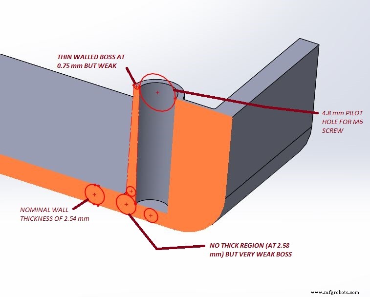
For screws in plastic, it is recommended that the thread engagement depth be 2 to 2.5 times the nominal screw diameter. This higher engagement compensates for the typically lower shear strength of plastic compared to metal. Proper thread depth spreads joint stresses and enhances durability.
To reconcile strength with moldability, consider the following proven design strategies:
- Reduce the boss’s outer diameter relative to the manufacturer’s recommendation, keeping the wall thickness close to the surrounding plastic.
- Apply minimal draft on interior surfaces while maintaining a smooth, filleted base.
- Position the boss away from critical outer walls to avoid large intersecting volumes.
- Deepen the pilot bore by approximately 30 % of the nominal base thickness, which reduces the intersection area and allows for thicker boss walls.
- Incorporate a shallow trough at the boss base to further limit thick sections.
- Use a taller, well‑designed boss with a landing wall covered by an adjoining slip‑over part for added strength.
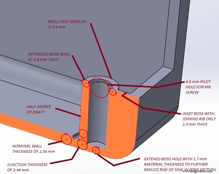
These techniques keep the boss within the safe wall‑thickness range (50–67 % of nominal), improve thread engagement, and minimize sink risks. During the first production run, evaluate the boss and fastener performance; plastic alloy changes or design tweaks can be accommodated by adjusting the mold pin or adding material—actions that are generally straightforward and inexpensive.
Ultimately, each part’s requirements dictate the optimal balance. Functional components that are not visible can tolerate minor cosmetic defects if they do not compromise strength. By working closely with the molding partner—adjusting cycle time, cooling, and process parameters—you can eliminate minor sinks and refine the part to meet both aesthetic and mechanical goals.
For a deeper dive, see Part 1, Part 2, and Part 4.
Manufacturing process
- Part 6: Managing Teams & Contract Manufacturers in Injection Molded Part Design
- Injection Molding Part Design: Mastering Draft Angles for Seamless Ejection
- Preventing Warpage in Injection‑Molded Parts: Design Strategies
- Injection Mold Design – Part 2: Understanding and Eliminating Sink Marks
- The Critical Role of Draft Angles in Injection Molding Success
- 6 Proven SLA Design Tips for Flawless 3D Print Quality
- Expert Guide: Eliminating Undercuts in Injection Molding for Seamless Part Release
- Avoid These 4 Common Design Pitfalls in Injection Molding
- Enhance Your Parts with Custom Injection Molding Features
- Mastering Screw Boss Design for Durable Molded Parts