


Designing Transparent Plastic Components for Optimal Performance
Designing Transparent Plastic Components for Optimal Performance
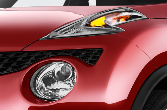
Recent years have seen a surge in products that feature clear plastic elements to enhance user interaction, reveal internal mechanisms, showcase lighting effects, or simply add a distinctive aesthetic. While some manufacturers are willing to invest heavily to achieve exceptional optical clarity, many others overlook the nuanced design decisions that translate early renderings into production‑ready parts.
Proactive dialogue with the product development team can clarify expectations and outline the steps required to deliver transparent parts that meet both visual and functional goals without inflating costs.
Transparent parts that are not intended as optical elements or instrument windows still present challenges. Unlike opaque or textured components, they exhibit a glossy finish that exposes internal molding artifacts—ejector marks, flow lines, and weld lines that would otherwise remain hidden.

Begin by defining the true expectations for the clear part. If the component is not a primary visual feature or if a subtle frosting is acceptable to diffuse light, the clarity and surface quality requirements may be comparable to non‑transparent parts. However, if the clear area is front‑and‑center, the tolerance for visual imperfections must be considerably tighter. Consider the part’s function—does it also mount internal components, seal housings, or serve as a structural element? Additional internal features can degrade look‑through quality. Simplifying the clear surface or separating it into a dedicated, minimal‑feature part can mitigate these issues. Finally, assess whether the clear feature adds real value or simply inflates cost.
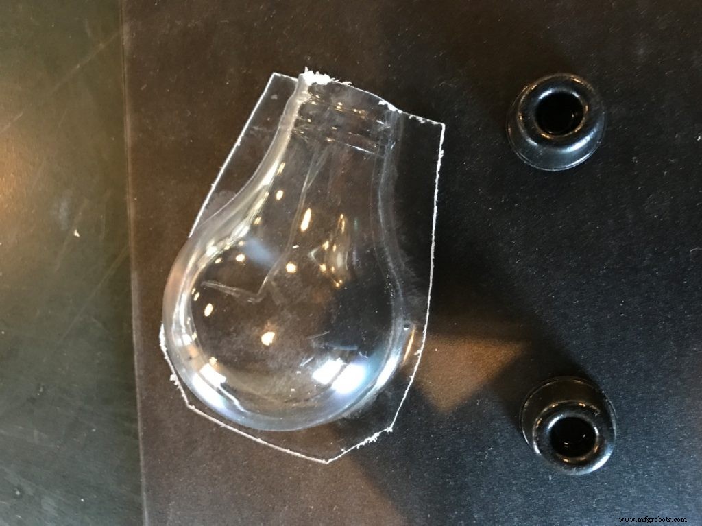
Once the clear parts are defined, look for opportunities to simplify the geometry without compromising aesthetics. Large transparent components are inherently more difficult to mold because they tend to include internal features and ejector marks. Ejectors, which push the part out of the mold, leave small circular marks around their edges.

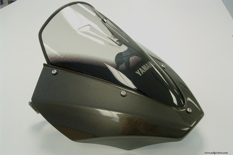
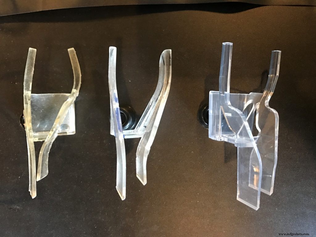
In many cases, replacing the molded surface with a clear sheet—acrylic or polycarbonate—provides a clean integration point. Injection‑molded clear panels can be costly and time‑consuming, as they are prone to defects that increase yield loss. Sheet material, when flat or bent around a single axis, offers consistent clarity and lowers production risk. For designs that demand complex curvature or multi‑axis bends, vacuum or pressure forming of a clear sheet can produce a near‑perfect shape while avoiding the flow‑related imperfections of molding.

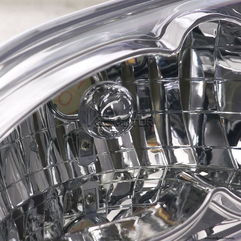
If injection molding is unavoidable, aim for the simplest geometry possible. Even with perfect flow simulation, large or irregular thickness transitions can create sink marks or unwanted light‑bending effects. Avoid heavy ribbing or undercut bosses inside the clear area; such features act like lenses and amplify any imperfections. Companies like Apple have invested significant effort to fine‑tune internal geometry so that the visible result remains flawless, justifying the premium price of the final product.
Additional attention is required for draft angles. Draft—the taper in the mold walls that allows the part to be ejected—must be carefully designed to prevent scraping or visible scratches on the clear surface. Side actions and lifters that accommodate undercuts can leave subtle marks; these are particularly noticeable on transparent parts. Collaborate early with the mold tooling team to ensure the design accommodates these constraints.
When the clear part functions as a light guide or indicator, prototype early and iterate. Even simple light‑pipe geometries can be difficult to perfect; larger diffused lighting often requires many iterations. Include the electrical engineering team in discussions to select the appropriate number, type, and adjustability of light sources. A poorly engineered lighting circuit can negate the visual impact of an otherwise flawless transparent component.

In short, go transparent—just be sure to address the details from day one. With careful coordination across design, tooling, and electrical teams, you can deliver a clear part that enhances product appeal while staying on schedule and budget.
Manufacturing process
- Rapid Prototyping of a Bike‑Mounted Fishing Rig: From CAD to the Water
- Designing Thermoset Composite Parts: A Practical Guide & Infographic
- Defining Clarity in Plastics: How Scientists Measure True Transparency
- The Definitive Checklist for Purchasing Plastic Fasteners
- Master CNC Machining: Proven Design Strategies for Optimal Parts
- Master CNC Part Design: Expert Tips & Techniques
- Designing Clear Parts: Materials, Techniques, and Finishing for Transparent and Translucent Components
- The Complete Guide: Transforming Raw Plastic Resins into Finished Products
- Optimize 3D-Printed Parts with Generative Design: A Practical Guide
- Expert Clear Plastic Injection-Molded Parts: Precision & Clarity