


Servo‑Driven Obstacle‑Avoiding Robot: Build with Arduino & HC‑SR04
Components and supplies
 |
| × | 1 | |||
 |
| × | 1 | |||
 |
| × | 1 | |||
| × | 1 | ||||
 |
| × | 1 | |||
 |
| × | 1 |
Necessary tools and machines
 |
|
Apps and online services
 |
|
About this project
All about the project
I'm a Media Arts Design student who study in Multimedia University, Cyberjaya Malaysia. This is my Gamma Year of studying Media Art, Interaction Design is the subject that will teach students on how to use Arduino components and how it works. So in my final assignment, I have choosed Obstacles Avoiding robot as my own project and learn how every components works.
Step 1:
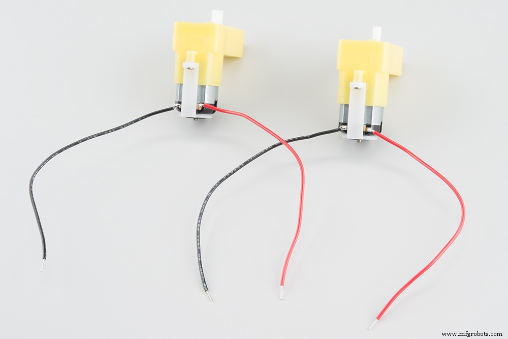
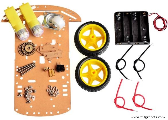
Prepare and build your Robot chasis. Inside the package have a few components, chassis, two motors, two wheels, a front wheel, a battery holder, some screws, switch and jumper wires. Photo below:
Step 2:
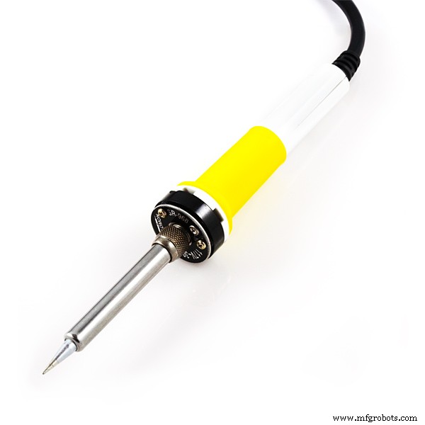
Before solder the jumper wires on your both motor, I would recommend to test every components for make sure they all are working well, example: Both DC motors, Arduino board, Motor Shield, Servo motor and Ultrasonic sensor. Then we will start solder the red and black wire on both motors, example picture below:

Step 3:
Come to our battery chassis and switch part. We only need to cut half of the black wire from the battery chassis and solder 1 wire side at 1 hole, another black wire will solder at another hole. Our switch is ready!
Step 4:
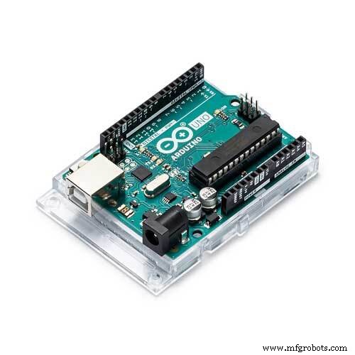
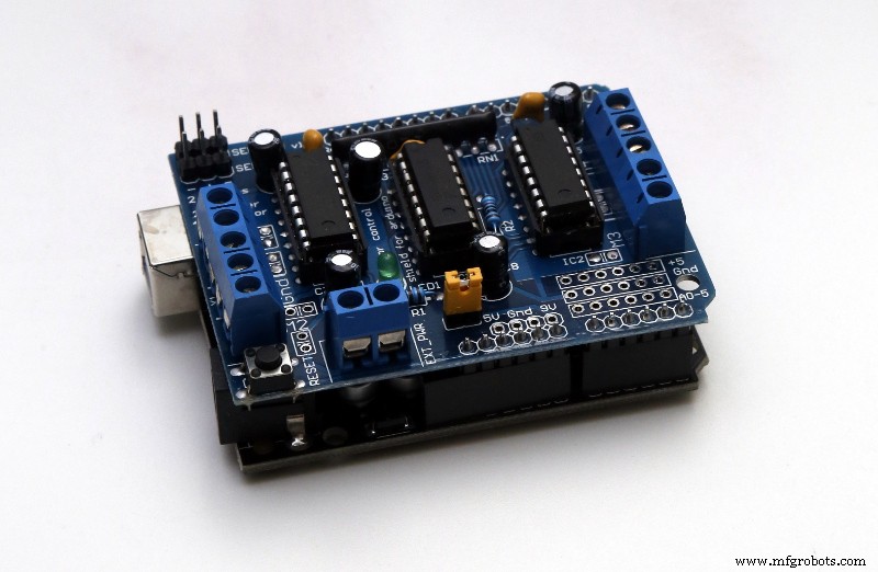
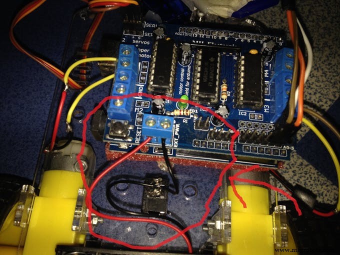
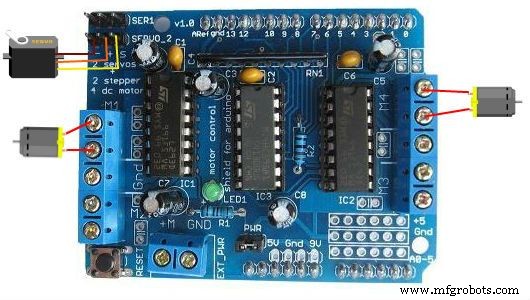
We will need to stack Arduino board and Motor Shield board, Motor Shield will stack on Arduino board. Example below:
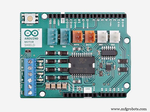
Step 5:
We will move on to the Motor Shield board. This shield provides power to the motors and the servo motor, the motors need a lot of current, and this shield can provide up to 600mA of current to each motor. We need to solder/fixed the DC motors wires at the Motor shield board. If the your DC motor wires are long enough to reach the Motor Shield will be great, if not you might need to use external jumper wires(No matter is Male/Female jumper wire), cut off the jumper wire head and make sure inside the copper line shows up. (You will need to cut jumper wire rubber to make the copper wire appear). And you need to solder the external wires to the DC motor wires. Example:
Then connect the left motor wire to M1 connector of the motor shield. Right motor wire will coneect to M3 connector from the Motor shield board. Example:
Step 6:
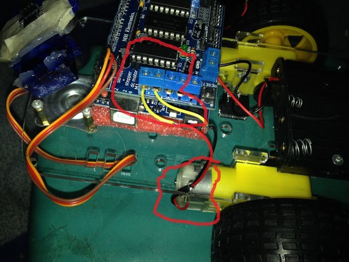
Then we will need to connect the battery switch wires both red and black wire to the Motor shield board.
After that, we will need to ready Male and Female jumper wires for solder them to 5V, GND, Analog Pin 4 and Analog Pin 5. Before that, we will need to find same colors of female and male jumper wires and cut them into half. Why must be same color? First is easy for us to recognize which wire are for which part. Second, white Male jumper wire will solder with white Female jumper wire which connect to 5V. Black color Male jumper wire will solder with female jumper wire and Male jumper wire will solder to GND. Orange color Male jumper wire will solder with orange Female jumper wire, Orange male jumper wire will solder at Analog Pin 5. Lastly but not least, brown male jumper wire will solder with female brown jumper wire, then brown color male jumper wire will solder to Analog Pin 4. Example:
Step 7:
You are able to use double sided tape or hot glue gun for attach the both shield on the robot chassis.
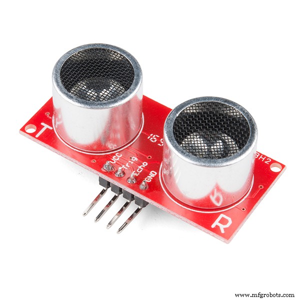
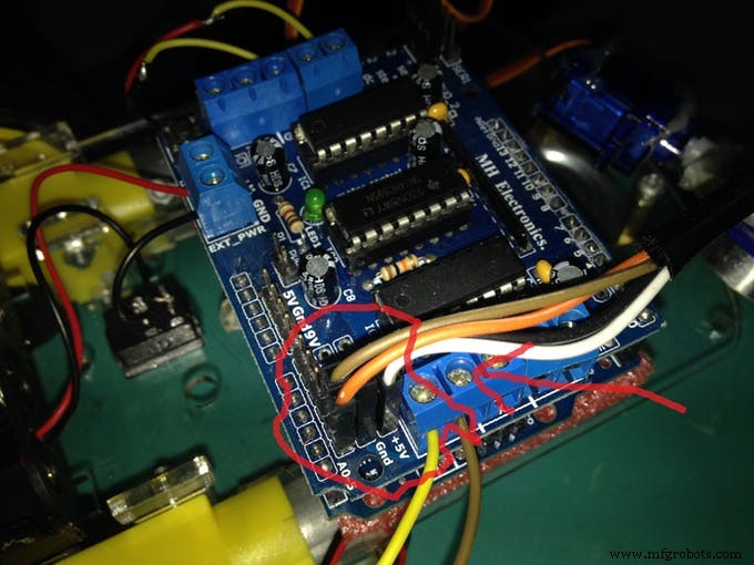
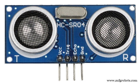
Step 8: Come to Ultrasonic Sensor part
From the Female & Male jumper wires that we solder just now, White jumper wire(5V)(Female site jumper wire) will connect to Ultrasonic Sensor VCC pin. Black Jumper wire(GND)(Female site jumper wire) will connect to GND pin. Brown jumper wire(Analog Pin 4)(Female site jumper wire) will connect to Echo pin. Orange color jumper wire(Analog Pin 5)(Female site jumper wire) will connect to TRIG pin.
Step 9:
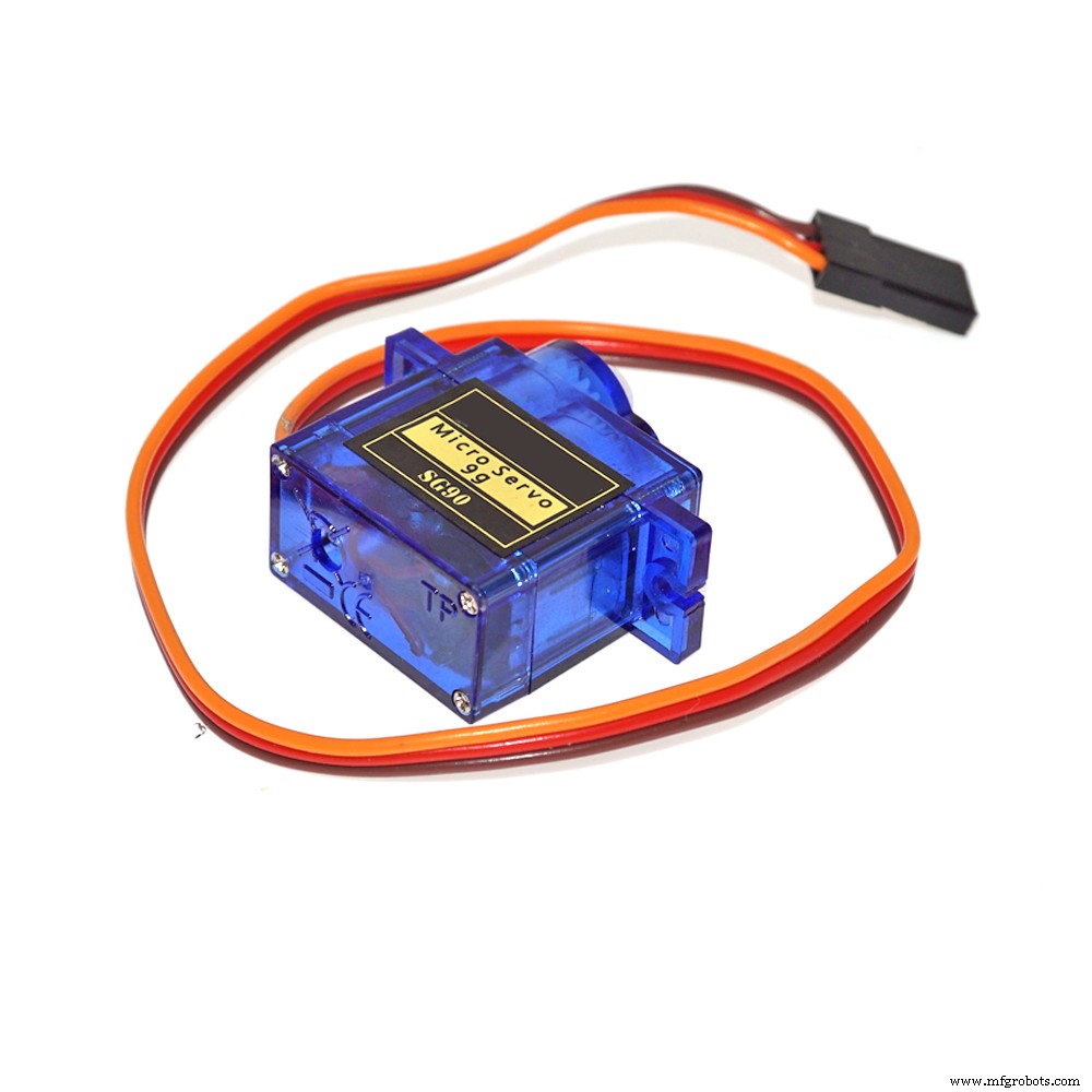
Lastly, For the Servo motor will connect to servo_2 slot. Note* (There are few types of servo motor out there. you might need to find it online for how they plug to servo_2 slot). Below is for my own version of servo slot.
Last Step: Code
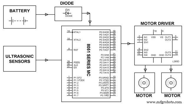
For this Obstacles avoiding robot, we will need 3 libraries, which is Motor Shield library for Motor Shield driver, New Ping library is for the Ultrasonic Sensor. Third is Arduino IDE. Below are the downloadable links for libraries:
Motor Shield Library
- New Ping Library
I'm appreciate for you guys to view my project. I hope the instructions are clear enough for you guys to follow and build the Obstacles Avoiding Robot for yourself. Thank you!
Video for testing:
Code
- Arduino IDE
Arduino IDE C#
Copy and Paste the code in Arduino IDE then upload to your Arduino board#include <AFMotor.h>
#include <Servo.h>
#include <NewPing.h>
#define TRIG_PIN A4
#define ECHO_PIN A5
#define MAX_DISTANCE_POSSIBLE 1000
#define MAX_SPEED 150 //
#define MOTORS_CALIBRATION_OFFSET 3
#define COLL_DIST 20
#define TURN_DIST COLL_DIST+10
NewPing sonar(TRIG_PIN, ECHO_PIN, MAX_DISTANCE_POSSIBLE);
AF_DCMotor leftMotor(3, MOTOR12_8KHZ);
AF_DCMotor rightMotor(1, MOTOR12_8KHZ);
Servo neckControllerServoMotor;
int pos = 0;
int maxDist = 0;
int maxAngle = 0;
int maxRight = 0;
int maxLeft = 0;
int maxFront = 0;
int course = 0;
int curDist = 0;
String motorSet = "";
int speedSet = 0;
void setup() {
neckControllerServoMotor.attach(10);
neckControllerServoMotor.write(90);
delay(2000);
checkPath();
motorSet = "FORWARD";
neckControllerServoMotor.write(90);
moveForward();
}
void loop() {
checkForward();
checkPath();
}
void checkPath() {
int curLeft = 0;
int curFront = 0;
int curRight = 0;
int curDist = 0;
neckControllerServoMotor.write(144);
delay(120);
for(pos = 144; pos >= 36; pos-=18)
{
neckControllerServoMotor.write(pos);
delay(90);
checkForward();
curDist = readPing();
if (curDist < COLL_DIST) {
checkCourse();
break;
}
if (curDist < TURN_DIST) {
changePath();
}
if (curDist > curDist) {maxAngle = pos;}
if (pos > 90 && curDist > curLeft) { curLeft = curDist;}
if (pos == 90 && curDist > curFront) {curFront = curDist;}
if (pos < 90 && curDist > curRight) {curRight = curDist;}
}
maxLeft = curLeft;
maxRight = curRight;
maxFront = curFront;
}
void setCourse() {
if (maxAngle < 90) {turnRight();}
if (maxAngle > 90) {turnLeft();}
maxLeft = 0;
maxRight = 0;
maxFront = 0;
}
void checkCourse() {
moveBackward();
delay(500);
moveStop();
setCourse();
}
void changePath() {
if (pos < 90) {lookLeft();}
if (pos > 90) {lookRight();}
}
int readPing() {
delay(70);
unsigned int uS = sonar.ping();
int cm = uS/US_ROUNDTRIP_CM;
return cm;
}
void checkForward() { if (motorSet=="FORWARD") {leftMotor.run(FORWARD); rightMotor.run(FORWARD); } }
void checkBackward() { if (motorSet=="BACKWARD") {leftMotor.run(BACKWARD); rightMotor.run(BACKWARD); } }
void moveStop() {leftMotor.run(RELEASE); rightMotor.run(RELEASE);}
void moveForward() {
motorSet = "FORWARD";
leftMotor.run(FORWARD);
rightMotor.run(FORWARD);
for (speedSet = 0; speedSet < MAX_SPEED; speedSet +=2)
{
leftMotor.setSpeed(speedSet+MOTORS_CALIBRATION_OFFSET);
rightMotor.setSpeed(speedSet);
delay(5);
}
}
void moveBackward() {
motorSet = "BACKWARD";
leftMotor.run(BACKWARD);
rightMotor.run(BACKWARD);
for (speedSet = 0; speedSet < MAX_SPEED; speedSet +=2)
{
leftMotor.setSpeed(speedSet+MOTORS_CALIBRATION_OFFSET);
rightMotor.setSpeed(speedSet);
delay(5);
}
}
void turnRight() {
motorSet = "RIGHT";
leftMotor.run(FORWARD);
rightMotor.run(BACKWARD);
delay(400);
motorSet = "FORWARD";
leftMotor.run(FORWARD);
rightMotor.run(FORWARD);
}
void turnLeft() {
motorSet = "LEFT";
leftMotor.run(BACKWARD);
rightMotor.run(FORWARD);
delay(400);
motorSet = "FORWARD";
leftMotor.run(FORWARD);
rightMotor.run(FORWARD);
}
void lookRight() {rightMotor.run(BACKWARD); delay(400); rightMotor.run(FORWARD);}
void lookLeft() {leftMotor.run(BACKWARD); delay(400); leftMotor.run(FORWARD);}
Schematics
Manufacturing process
- Simple Pi Robot – Build a 2‑WD Autonomous Rover with Raspberry Pi
- Create an Autonomous Line-Following Robot with Arduino UNO
- Arduino & MPU6050: Precise Servo Motor Control with SG90 & MG996R
- Build an Autonomous Home Assistant Robot: Full Parts List & Setup Guide
- Build a 4-Wheel Arduino Robot Controlled via Dabble App
- Smart Indoor Navigation Robot Kit for Arduino Projects
- Build Your Own AI Assistant Robot Using Arduino & Python
- Build a LEGO Wall‑E Robot with Arduino Nano: A Step‑by‑Step Guide
- Arduino‑Powered Robot Arm with Custom Controller – Servo & Potentiometer Build
- Remote Control of a 6‑DOF Arduino Robot Arm via Web Interface