


Custom Arduino TV Remote – Battery‑Powered, 3D‑Printed Case
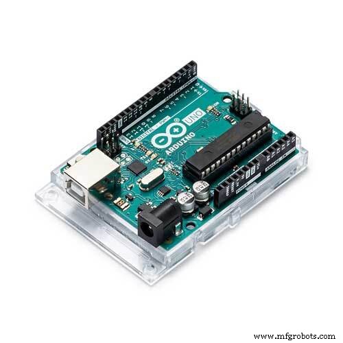
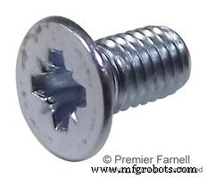
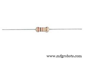
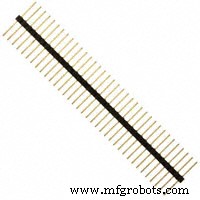
Components and supplies
 |
| × | 1 | |||
 |
| × | 1 | |||
 |
| × | 1 | |||
| × | 1 | ||||
 |
| × | 4 | |||
 |
| × | 3 | |||
| × | 4 | ||||
| × | 3 | ||||
 |
| × | 2 | |||
| × | 1 | ||||
| × | 6 | ||||
 |
| × | 1 |
Necessary tools and machines
 |
| |||
 |
| |||
 |
| |||
|
About this project
IntroductionMy girlfriend's TV remote control stopped working. She could have bought a cheap replacement at a store nearby, but then she thought: we are both engineers, let's make our own one together!
As we are quite complementary in our skills, this was a different, but fun way to spend some time during lockdown and it gave us the opportunity to learn a bit about how this everyday technology works.
Oh, and having a small 3D-printer at home also played a role.
How it worksFirst of all, as we wanted to make a simple design reliying on the Arduino UNO, we evaluated the minimum number of commands that we needed to operate our TV. We considered that 6 commands were enough: ON/OFF toggle, Source selection, Ch+, Ch-, Vol+, Vol-.
Button reading
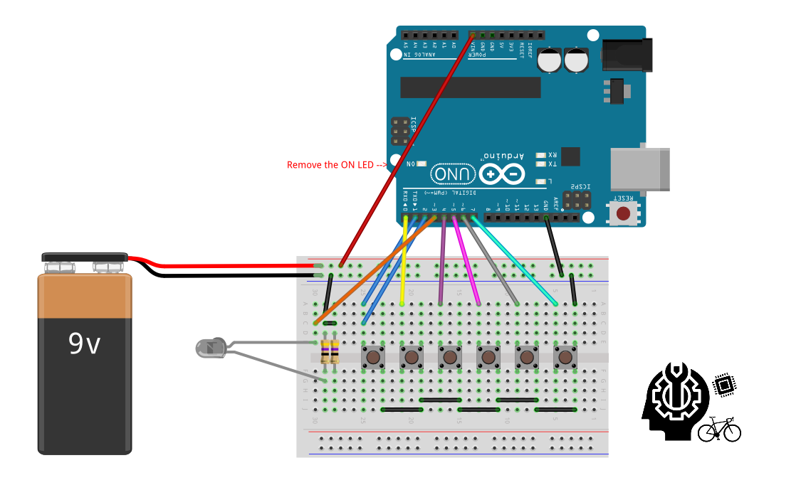
To avoid the use of additional resistors, the design relies on the internal pull-up resistors of the Arduino. If the remote control is not in sleep mode (see below), each button state is polled in each loop cycle. To avoid counting multiple hits, a simple debouncing routine is implememnted exploiting the millis() function.
Sending infrared signals
Infrared communication is dealt by the IRremote.h library (kudos to the coders!). All we had to do was to setup the protocol for our tv (different manufacturers have developed their own protocols) and search on Google for the codes in HEX of the different commands we wanted to use and associate them to the buttons. As it concerns the circuit design, to have the commands from the library effectively piloting the IR LED, this must be connected to pin3 of the Arduino UNO.
Currently, the code is written for three different types of tv, selectable by commenting/uncommenting a #define directive in the first part of code.
Battery saving
To reduce power consumption, a few strategies are implemented, exploiting the commands from the avr/sleep.h and avr/power.h libraries.
All the unused peripherals and interfaces (ADC, SPI, TWI, timer1, usart) are turned off in the setup routine. The built-in LED on PWM pin13 is also turned off. We also decided to desolder the power LED of the Arduino UNO, which otherwise is always on, although it's not a recommended operation.
Also, exploiting the millis(), if none of the button is pressed for 5 seconds the remote control enters a sleep mode, from which is woken up when the On/Off button is pressed again.
Electronics assembly
The whole circuitry is embedded on a prototyping board, designed to fit on the Arduino UNO headers. By using a soldering iron, the buttons were soldered considering the final position on the remote. On the bottom part, the two 47ohm resistors were soldered in parallel, in order to achieve the desired current through the IR LED.
Using the solder wire, traces were made on the prototyping board to connect the button pins and the IR LED to male pin headers.
In this way, the board resembles a shield which is fitted on the Arduino UNO using the pin headers, ensuring all the correct connections.
Enclosure CAD and CAM
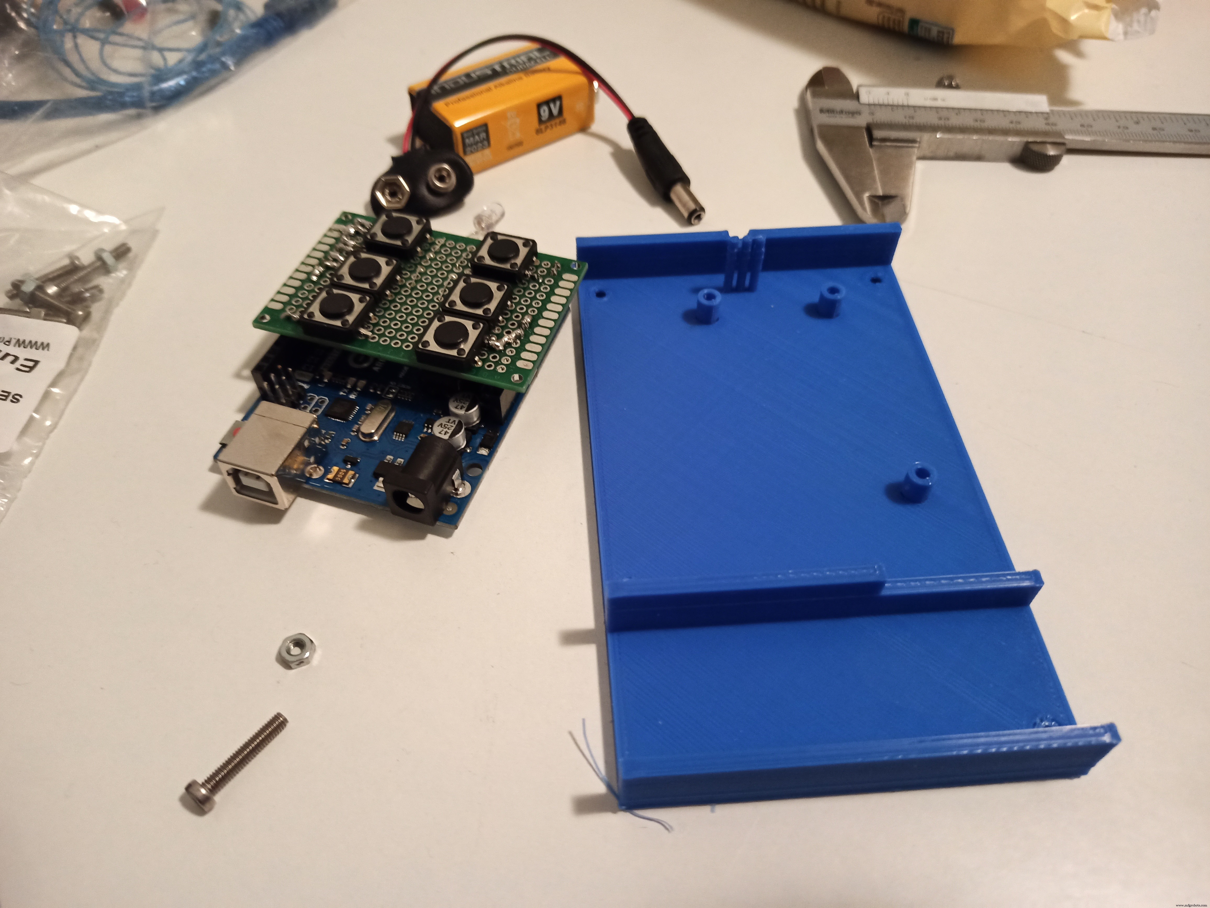
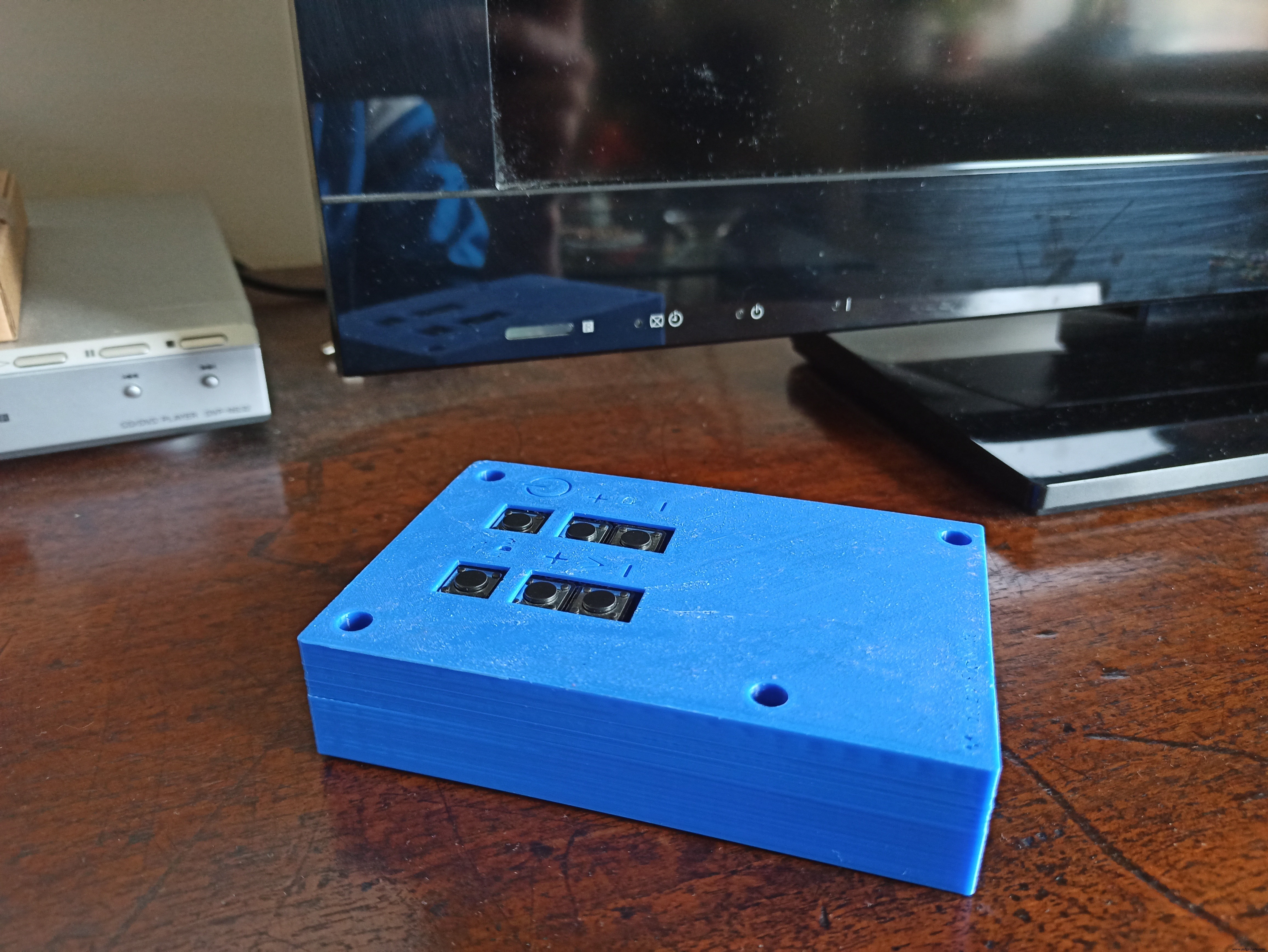
The enclosure was designed to contain the battery, the Arduino UNO + prototyping board assembly, exposing only the buttons on the top and the IR LED on the front side.
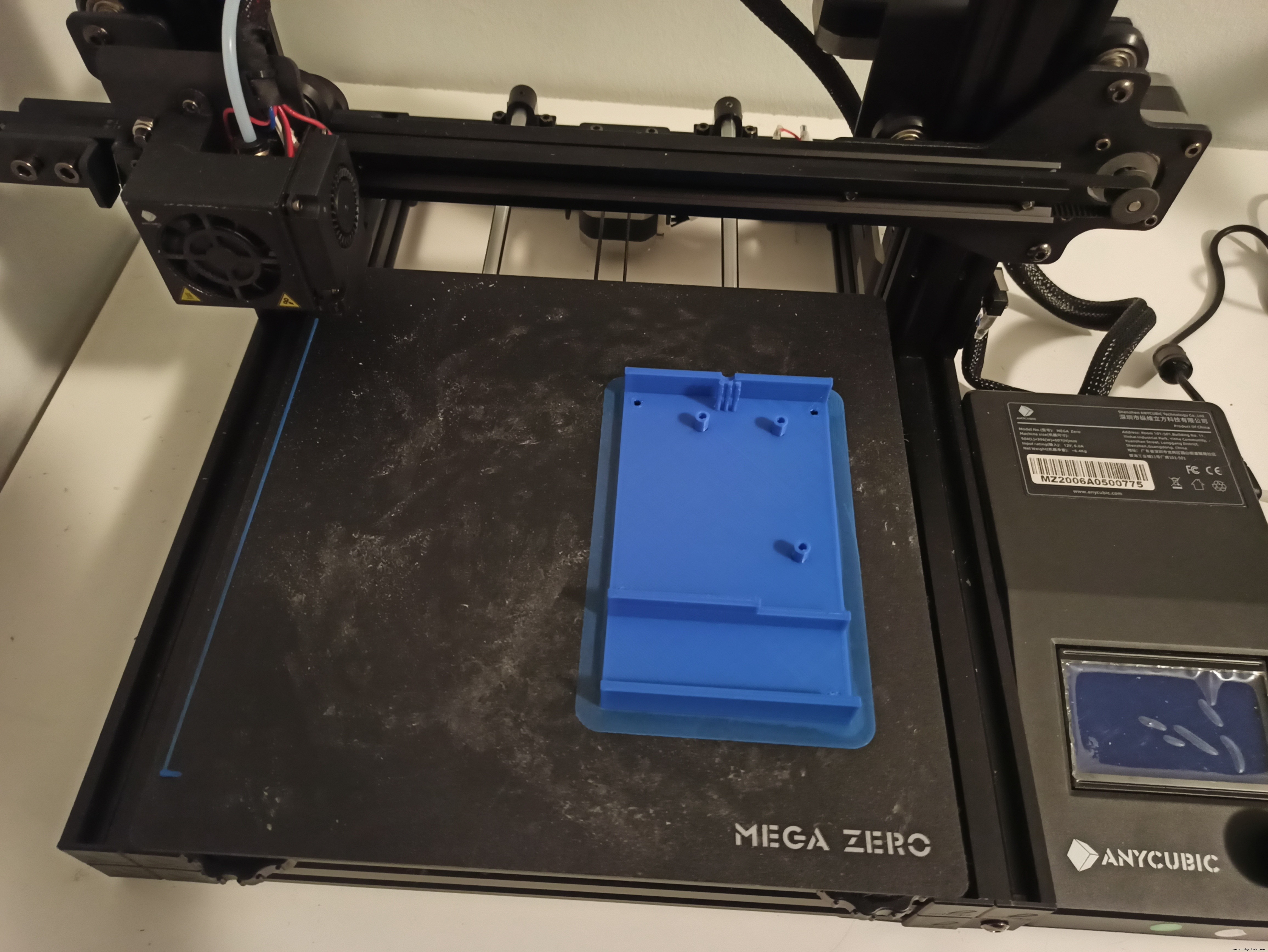
The enclosure consists of two parts, designed using SolidWorks CAD software, pre-processed with Ultimaker Cura slicing software and finally 3D printed in PLA using an Anycubic Mega Zero 3D-printer.
The Arduino UNO is secured to the base by using 3 M2.5 screws, which fit in alignment holes extruded from the inside of the base. Once the Arduino is secured, the IR LED will protrude outside the prototyping board, in order to align it with the purpose built-hole and to keep it in position while assembling the two parts of the enclosure, three mini-posts are added to avoid lateral movements of the LED leads. The battery is press-fitted into a dedicated space.
The cover is designed in order to expose only the buttons and besides each of them, a symbol is engraved in the cover to show the function of each button.
Base and cover of the enclosure are assembled using 4 M3 screws.
Photo gallery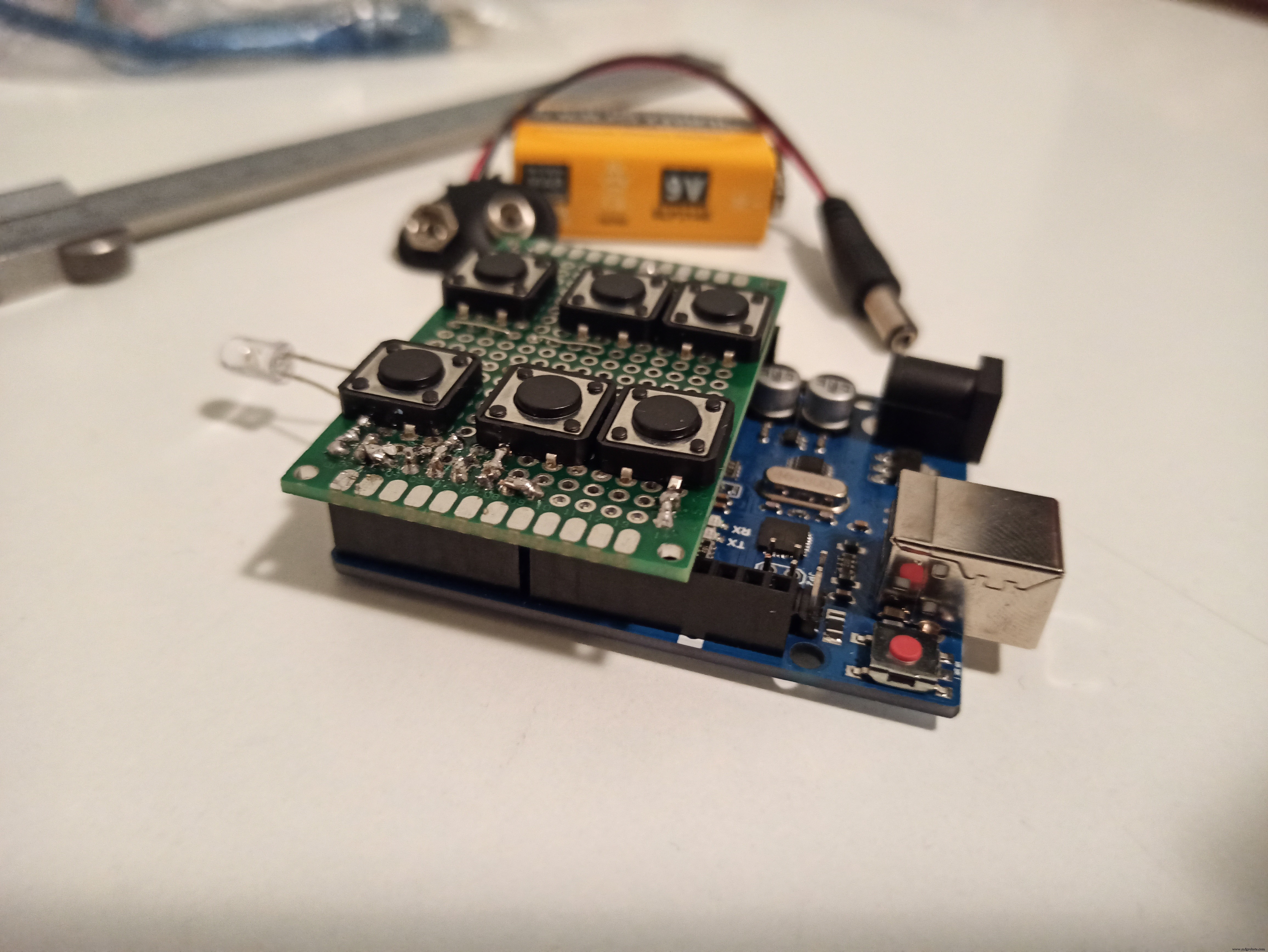
Code
- TV_remote.ino
TV_remote.inoArduino
#include <IRremote.h>
#include <avr/sleep.h>
#include <avr/power.h>
// Pin definition
// An IR LED must be connected to Arduino PWM pin 3
#define OnOff 1
#define Source 0
#define CH_plus 4
#define CH_minus 5
#define Vol_plus 6
#define Vol_minus 7
#define Interrupt_Pin 2 //Only pin 2 or 3 on Arduino Uno
// TV model definition
//#define LG_TV
//#define SAMSUNG_TV
#define SONY_TV
// Codes definition
#ifdef LG_TV
  unsigned long on_off_code = 551489775; // HEX 20DF10EF
  unsigned long vol_plus_code = 551502015; //HEX 20DF40BF
  unsigned long vol_minus_code = 551534655; //HEX 20DFC03F
  unsigned long ch_plus_code = 551485695; //HEX 20DF00FF
  unsigned long ch_minus_code = 551518335; //HEX 20DF807F
  unsigned long source_code = 551538735; //HEX 20DFD02F
#endif
#ifdef SAMSUNG_TV
  unsigned long on_off_code = 3772793023; // HEX E0E040BF
  unsigned long vol_plus_code = 3772833823; //HEX E0E0E01F
  unsigned long vol_minus_code = 3772829743; //HEX E0E0D02F
  unsigned long ch_plus_code = 3772795063; //HEX E0E048B7
  unsigned long ch_minus_code = 3772778743; //HEX E0E008F7
  unsigned long source_code = 3772809343; //HEX E0E0807F
#endif
#ifdef SONY_TV
  unsigned long on_off_code = 2704; //HEX A90
  unsigned long vol_plus_code = 1168; //HEX 490
  unsigned long vol_minus_code = 3216; //HEX C90
  unsigned long ch_plus_code = 144; //HEX 090
  unsigned long ch_minus_code = 2192; //HEX 890
  unsigned long source_code = 2640; //HEX A50
#endif
//Enable Debug
//#define DEBUG
//
IRsend irsend; //Create IR object
unsigned long debounce_time;
unsigned long last_time;

void setup() {
  analogWrite(13,0); //turn of builtin led
  //noInterrupts(); //disable interrupts
  //CLKPR = _BV(CLKPCE); //enable clock prescaler settings
  //CLKPR = _BV(CLKPS0); //set clock prescaler = 2 --> 8 MHz
  //interrupts();
  pinMode(OnOff,INPUT_PULLUP);
  pinMode(Source,INPUT_PULLUP);
  pinMode(CH_plus,INPUT_PULLUP);
  pinMode(CH_minus,INPUT_PULLUP);
  pinMode(Vol_plus,INPUT_PULLUP);
  pinMode(Vol_minus,INPUT_PULLUP);
  pinMode(Interrupt_Pin,INPUT_PULLUP);
  //power saving
  power_adc_disable(); //disable all ADCs
  power_spi_disable(); //disable SPI
  power_timer1_disable(); //disbale timer 1 (0 is for millis(), 2 is for irremote.h)
  power_usart0_disable(); //disable serial
  power_twi_disable(); //disable TWI
  #ifdef DEBUG
    Serial.begin(9600);
  #endif
}

void loop() {
 //check OnOff
 if (!digitalRead(OnOff)) {
  debounce_time = millis();
  while (millis() - debounce_time < 40 ) {
    ;
  }
  if (!digitalRead(OnOff)) {
    #ifdef LG_TV
      irsend.sendNEC(on_off_code, 32);
    #endif
    #ifdef SAMSUNG_TV
      irsend.sendSAMSUNG(on_off_code, 32);
    #endif
    #ifdef SONY_TV
      irsend.sendSony(on_off_code, 12);
    #endif
    last_time = millis(); //last time a button was pressed
    #ifdef DEBUG
      Serial.println("OnOff");
    #endif
  }
 }
 //check Source
 if (!digitalRead(Source)) {
  debounce_time = millis();
  while (millis() - debounce_time < 40 ) {
    ;
  }
  if (!digitalRead(Source)) {
    #ifdef LG_TV
      irsend.sendNEC(source_code, 32);
    #endif
    #ifdef SAMSUNG_TV
      irsend.sendSAMSUNG(source_code, 32);
    #endif
    #ifdef SONY_TV
      irsend.sendSony(source_code, 12);
    #endif
    last_time = millis(); //last time a button was pressed
    #ifdef DEBUG
      Serial.println("Source");
    #endif
  }
 }
 //check CH_plus
 if (!digitalRead(CH_plus)) {
  debounce_time = millis();
  while (millis() - debounce_time < 40 ) {
    ;
  }
  if (!digitalRead(CH_plus)) {
    #ifdef LG_TV
      irsend.sendNEC(ch_plus_code, 32);
    #endif
    #ifdef SAMSUNG_TV
      irsend.sendSAMSUNG(ch_plus_code, 32);
    #endif
    #ifdef SONY_TV
      irsend.sendSony(ch_plus_code, 12);
    #endif
    last_time = millis(); //last time a button was pressed
    #ifdef DEBUG
      Serial.println("CH+");
    #endif
  }
 }
 //check CH_minus
 if (!digitalRead(CH_minus)) {
  debounce_time = millis();
  while (millis() - debounce_time < 40 ) {
    ;
  }
  if (!digitalRead(CH_minus)) {
    #ifdef LG_TV
      irsend.sendNEC(ch_minus_code, 32);
    #endif
    #ifdef SAMSUNG_TV
      irsend.sendSAMSUNG(ch_minus_code, 32);
    #endif
    #ifdef SONY_TV
      irsend.sendSony(ch_minus_code, 12);
    #endif
    last_time = millis(); //last time a button was pressed
    #ifdef DEBUG
      Serial.println("CH-");
    #endif
  }
 }
 //check Vol_plus
 if (!digitalRead(Vol_plus)) {
  debounce_time = millis();
  while (millis() - debounce_time < 40 ) {
    ;
  }
  if (!digitalRead(Vol_plus)) {
    #ifdef LG_TV
      irsend.sendNEC(vol_plus_code, 32);
    #endif
    #ifdef SAMSUNG_TV
      irsend.sendSAMSUNG(vol_plus_code, 32);
    #endif
    #ifdef SONY_TV
      irsend.sendSony(vol_plus_code, 12);
    #endif
    last_time = millis(); //last time a button was pressed
    #ifdef DEBUG
      Serial.println("Vol+");
    #endif
  }
 }
 //check Vol_minus
 if (!digitalRead(Vol_minus)) {
  debounce_time = millis();
  while (millis() - debounce_time < 40 ) {
    ;
  }
  if (!digitalRead(Vol_minus)) {
    #ifdef LG_TV
      irsend.sendNEC(vol_minus_code, 32);
    #endif
    #ifdef SAMSUNG_TV
      irsend.sendSAMSUNG(vol_minus_code, 32);
    #endif
    #ifdef SONY_TV
      irsend.sendSony(vol_minus_code, 12);
    #endif
    last_time = millis(); //last time a button was pressed
    #ifdef DEBUG
      Serial.println("Vol-");
    #endif
  }
 }
 if (millis()-last_time > 5000) { //a button has not been pressed for 10 s
  #ifdef DEBUG
      Serial.println("Going to sleep...");
  #endif
  going_to_sleep(); //enter sleep mode
  #ifdef DEBUG
      Serial.println("Waking up...");
  #endif
 }
}

//Sleep Mode function
void going_to_sleep() {
  sleep_enable(); //enable sleep mode
  attachInterrupt(digitalPinToInterrupt(Interrupt_Pin), wake_up, LOW); //interrupt for waking up --> configure Interrupt Pin as a WIRED NOR!!!
  set_sleep_mode(SLEEP_MODE_PWR_DOWN); //full sleep mode
  sleep_cpu(); //activate sleep mode
}

//Wake Up function
void wake_up() {
  sleep_disable(); //disable sleep mode
  detachInterrupt(digitalPinToInterrupt(Interrupt_Pin)); //remove the interrupt
}
Custom parts and enclosures
Schematics
 remote_sketch_r4f8a47oWX.fz
Manufacturing process
- PiCy: Build Your Own Tiny Raspberry Pi‑Powered Robot
- Build a Smart Piggy Bank: Control a Coin Acceptor with Arduino Nano
- Control an LED via Bluetooth with Arduino – Simple DIY Guide
- Build a Functional Arduino-Powered 3D‑Printed Robotic Arm – Step‑by‑Step Guide
- DIY Arduino Humidifier Controller with Relay – Safe High‑Voltage Setup
- Control an Arduino LED with Cortana via Bluetooth on Windows 10
- Build a 4WD IR Remote‑Controlled Arduino Robot Car Kit
- Control Music Playback with Your Remote: A Simple Arduino Project
- Control Any Device with Your TV Remote Using Arduino IR – Step-by-Step Tutorial
- Mitsubishi Electric Launches CNC Offset Manager: Remote CNC Offset Control for Enhanced Efficiency