


Smart Temperature Monitoring System for Schools: Accurate, Real‑Time, and Secure
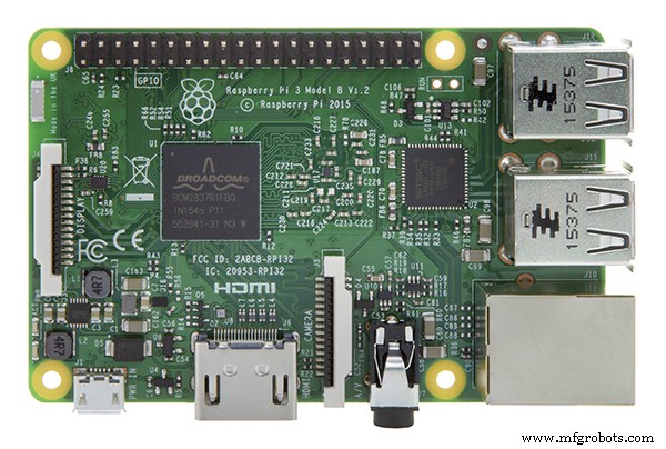
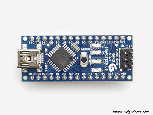
Components and supplies
 |
| × | 1 | |||
 |
| × | 1 | |||
 |
| × | 1 | |||
 |
| × | 1 | |||
| × | 1 | ||||
| × | 1 | ||||
| × | 1 | ||||
 |
| × | 1 | |||
 |
| × | 1 | |||
 |
| × | 2 | |||
 |
| × | 1 |
Apps and online services
 |
| |||
| ||||
 |
| |||
| ||||
| ||||
|
About this project
PROBLEM STATEMENT
In Asia, due to hot weather and the outbreak of severe acute respiratory syndrome (SARS) in 2003, the primary and secondary school students need to perform temperature measurement during every quarter to ensure the well being of the students. Whenever there is a temperature taking exercise scheduled by the school, students are required to bring their own digital thermometer for this exercise. However, some students might not be able to participate during the exercise due to the reasons like misplaced or damaged thermometer and forget to bring the device. Due to personal hygiene, students are not allow to share their thermometers and they might not have sufficient money to buy a new piece. Hence, it affects the success rate of the temperature taking exercise. After the temperature measurement exercise, staff will have to manually key all the students temperature data and students particular to database. The task is very tedious and time consuming as each form teacher will need to perform entries for about 40 students.
What's The Solution?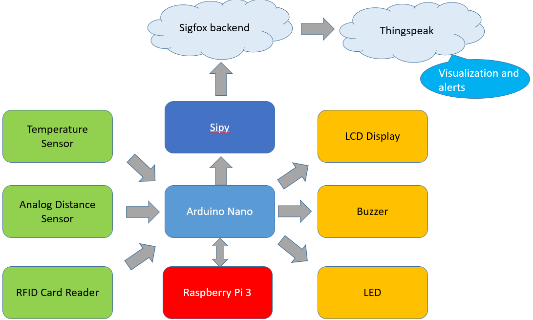
The Theme for our project is Social Impact by SqwidNet, and in the area of Good health and well-being in the Sustainable Development Goal (SDG). The reason for it is because our system is able to deploy to automatically measure the temperature of valid users so that their temperature can be monitored and an alert will be sent whenever it exceeds a certain threshold level.
HOW IT WORKS: RaspberryPi & ArduinoThe RaspberryPi holds a Python Program & the MySQL database.
Upon launching the Python Program, it automatically checks for if the database if already created, if not, it'll be created automatically. The tables inside will also be checked & created automatically if needed. This reduces the manual labor work of teachers/administrative staffs in the school.
Then, it establishes a query connection to check the database and awaits for the Arduino to send relevant information through the Serial Communication port.
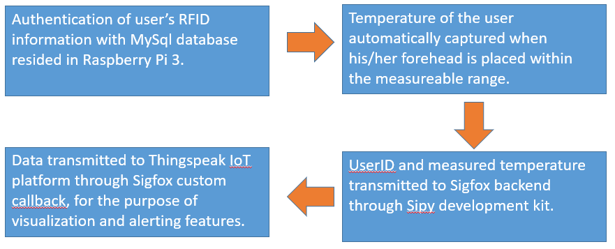
Upon having an RFID card tap on the Arduino, the card information is stored in the Arduino, sent to the RaspberryPi via Serial Communication. Afterwards, RaspberryPi confirms with the database that said card is a valid user, and if it is, it sends to the Arduino confirming it and the Arduino outputs "Welcome, name" on the LCD screen. If it's not a valid user, it'd just say "Error! Invalid User!".
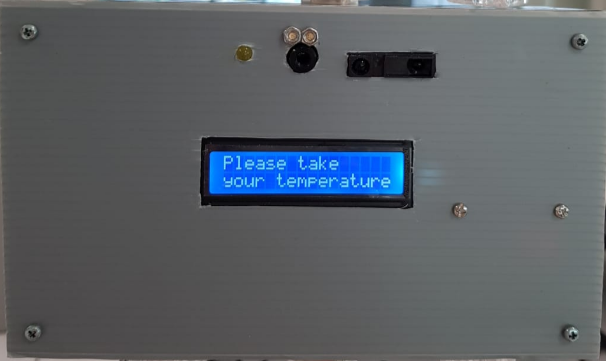
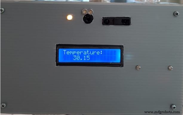
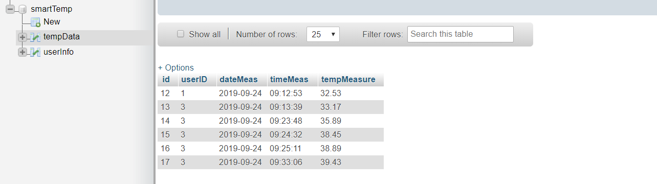
Let's say, now, we have a valid user that just tapped. Next, the Arduino will prompt the user to take their temperature. A distance sensor will then sense if a user is ready to take their temperature. If they are, it'll take their temperature and output their temperature on the LCD screen. If it's a valid temperature (28*C - 42*C), this information will be sent both to the RaspberryPi (MySQL) and Sigfox (ThingSpeak) for data storing. The MySQL database would store the userID, date, timestamp and the temperature of each taking.
When receiving the temperature data from the Arduino, the RaspberryPi would constantly check if the temperature is properly delivered before proceeding with anything else. This is because, if the Python Program only checks once for the temperature data, it might not have been sent yet by the Arduino, because both of the code executes at different timing. So to sync, we constantly check for the temperature data on the Python code before proceeding with the rest of the program.
NOTE: Both the RaspberryPi's Python code & Arduino code utilizes a syncing method called Handshaking. If the RaspberryPi is not ready to receive another temperature/user information, the Arduino would not allow the user to tap the card, vice versa.
A simple way I did that is to constantly send a "READY" signal till the other party sends back a "RECEIVE" signal so they know that they are both ready.
Arduino -
boolean readySignal = Serial.readString() == "READY";


if(readySignal)
{

tapped = true;

Serial.println("RECEIVED");

}
Python -
while(readySignal == True):

ser.write(b'' + "READY")


receivedSignal = ser.readline().strip() == "RECEIVED"


if(receivedSignal == True):

readySignal = False
Remember to close your query connection every-time you're done with a query! This is to eliminate any possible memory leak and it's a good practice overall.
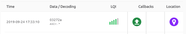
HOW IT WORKS: Sigfox (SiPy)After receiving the temperature data from the Arduino, the SiPy will separate the userID, and the temperature into whole numbers and decimal places. After doing this, all the data is sent to the Sigfox backend through bytes (so that it can be sent to Ubidots as well as ThingSpeak)and should look something like the following picture.
After receiving this, the Sigfox backend will re-code this data to be sent to ThingSpeak to be stored. The following will show you how to code the backend for sending data to thingspeak.
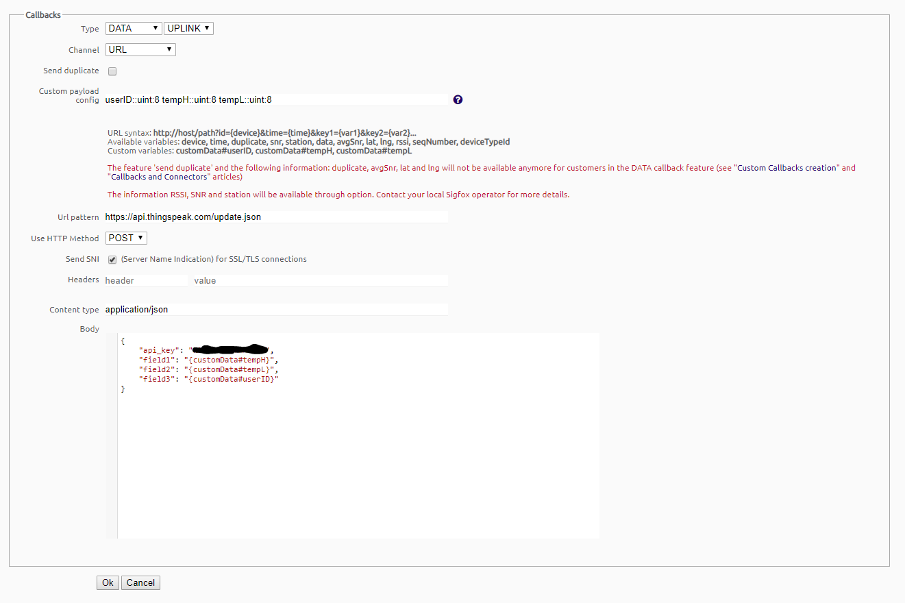
In the Sigfox Backend under device type > Device Name > CALLBACKS, you will need to put in the custom payload exactly as itis unless you have changed the coding in the SiPy as the custom pay load will set what is received first as the userID, so for example if you send up the temperature first, on the backend it will convert that temperature to the userID instead of temperature. In the body, the write api key needs to go on top, while the fields can be placed with any of the custom data you have created in the custom payload.
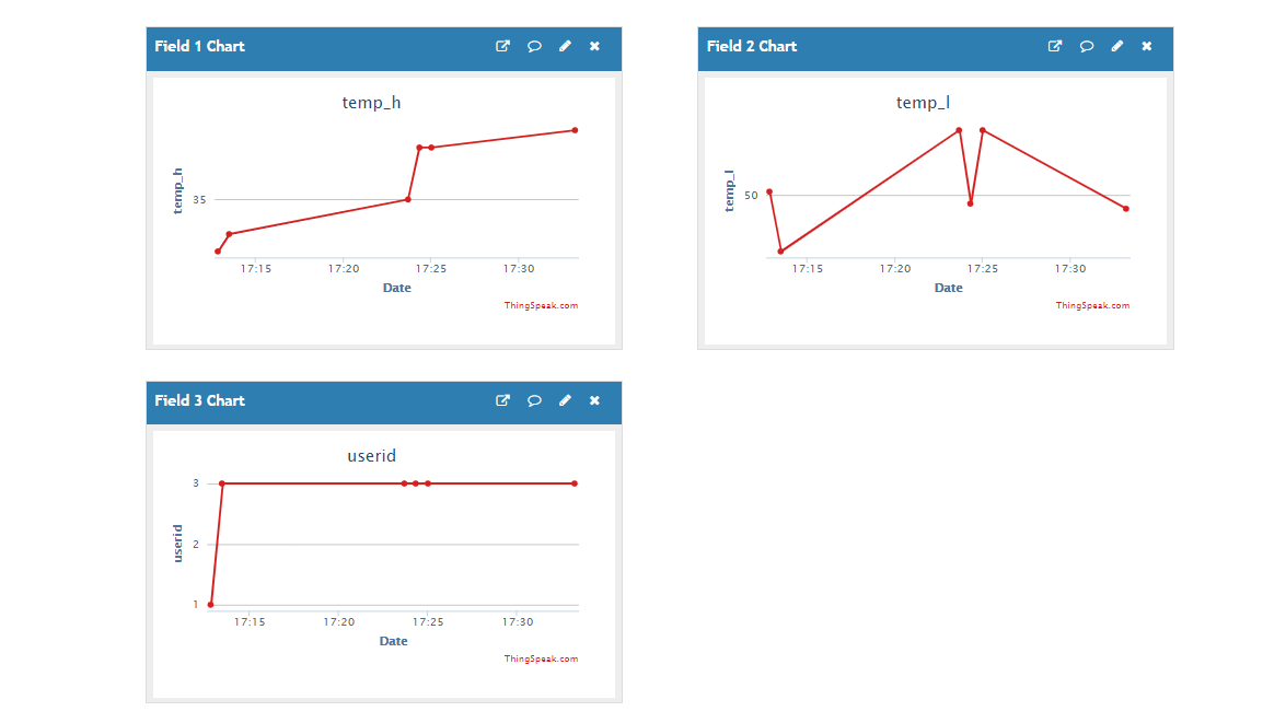
After the data is successfully sent up to ThingSpeak, it first receives it in a private viewing channel where a MATLAB Analysis script analyses the data and combines the temperature data into one value instead of the separation of a whole number value & a decimal value.
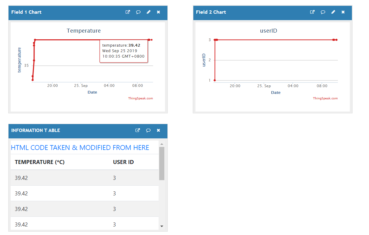
The table code was taken from an open sourced project and modified to suit our needs. It's very useful as the table auto updates every time a new data is sent in, perfect for our usage.
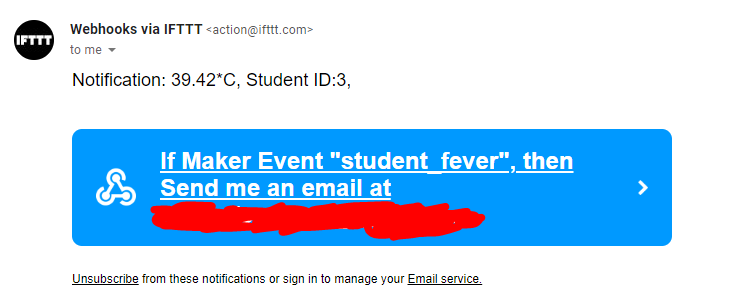
At the same time, it checks if the temperature is at a dangerous level (fever), if so, an email will be sent to notify the staffs/teachers.
In summary, the first channel that has the temperature value separated in whole number & decimal number is a backend channel, not really for viewing. For the second channel, the temperature values have been combined and made nice for staffs/management/administrators to view and has an Excel-like table for easy data analysis.
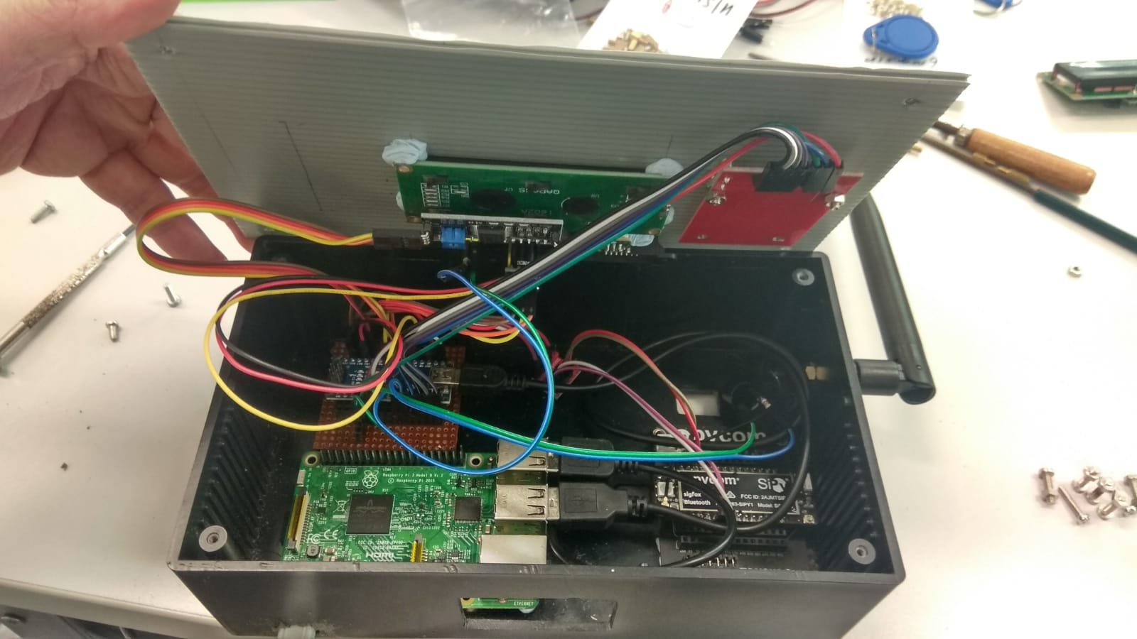
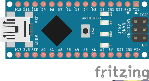
1. Arduino Nano Connections SetupFor the Arduino Nano, here are the connections we have made with our modules.
Nano and Uno have the same Pinout.
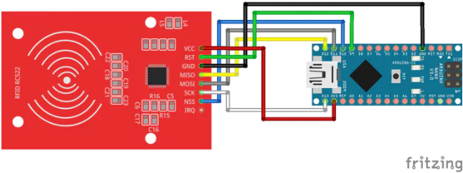
RFID - RC522

SDA    D10
SCK    D13
MOSI   D11
MISO   D12
IRQ    UNCONNECTED
GND    GND
RST    D9
3.3V   3.3V
How to test RFID
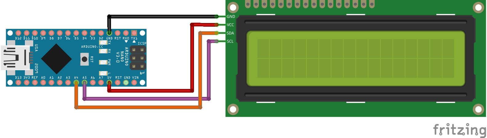
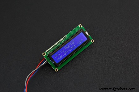
LCD

SDA    A4
SCL    A5
GND    GND
5V     5V
How to test I2C LCD
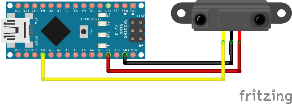
Distance Sensor

5V    5V
GND   GND
Input A0
How to test Sharp IR Distance Sensor
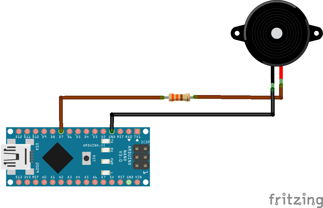
Buzzer

GND    GND
Output D6
How to test Buzzer
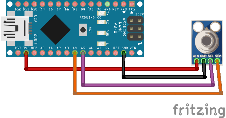
IR Temperature Sensor

SDA    A4
SCL    A5
GND    GND
5V     5V
How to test the IR Temperature Sensor,
LED

Flat Side(cathode)     GND
Non-flat Side(Anode)   D7
Good! For the Arduino connections, you should be good to go now.
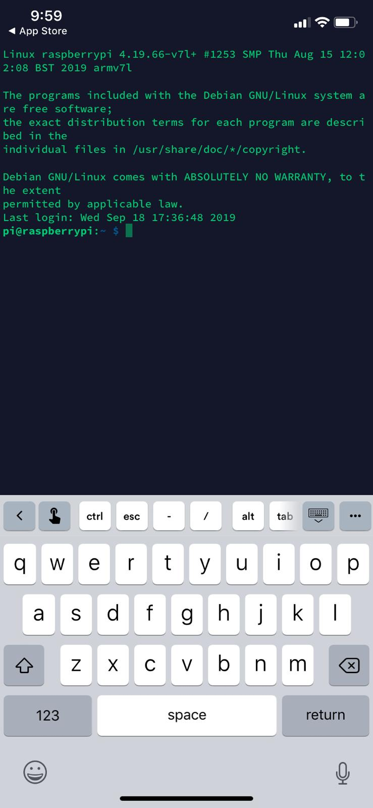
2. RaspberryPi SetupThere are mainly two things that needs to be installed onto your Raspberry Pi 3 machine,
1. Raspbian OperatingSystem-
The installation of the Raspbian Operating System is considered fairly straight forward.
A short answer on how to do it would be flashing (writing) an image file onto a SD card and slot this SD card into the Raspberry Pi 3.
However, if you're looking for a step by step long answer tutorial, here's how to do it -
Firstly, you have to download a software that allows you to flash.img files into a storage drive. You can use the software called balenaEtcher.
Afterwards, head to the Raspberry Pi - Raspbian page and pick a one that suits your need. I chose the "Raspbian Buster with Desktop and recommended software" because like the name says, it comes with recommended software and that saves you the extra hassle of downloading softwares.
Once you're done with the aforementioned steps, simply launch the balenaEtcher software. This step is pretty self explanatory: Select the image (your.img Raspbian file), then select your SD card, and press flash. Now, you just have to wait. Once it's done, it should prompt you and you can now insert the newly flashed SD card into your Raspberry Pi.

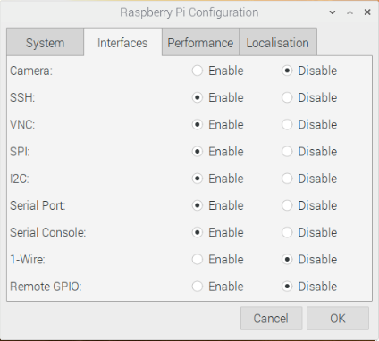
Following this, connect your Raspberry Pi machine via HDMI to a monitor and do your initial setup. Lastly, head to Preferences -> Raspberry Pi Configuration and you should be on this menu -
Follow the options, this step enables interfaces like SSH, VNC that allows you to connect to ip addresses via eth0 or wlan0 (So you don't need the HDMI cable anymore, you can do it all via SSH).
(optional step) - I open the terminal and edit the dhcpcd.conf file (sudo nano /etc/dhcpcd.conf) and I add these command lines,
interface eth0
static ip_address=192.168.0.11/24
The above allows me to connect to the Raspberry Pi via an Ethernet Cable with the static address, 192.168.0.11, so I know every single time that, that is my Raspberry Pi's address.
This is an option step as, once you're connected to WiFi, you will gain a wlan0 ip address that allows you to connect to the Raspberry Pi without an Ethernet Cable and anywhere in the location as long as you're connected to the same WiFi. To see what's your wlan0 IP ADDRESS, simply hover your mouse over the WiFI symbol located at the top right and it'll indicate.
Nice! You're done with your initial Raspberry Pi's setup!
3. MySQL Database SetupI would consider this step a little difficult, especially the part where you have to setup the MySQL root user, follow it carefully because it's very difficult to rectify any errors.
First, you have to make sure your system is upgraded and updated to the latest firmware. You can make sure by entering these commands,
sudo apt update
sudo apt upgrade
After this is done, you will install apache2.
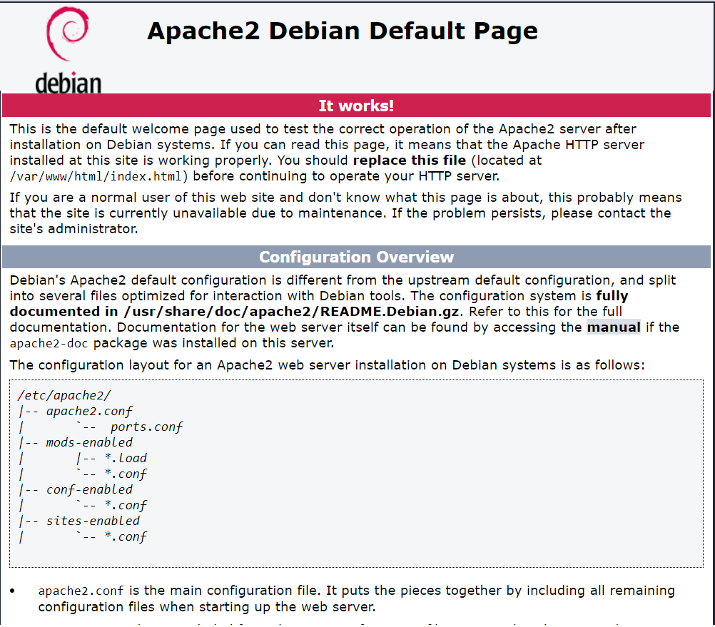
sudo apt install apache2Apache2 will allow you to create a web server so you can access the websites you create later.
Once apache2 is installed, you need to install PHP.
sudo apt install php php-mbstringPHP will allow you to create and see your own PHP websites.
Let's stop and see if everything you just installed is working, simply type your Raspberry Pi's IP in your web browser or "localhost" if you're still connected via HDMI, and you should see an Apache index page.
Now, you will need to install the database. For this, you will be using MySQL and mariadb.
sudo apt install mariadb-server php-mysqlIMPORTANT - Please make sure you read what's below very carefully.
Now, you will create your MySQL root user so you can use it to access the database.
sudo mysql --user=rootYou will now enter a MySQL session where you can type MySQL codes, type these line by line, (You can replace password with your own password)
DROP USER 'root'@'localhost';
CREATE USER 'root'@'localhost' IDENTIFIED BY 'password';
GRANT ALL PRIVILEGES ON *.* TO 'root'@'localhost' WITH GRANT OPTION;
FLUSH PRIVILEGES;
exit;
You can now test your MySQL root user by logging in;
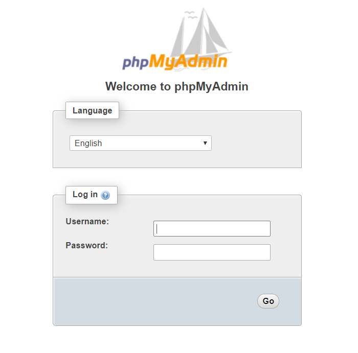
mysql --user=root --password=yourmysqlpasswordIf it all works, now you can install PHPMyAdmin, the Administrator Control Panel for you to access (view) and modify the MySQL database.
sudo apt install phpmyadmin

(after installation)
sudo phpenmod mysqli
sudo /etc/init.d/apache2 restart
Congratulations! You can now access your newly made database using http://your_raspberrypi_ip_address/phpmyadmin.
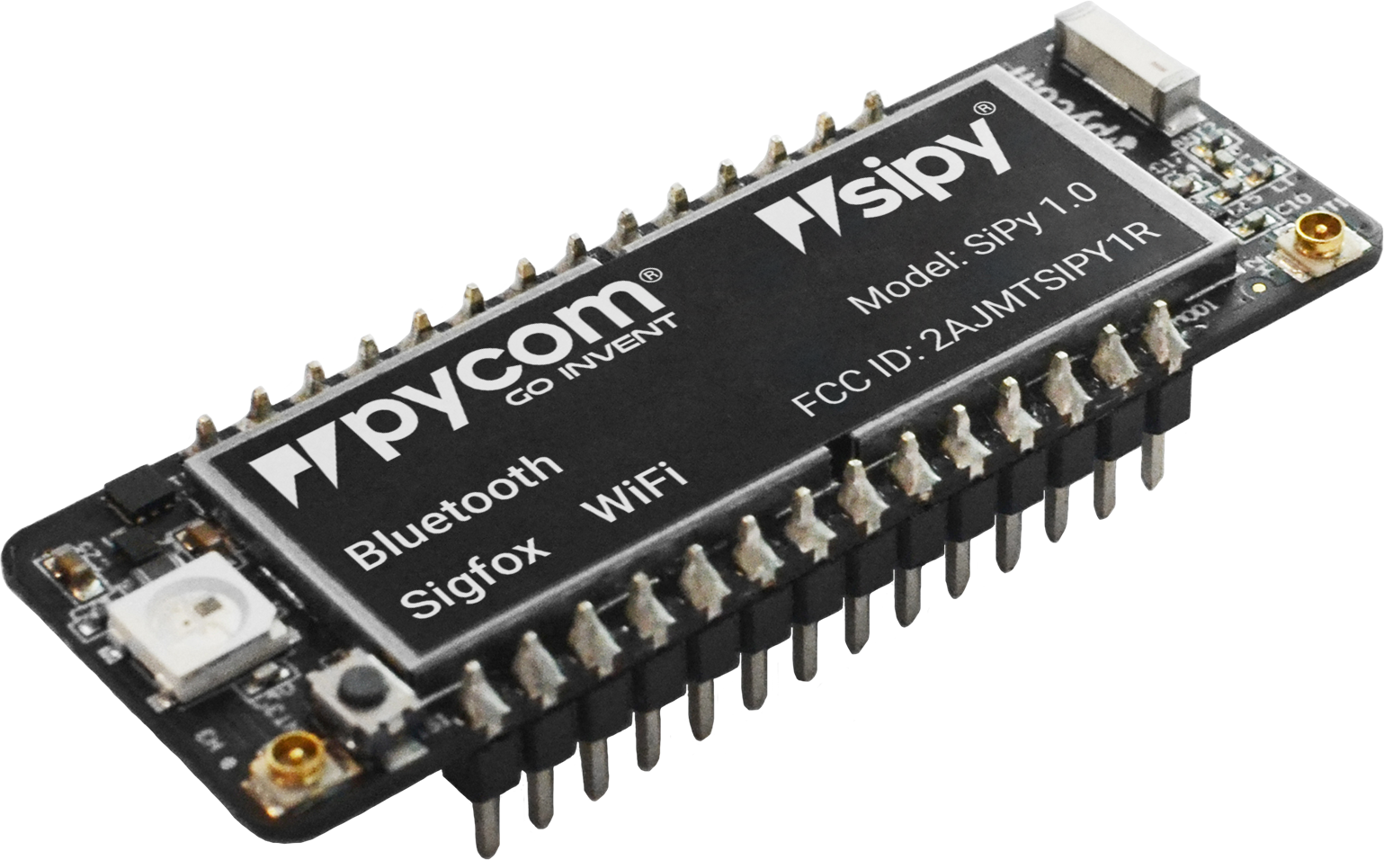
Firstly, you will need to insert the SiPy Module onto the Expansion Board with the reset button facing the USB Connector and should firmly click into place with the pins no longer visible.
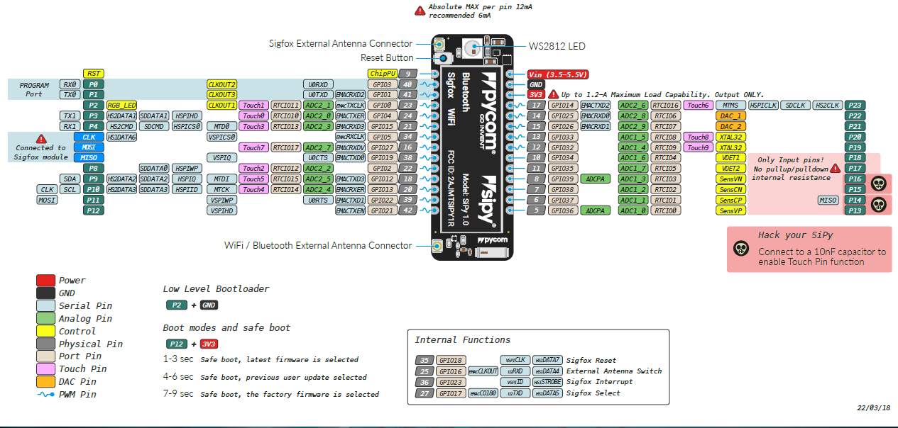
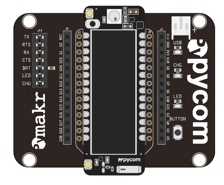
Source: Pycom Documentation
After doing that, you will need to update the firmware on the SiPy, so that you can upload and run programs as well as getting the Sigfox Device ID and PAC number which will be used to register for the Sigfox backend. Download the firmware updater according to what OS(operating system) you are using.
- Windows
- macOS (10.11 or Higher)
- Linux (requires
dialogandpython-serialpackage)
After downloading the pycom firmware upgrade, when you start the updater for the first time, the following pictures will only occur once so ensure you select the correct Sigfox Region, Board.
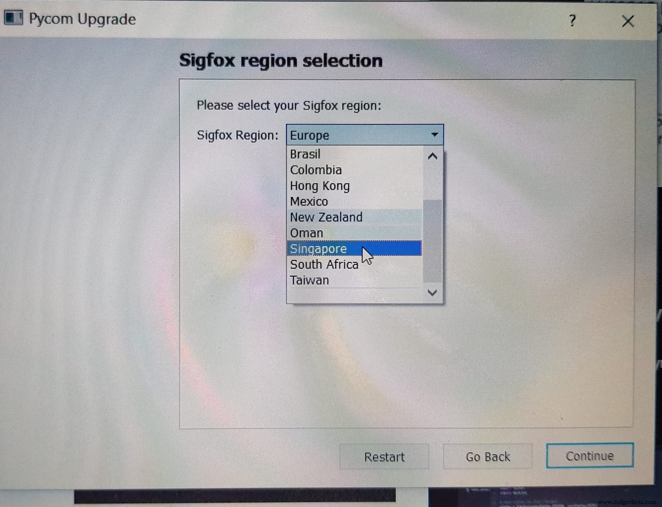
Follow the instructions on the firmware update carefully as it can cause your Sigfox to not function properly like the Sigfox Device ID and PAC number being all "F" (like below) instead a mixture between numbers and alphabets.
b 'FFFFFFFF'
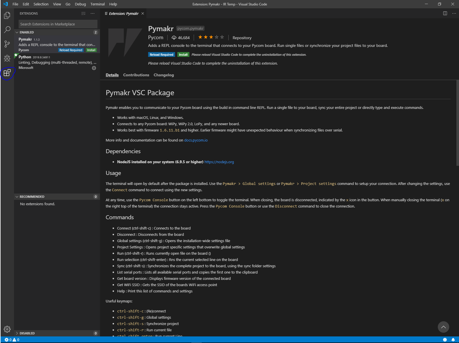
b 'FFFFFFFFFFFFFFFF'Once the firmware has been updated, you will need to download Visual Studio Code and install the extension Pymkr as well as nodejs before you can start uploading and running programs on the SiPy.
Firstly, you will need to create a new folder to save all the files you are going to upload into the SiPy later on or just to store all the programs you are going to run. Press file at the top left corner and press Open Folder or Ctrl+K+O, then select where you want to put this folder and right click to create a new folder. After that, create a new file or Ctrl+N to open a new file. After creating a new file, you will need to save the new file as a python and change the save as type to python file so that the code can be run on the SiPy later on and save it into the new folder you created.
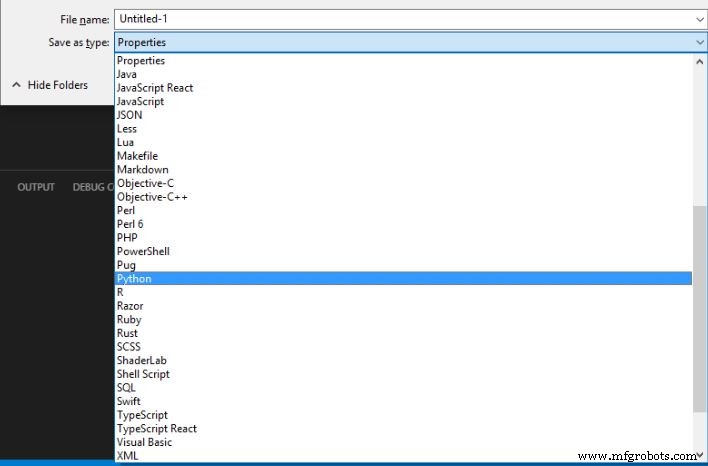
Note: File Name can be anything like Test, Trial, Etc.. But if uploading into the SiPy file name need to be called main.
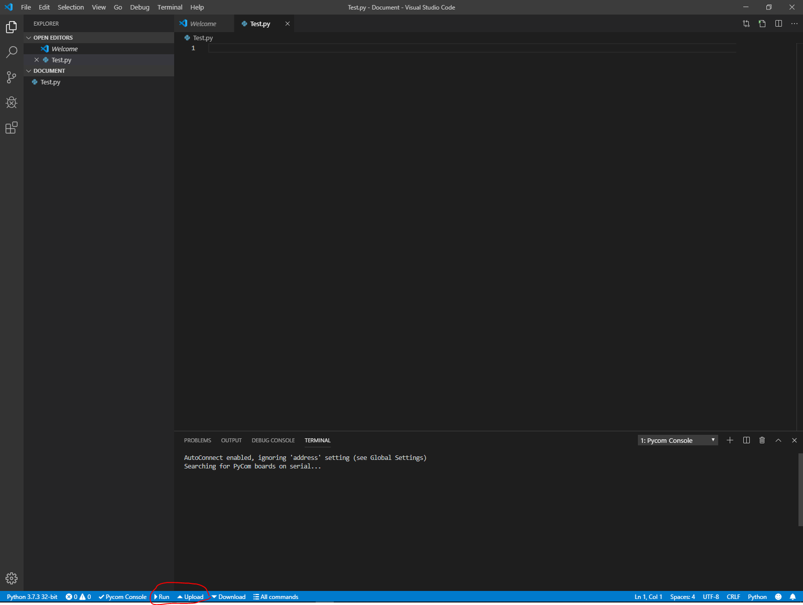
To just run your code without uploading it into the Sipy Module all you have to do is press the run button located at the bottom of the program. The upload next to it uploads the current folder to the SiPy Module. Be careful when using while 1 loops as once these are uploaded into the SiPy Module, the only way to access the SiPy Module again is to FTP into the flash and remove the main.py file from the SiPyModule.
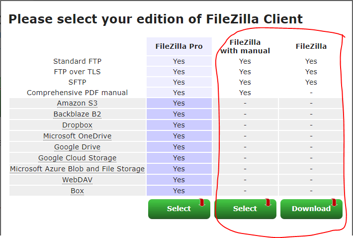
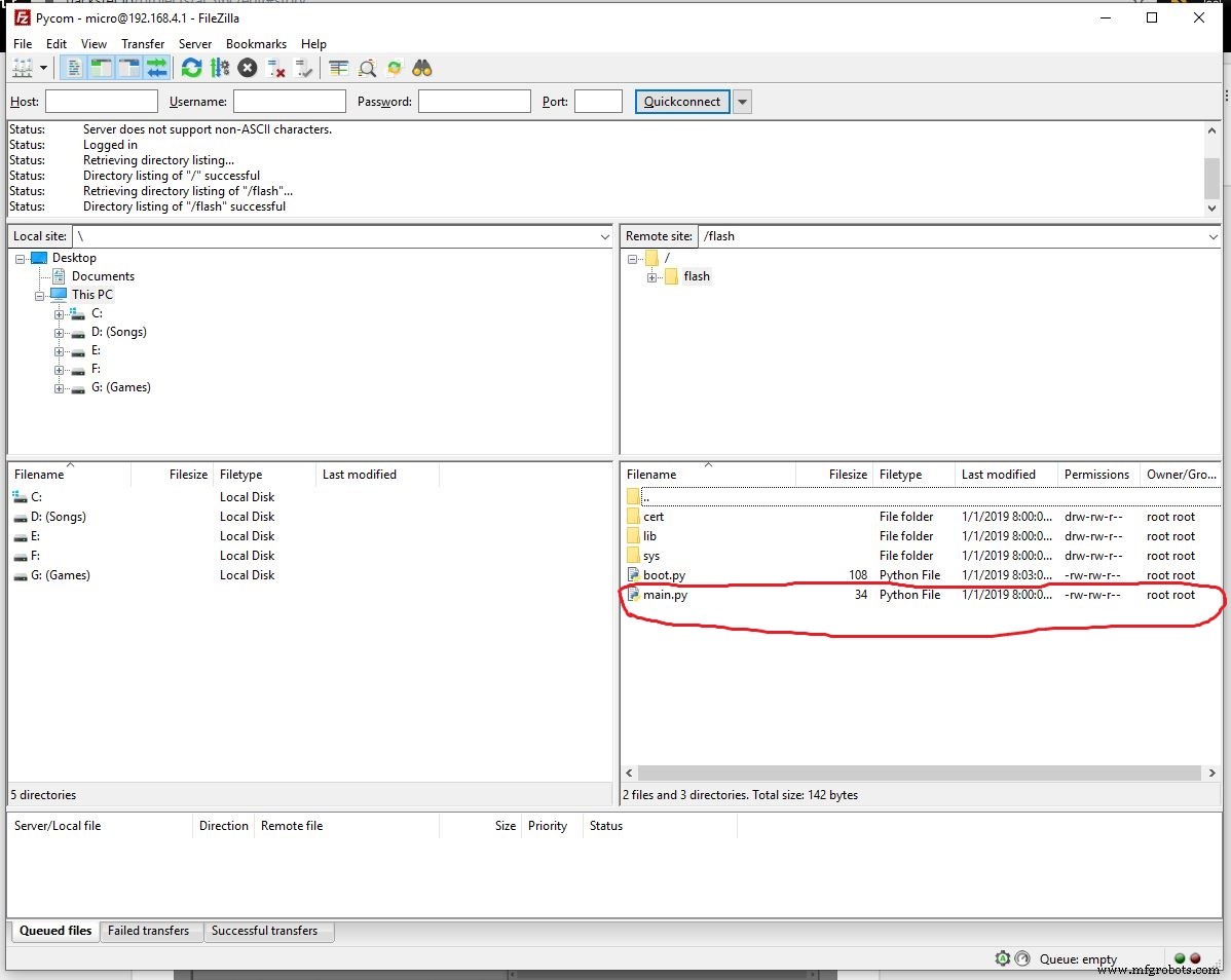
If you accidentally added a infinite while loop, there's no need to worry as you can still upload your program or remove the previous one through FTP. Firstly, go and download filezilla free version and install it.
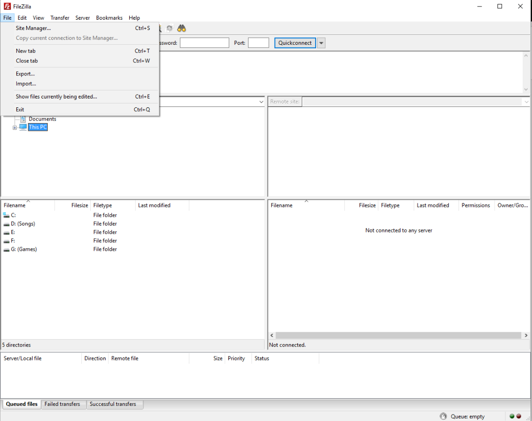
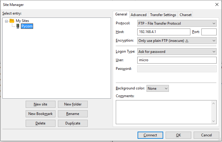
After installing, you will need to setup the connection. Firstly open up filezilla and go to site manager which is under file or press Ctrl+S and press new site.
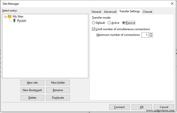
You can rename the site to SiPy or whatever you want to call this connection and change the settings for encryption to Only use plain FTP (insecure) and transfer settings to passive and limit the number of active connections to 1
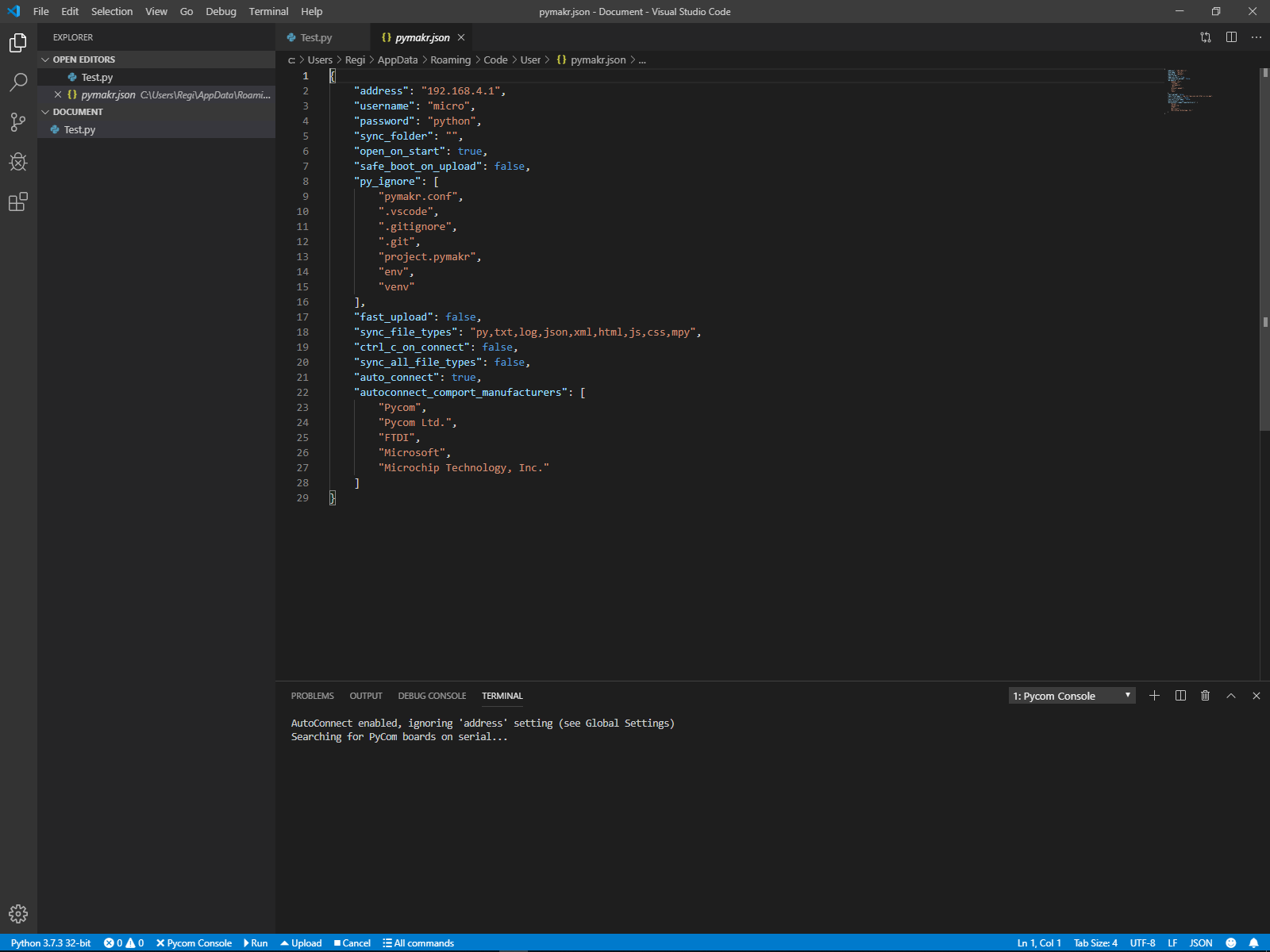
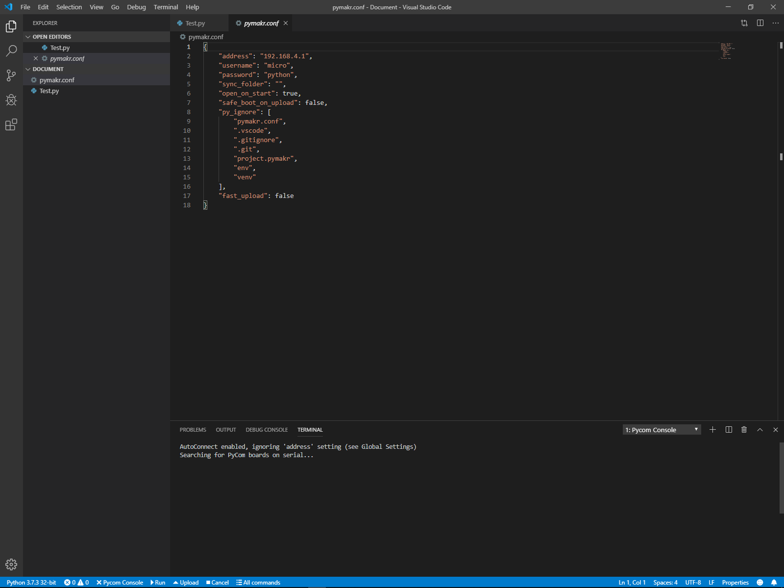
You can find the Host (address), User and Password through Visual Studio Code by pressing all commands and selecting global setting. This will show you the default settings for the Host (address), User (username) and password. This can be changed by pressing the project settings in all commands.
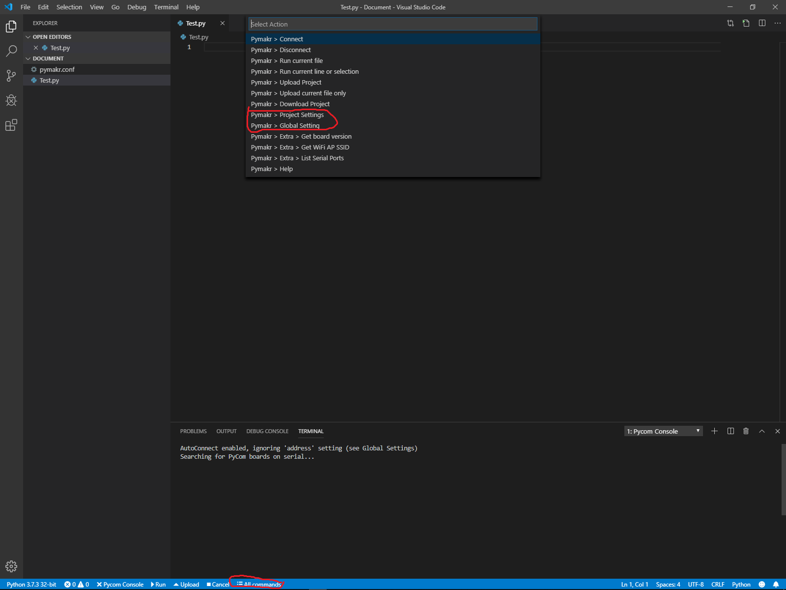
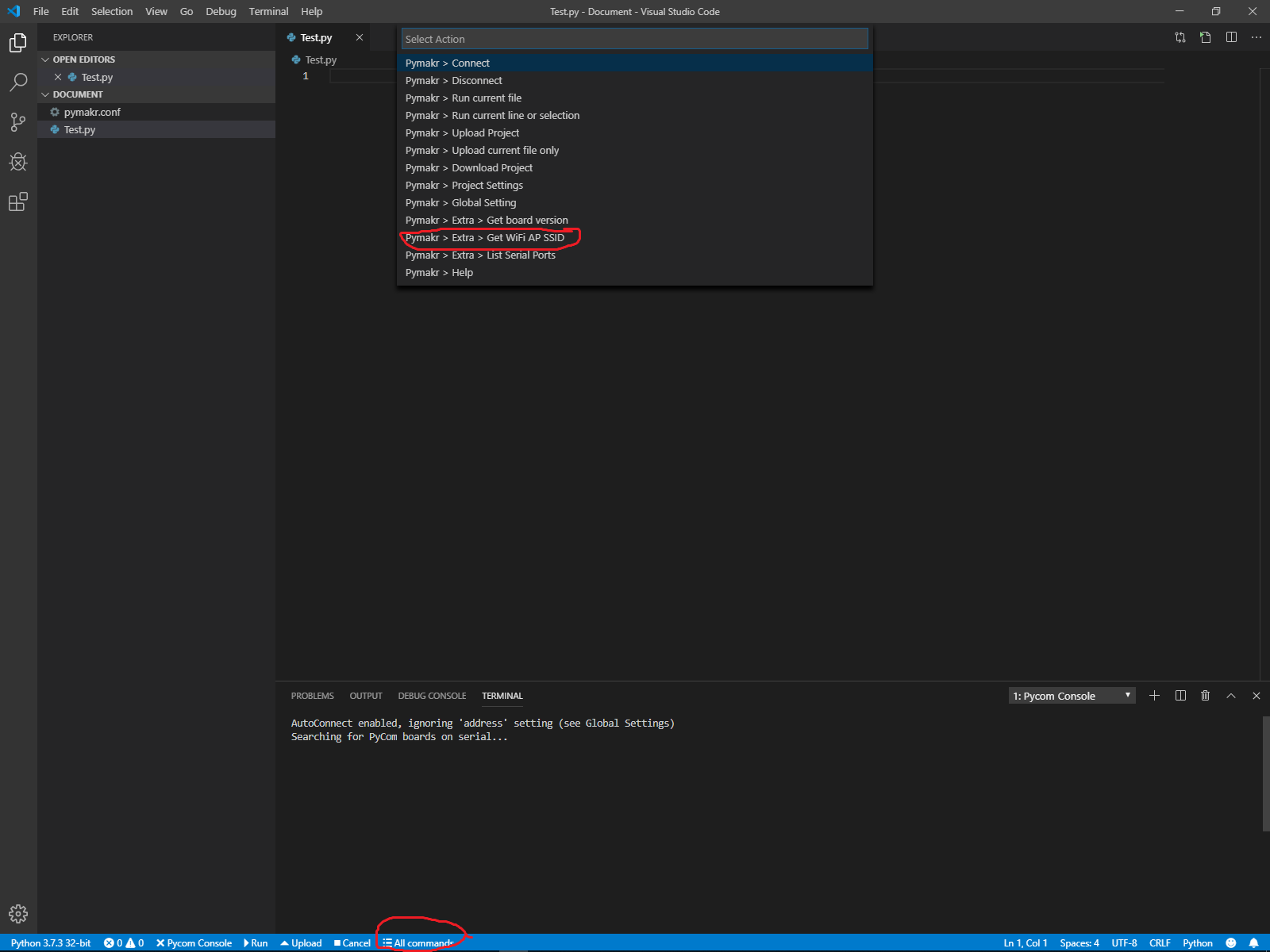
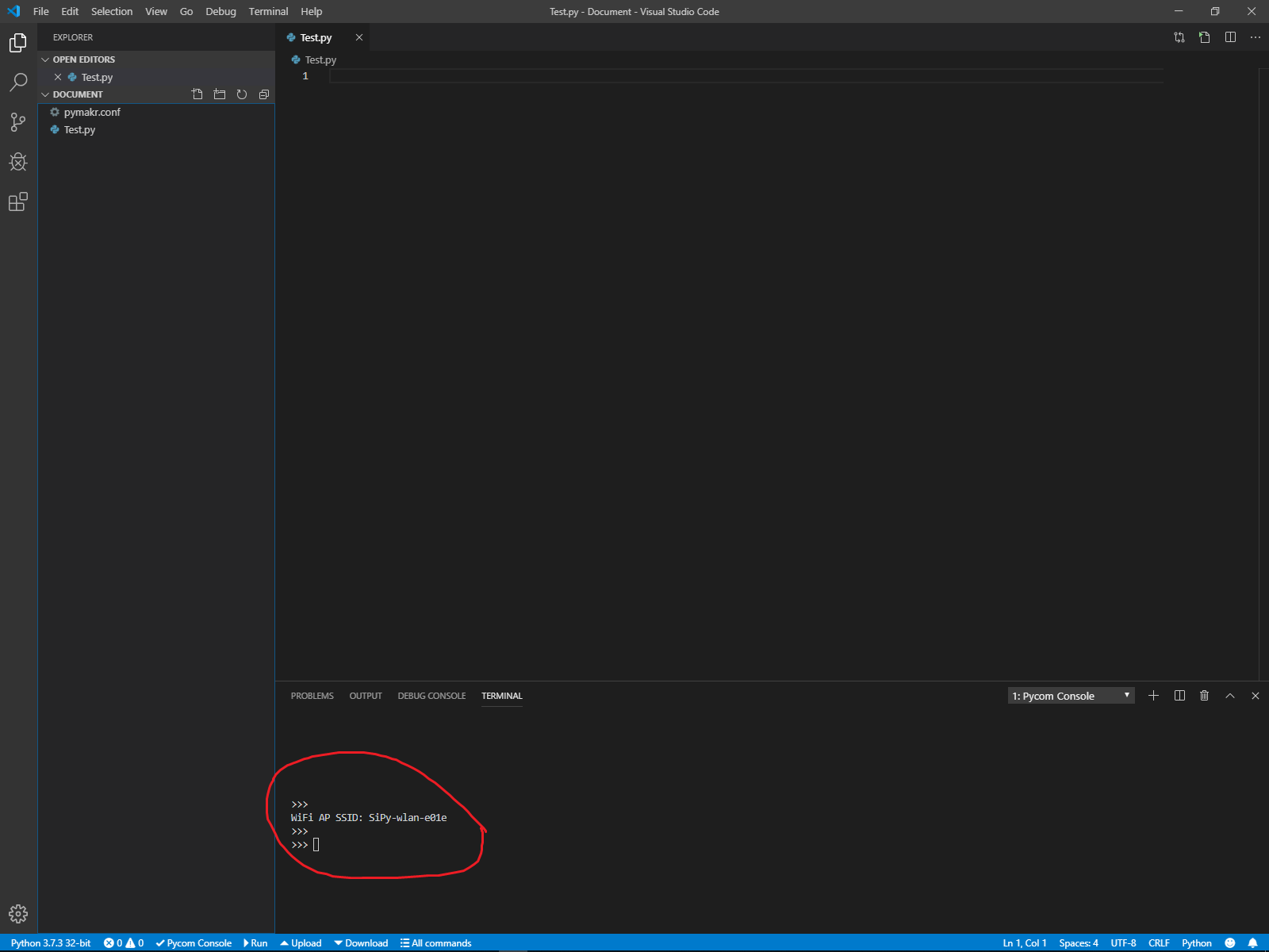
Next you will need to know the SiPy Module SSID which can be found using all commands and pressing get WiFI AP SSID. Each SiPy Module SSID will be unique but the password is the same throughout and cannot be changed. Password for SiPy Module SSID is www.pycom.io
Note: Desktop Users will need to get a WiFi adapter
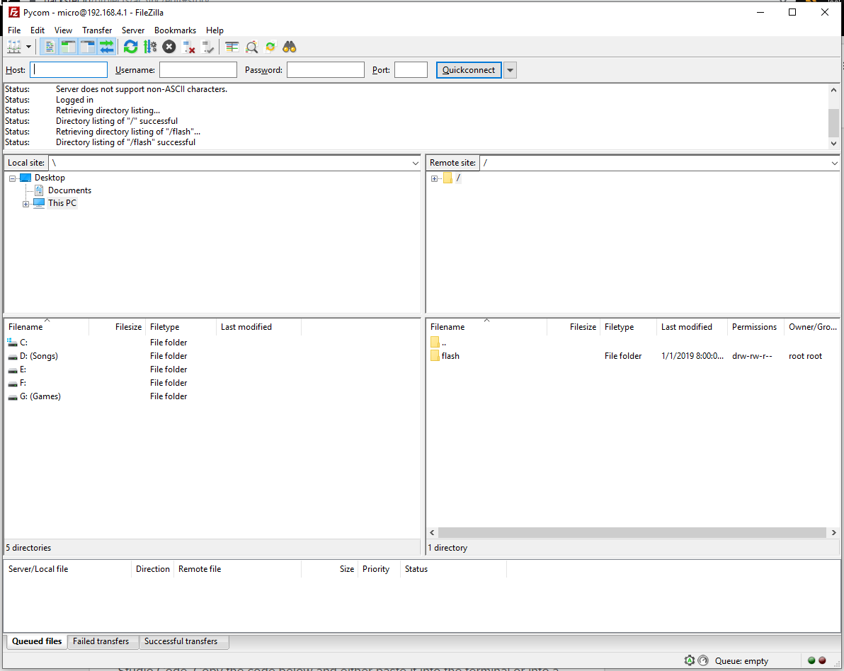
Now you can start using filezilla to access the SiPy Flash! Firstly connect to the SiPy SSID, then go to filezilla site manager and connect to the new site you created and type in the password. Now open the flash folder and delete main.py ONLY! After deleting the main.py, restart the SiPy and you can start running/uploading your programs.
Note: You might want to copy the flash folder onto your OS (Operating System) in case you delete everything.
5. Registering with Sigfox BackendAfter installing Visual Studio Code, connect the pycom extension board to the computer and it will automatically detect the connection when you open Visual Studio Code. Copy the code below and either paste it into the terminal or into a file and run it. Either method will do.
from network import Sigfox
import binascii

# initalise Sigfox for RCZ* (You may need a different RCZ Region)
sigfox = Sigfox(mode=Sigfox.SIGFOX, rcz=Sigfox.RCZ*)

# print Sigfox Device ID
print(binascii.hexlify(sigfox.id()))

# print Sigfox PAC number
print(binascii.hexlify(sigfox.pac()))Note: Replace * with your RCZ Region Number.
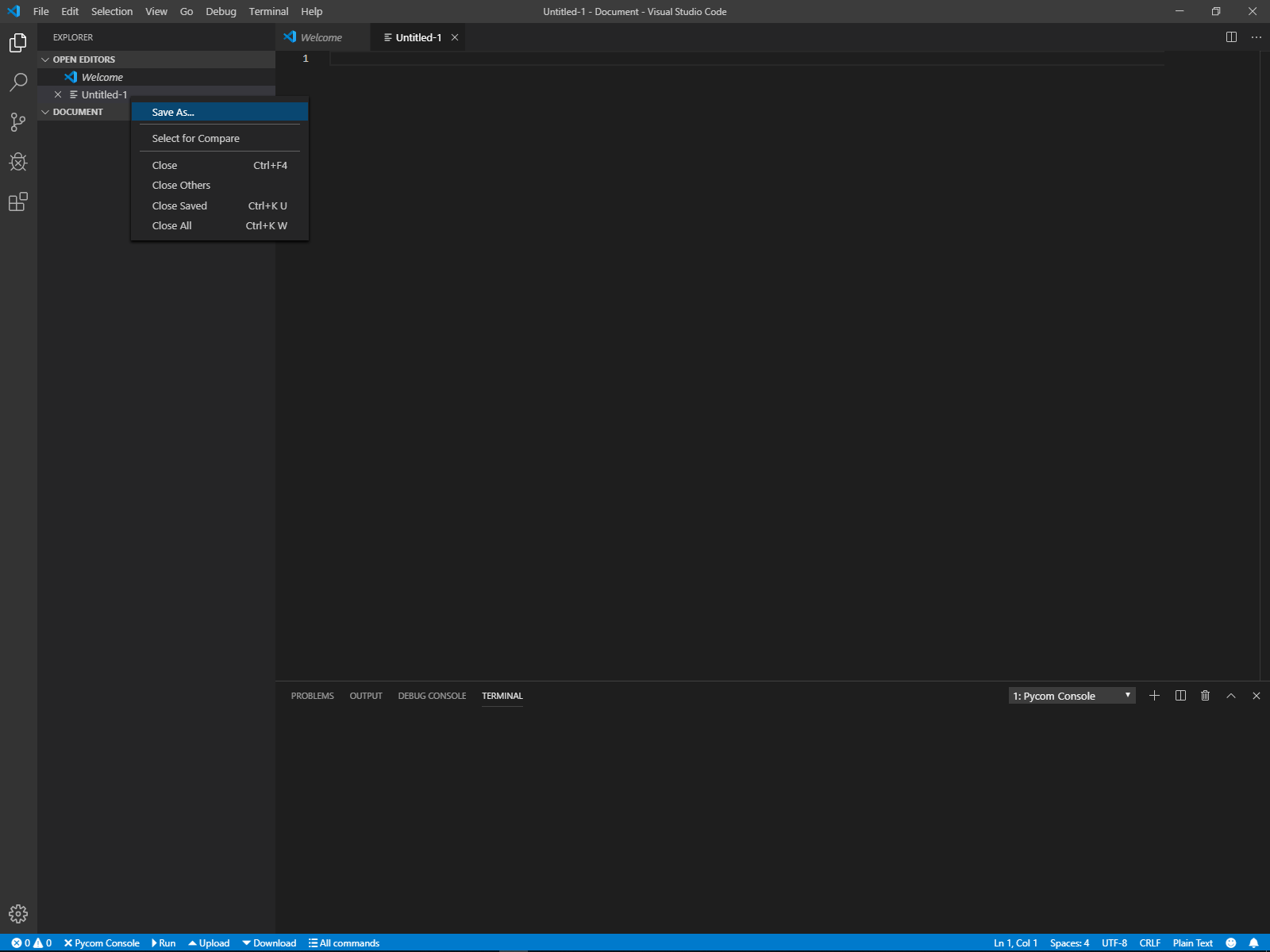
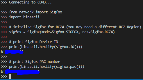
Terminal Method to get Sigfox Device ID and PAC number
To bring up the terminal in Visual Studio Code Press Ctrl+~. Then paste the code inside and it will show like the following picture.
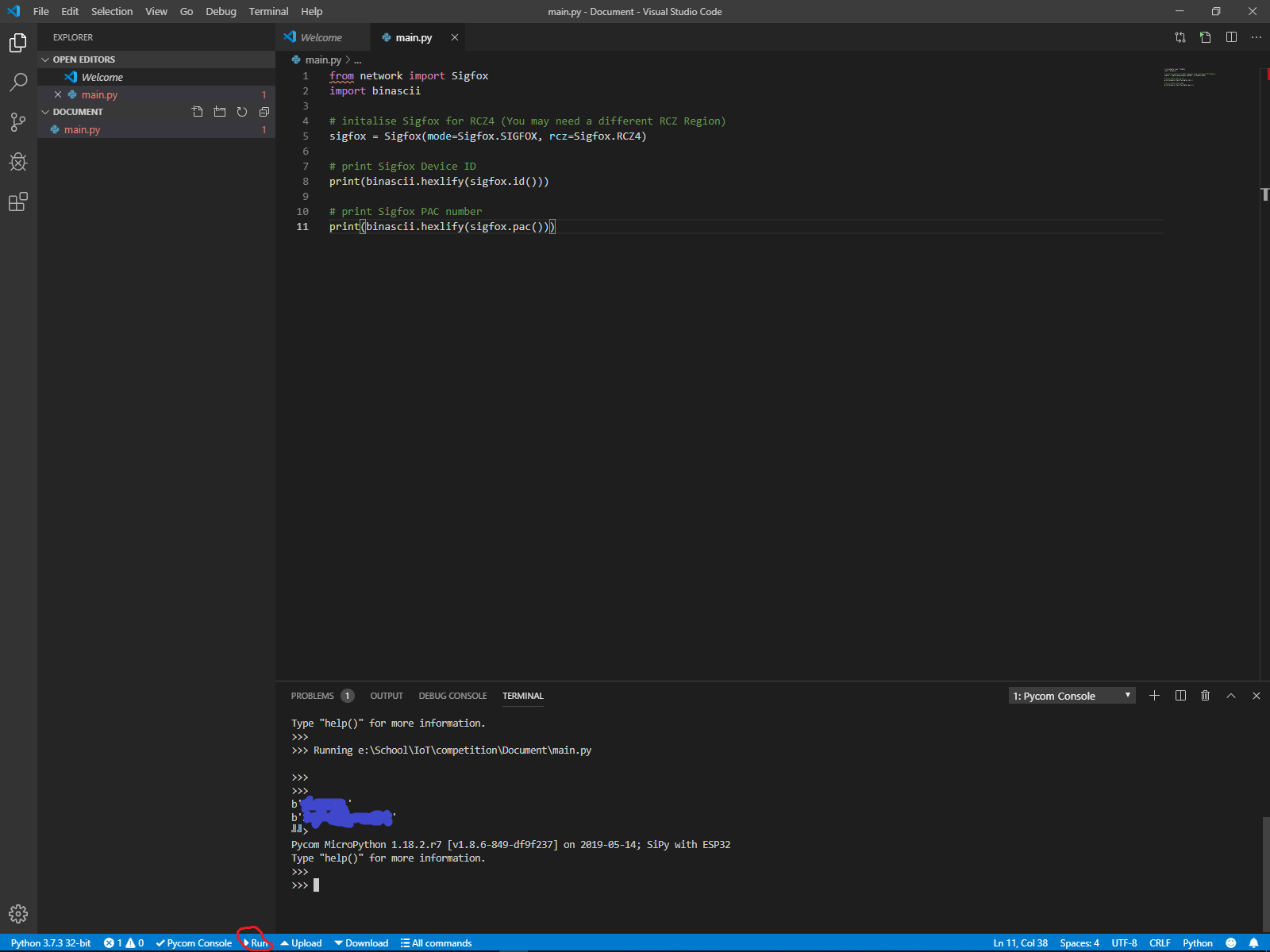
File Method to get Sigfox Device ID and PAC number
Once the new file is saved by pressing Ctrl+S or going to file then save, paste the code into the file and save the file then you can run the file by pressing the run button at the bottom of the screen and should get the same as the picture below.
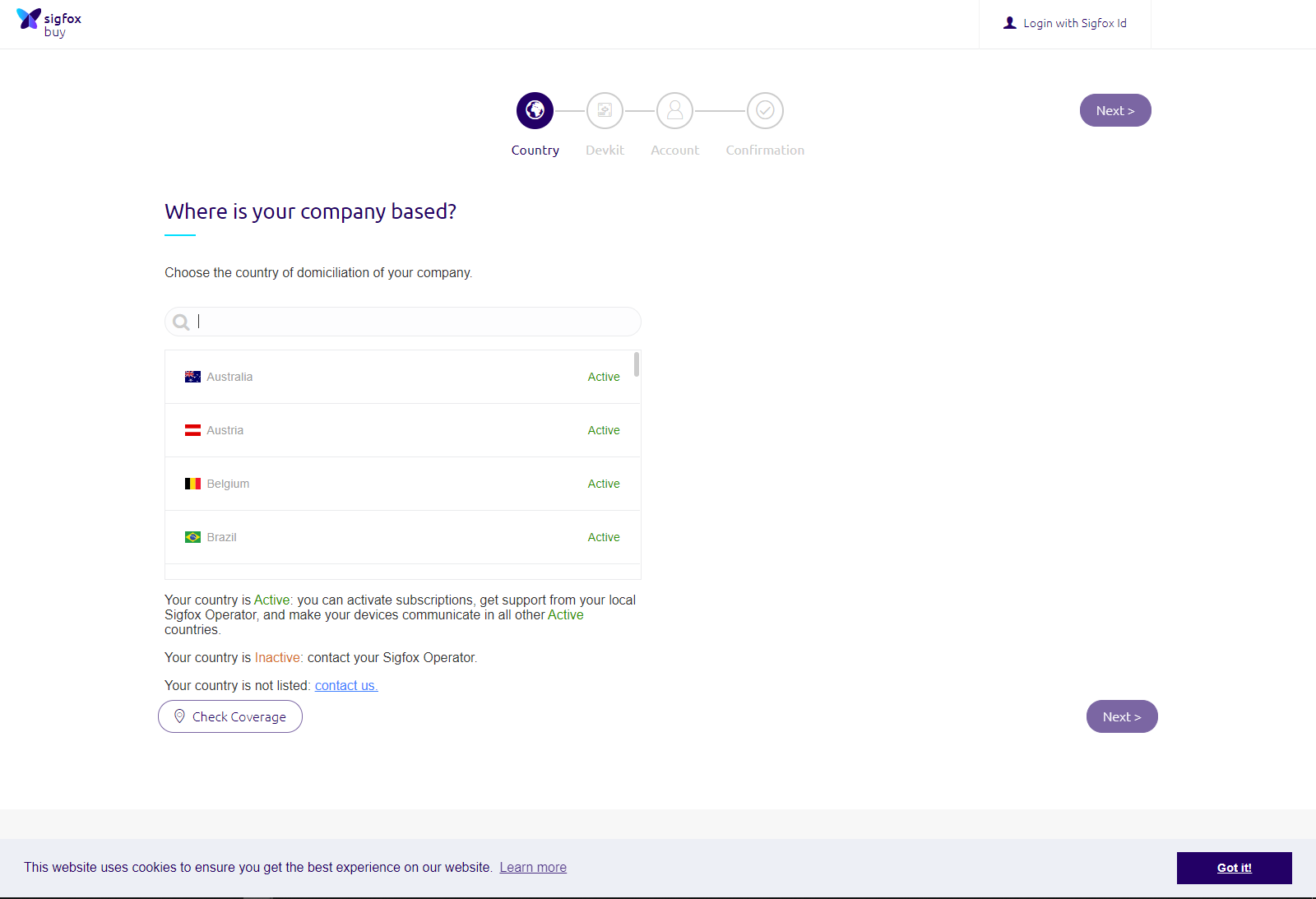
After getting your Sigfox Device ID and PAC number, you will need to register your Sigfox to the Sigfox Backend before you can start transmitting to it. The first page you see will be where is your sigfox company based. You have to choose the country in which this Sigfox device will be used in as each of the Sigfox Zones are configured differently.
After choosing the correct country, the next page will require your Sigfox Device ID and PAC number which you have gotten in the beginning of this chapter. Paste them into correct field and the page should look like the picture blow. As for the rest fill up accordingly.
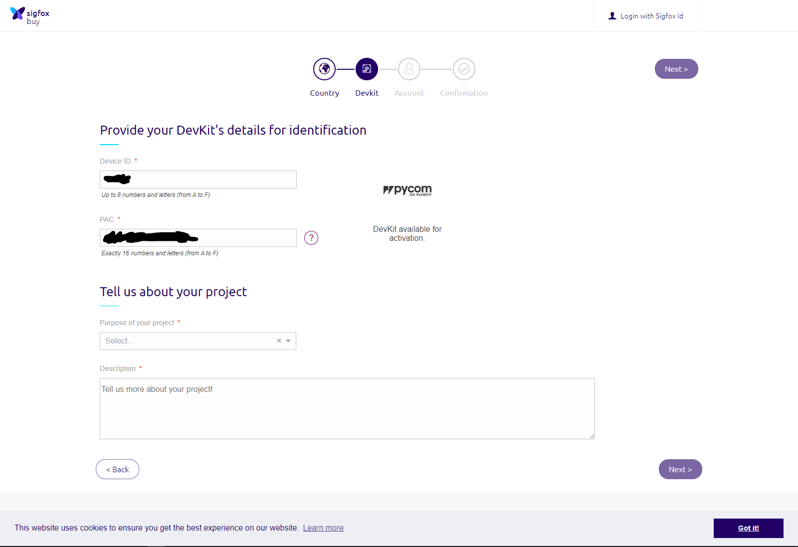
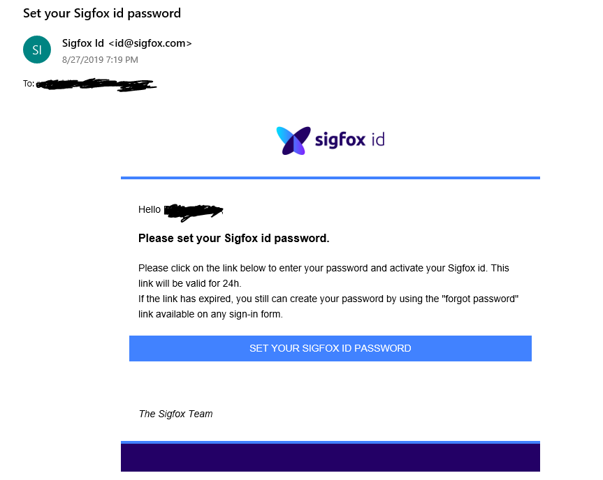
After filling up the device page, Create a Sigfox Account or login to an existing Sigfox Account, you have to register the Sigfox to your account. If your're creating a new Sigfox Account, Sigfox will send you an email to the registered email to set up the password.
After you have setup your sigfox backend account, you can run this code to send up some data to see if the backend can receive them.
Note**: Connect your sigfox antenna first before running any sigfox program.
from network import Sigfox
import socket

# initalise Sigfox for RCZ* (You may need a different RCZ Region)
sigfox = Sigfox(mode=Sigfox.SIGFOX, rcz=Sigfox.RCZ*)

# create a Sigfox socket
s = socket.socket(socket.AF_SIGFOX, socket.SOCK_RAW)

# make the socket blocking
s.setblocking(True)

# configure it as uplink only
s.setsockopt(socket.SOL_SIGFOX, socket.SO_RX, False)

# send some bytes
s.send(bytes([1, 2, 3, 4, 5, 6, 7, 8, 9, 10, 11, 12]))Note: Replace * with your RCZ Region Number.
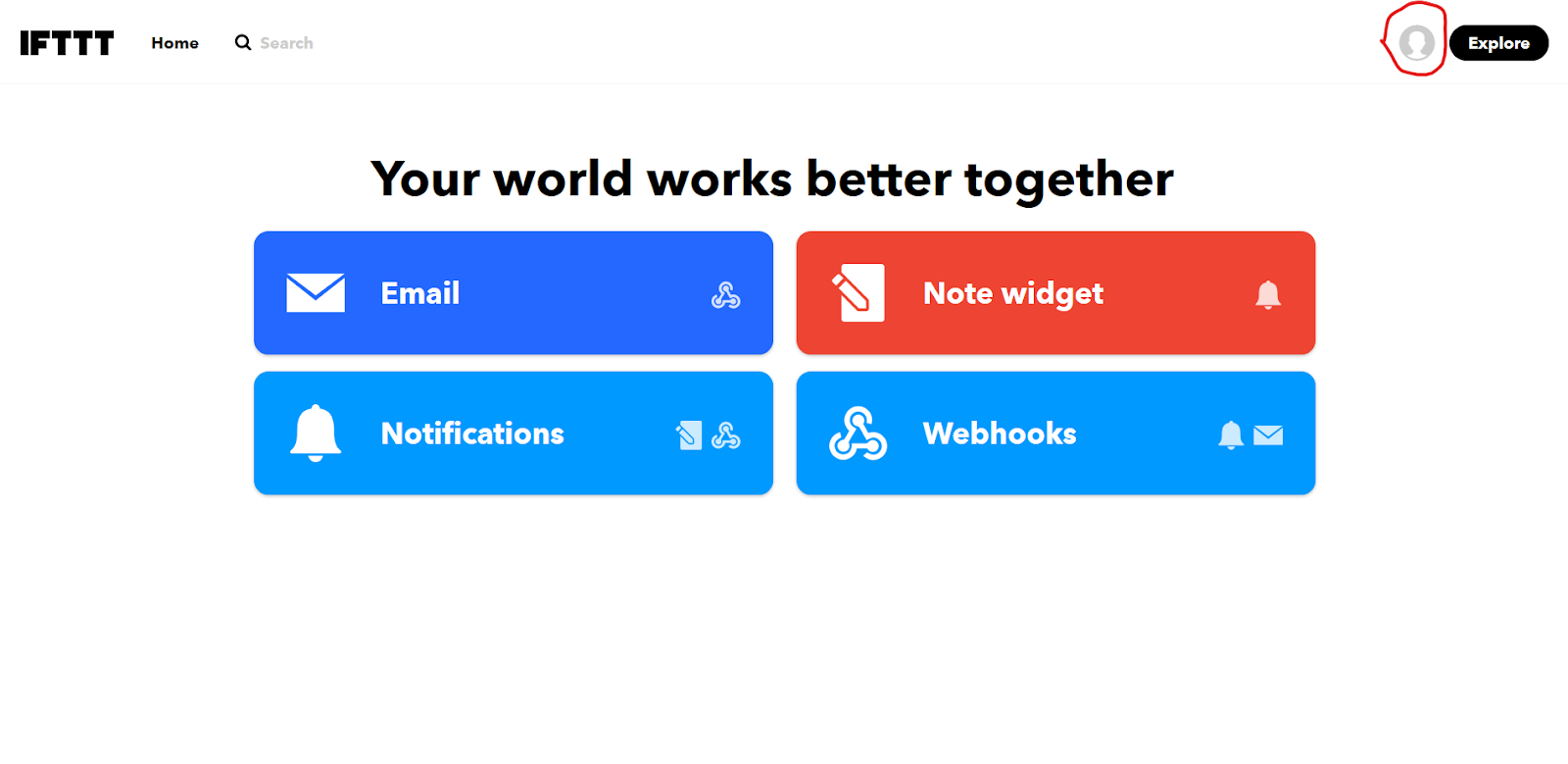
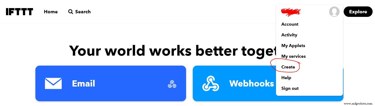
6. Setting up the CloudFirstly, you will have to setup the IFTTT for emailing, go to the IFTTT website and create an account. After setting up the account and logging in, go to your profile which is located near the top right corner of the screen on the left side of the “Explore” and press on the Create.
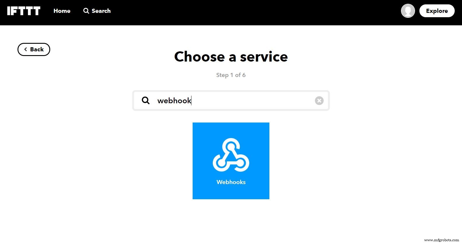
Click "This" and then search for Webhooks and press it. If you are unsure, the following pictures will help you with what to do.

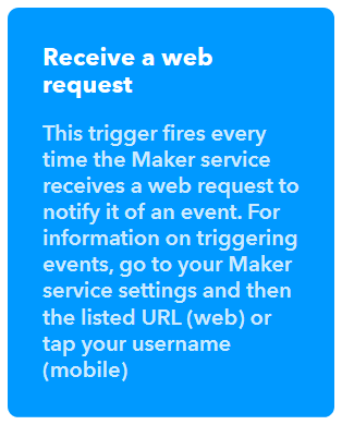
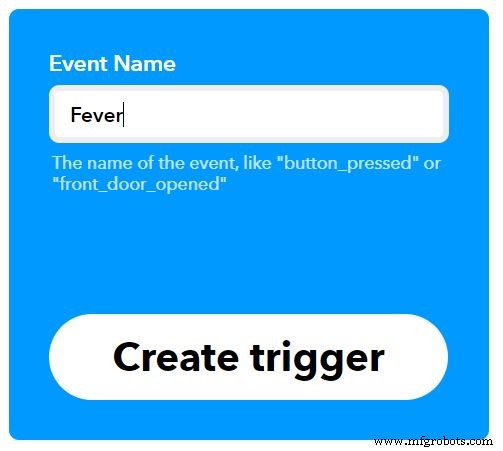
After selecting Webhooks, press the Receive a web request box and enter an event name to fit your requirements (in this example fever is used), afterwards press Create trigger.
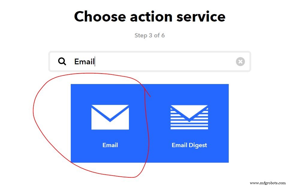
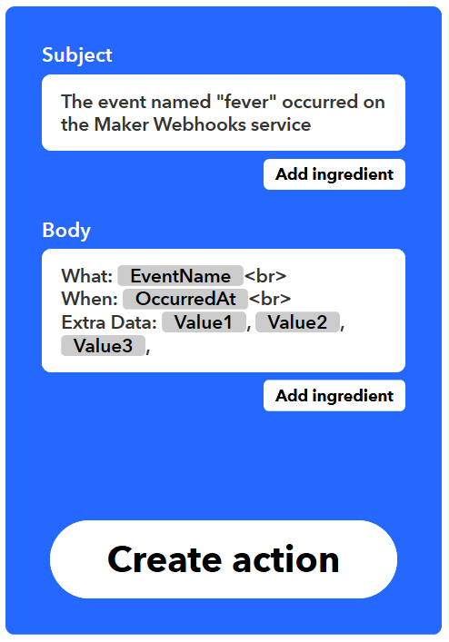
Press the word "That", type email in the search box and press Email then press Send me an email box

Enter message information. You can pass data about the event that triggered your message by using ingredients. For example, including {{Event Name}} adds the event name to your text message. The Body section must include at least {{Value1}} and {{Value2}}. Click Create action to finish the new applet. Note: Value 1, value 2 and value 3 in body message are derived from MATLAB Analysis and can be modified according to your requirement
ThingSpeak is an IOT (Internet of Things) platform which can be easily setup, learned and is open source.
First, we create two channels; (SIGFOX) TEMPERATURE PRIVATE VIEWING & (SIGFOX) TEMPERATURE PUBLIC VIEWING.
For the (SIGFOX) TEMPERATURE PRIVATE VIEWING, its purpose is to obtain data from the Sigfox backend. Sigfox sends up using bytes, this is because, we have realised that Ubidots (a web service) do not really work well with decoding Strings, so to make it work and accessible with both ThingSpeak and Ubidots, we chose to use bytes as it contain numbers from 0-255.
Therefore, using bytes makes it so we have to send both the whole number and the decimal number of the temperature information separately. So, this channel is mainly for keeping these messy values, later transferring to another channel for viewing which is the (SIGFOX) TEMPERATURE PUBLIC VIEWING channel.
We use MATLAB Analysis to convert the two messy values (whole number & decimal number) into just one combined value and transfer it onto the other channel. At the same time, we also transfer the userID onto the (SIGFOX) TEMPERATURE PUBLIC VIEWING as it's used for viewing. The MATLAB script is triggered on data insertion using a ThingSpeak REACT which will be explained below.
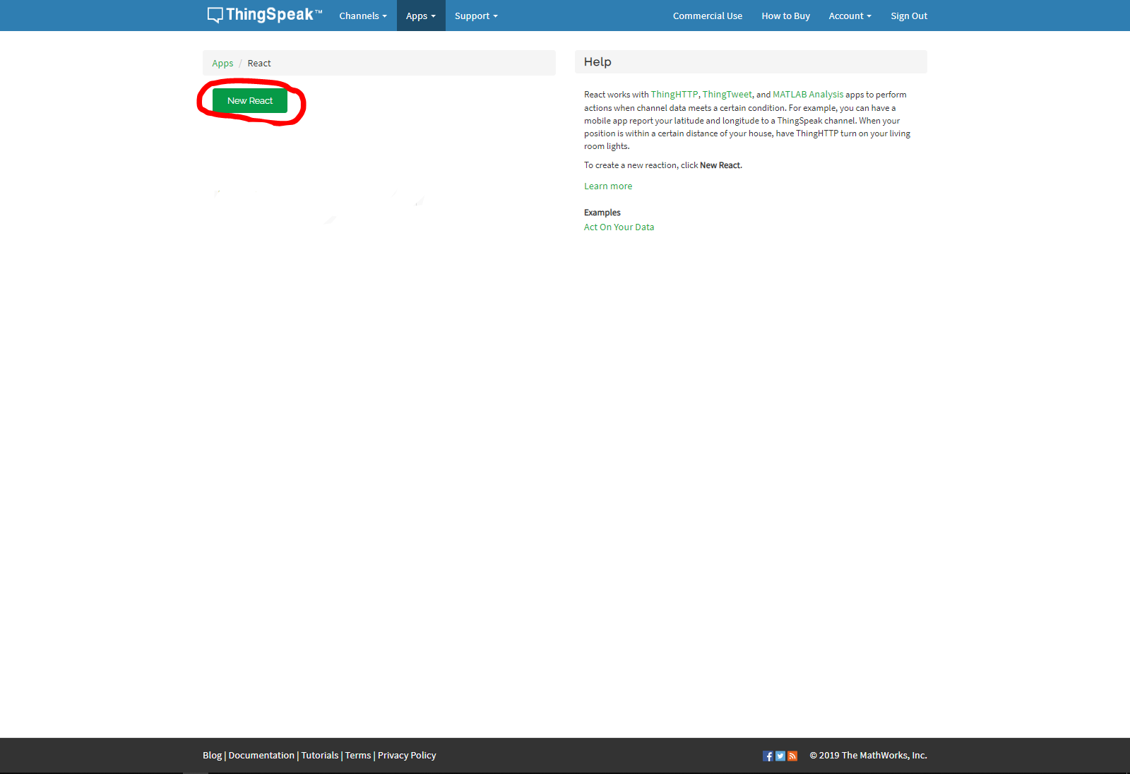
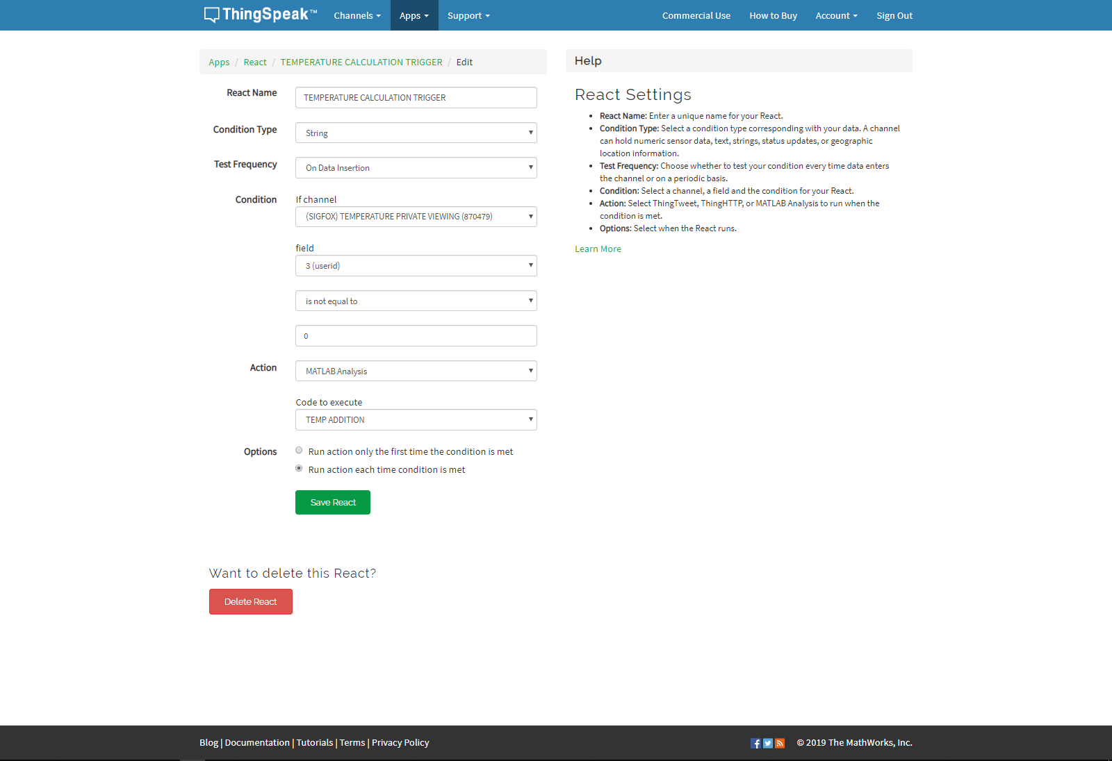
To setup the react, first go to Apps and then select React which will open the reacts tab. Press New React to create a new react for the MATLAB Analysis to be triggered when new data arrives from the Sigfox backend. Set the condition type to string, test frequency to on data insertion, condition to field 3 (which should be your userid) of the (SIGFOX) TEMPERATURE PRIVATE VIEWING when its not equal to 0, action to MATLAB Analysis with the code for calculating the temperature and Options to Run Action only the first time condition is met.

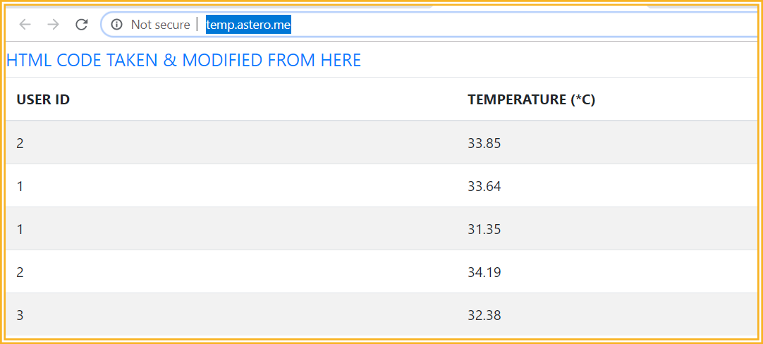
The table code was taken from an open sourced project and modified to suit our needs. It's very useful as the table auto updates every time a new data is sent in, perfect for our usage.
Unfortunately, the MATLAB plugin for the table is only view-able in private view and not in the public view. As it's intended for administrative purposes only, we do not subject this as an issue, it's intended to be only viewed in private view.
To retrieve Webhooks information, Click on your profile logo near the top right corner of the screen on the left of the “Explore” tab. Select My Services, select Webhooks then click documentation near the top right of the web page, from there you can see your key and format for sending a request. Enter that event name. The event name for this project is fever
https://maker.ifttt.com/trigger/{event}/with/key/(example)
https://maker.ifttt.com/trigger/fever/with/key/(example)
The service can be tested to see if it works or not by pasting the URL(example of the URL are shown above) into your browser or pressing the test button upon creation of the webhooks and email applet

After all that is done, you should be able to receive an email like the following picture, after you have finished setting up the ThingSpeak React.
Aden - RaspberryPi + Arduino + its modules + ThingSpeak (MATLAB+ Setup)
Reginald - Sigfox + ThingSpeak Data Collection + Schematics
Bo Sheng - IFTTT Setup
Code
- [C] ARDUINO NANO
- [PYTHON] RaspberryPi
- [MicroPython] Sigfox (Pycom)
- [ThingSpeak] MATLAB SCRIPT
[C] ARDUINO NANOArduino
This code is used for checking if there's a RFID card tap, if there is, there will be temperature taking and also handshaking between the Raspberry Pi to send data over like the card's ID, temperature and ready/standby signal and more.It also uses LCD to show informative information.
If you're interested in knowing more, please read the section on "HOW IT WORKS: RaspberryPi & Arduino"
/*
90% is coded from scratch by Aden,
http://www.astero.me

the other 10% consists of open sourced libraries(Credits found below) used, like the RFID & temperature module.

*/

/*
 * Initial Author: ryand1011 (https://github.com/ryand1011)
 *
 * Reads data written by a program such as "rfid_write_personal_data.ino"
 *
 * See: https://github.com/miguelbalboa/rfid/tree/master/examples/rfid_write_personal_data
 *
 * Uses MIFARE RFID card using RFID-RC522 reader
 * Uses MFRC522 - Library
 * -----------------------------------------------------------------------------------------
 *             MFRC522      Arduino       Arduino   Arduino    Arduino          Arduino
 *             Reader/PCD   Uno/101       Mega      Nano v3    Leonardo/Micro   Pro Micro
 * Signal      Pin          Pin           Pin       Pin        Pin              Pin
 * -----------------------------------------------------------------------------------------
 * RST/Reset   RST          9             5         D9         RESET/ICSP-5     RST
 * SPI SS      SDA(SS)      10            53        D10        10               10
 * SPI MOSI    MOSI         11 / ICSP-4   51        D11        ICSP-4           16
 * SPI MISO    MISO         12 / ICSP-1   50        D12        ICSP-1           14
 * SPI SCK     SCK          13 / ICSP-3   52        D13        ICSP-3           15
*/
/*****************
  This is a library example for the MLX90614 Temp Sensor
  Designed specifically to work with the MLX90614 sensors in the
  adafruit shop
  ----> https://www.adafruit.com/products/1748
  ----> https://www.adafruit.com/products/1749
  These sensors use I2C to communicate, 2 pins are required to
  interface
  Adafruit invests time and resources providing this open source code,
  please support Adafruit and open-source hardware by purchasing
  products from Adafruit!
  Written by Limor Fried/Ladyada for Adafruit Industries.
  BSD license, all text above must be included in any redistribution
 ******************/

// INCLUDE NECESSARY HEADER FILES

#include <SPI.h>
#include <MFRC522.h>
#include <LiquidCrystal_I2C.h>
#include <Wire.h>
#include <SoftwareSerial.h>
#include <Adafruit_MLX90614.h>


// DEFINITION OF PINS

#define RST_PIN         9           // Configurable, see typical pin layout above
#define SS_PIN          10          // Configurable, see typical pin layout above
#define BUZZER_PIN      7           //Pin define for Buzzer
#define LED_PIN         6           //Pin define for LED
#define dist_sensePin A0

MFRC522 mfrc522(SS_PIN, RST_PIN);   // Create MFRC522 instance.

LiquidCrystal_I2C lcd(0x27,16,2);   // Calls the LiquidCrystal class and creats an instance for the LCD.
// set the LCD address to 0x27 with 16 chars and 2 line display

Adafruit_MLX90614 mlx = Adafruit_MLX90614();  // Calls the Adafruit MLX90614 instance.
SoftwareSerial unoSerial(2, 3); // RX, TX	  // Calls the SoftwareSerial instance (for Pycom communication)


// GLOBAL VARIABLES

boolean tapped = true;
boolean confirmation = false;

String GetUID(){
  String card_UID= "";
  String card_UID_no_space = "";
   for (byte i = 0; i < mfrc522.uid.size; i++)
  {
     card_UID.concat(String(mfrc522.uid.uidByte[i] < 0x10 ? " 0" : " "));
     card_UID.concat(String(mfrc522.uid.uidByte[i], HEX));
  }

  card_UID_no_space.concat(card_UID.charAt(1));
  card_UID_no_space.concat(card_UID.charAt(2));
  card_UID_no_space.concat(card_UID.charAt(4));
  card_UID_no_space.concat(card_UID.charAt(5));
  card_UID_no_space.concat(card_UID.charAt(7));
  card_UID_no_space.concat(card_UID.charAt(8));
  card_UID_no_space.concat(card_UID.charAt(10));
  card_UID_no_space.concat(card_UID.charAt(11));
  //Serial.println(card_UID_no_space);
  return card_UID_no_space;
}

void setup() {
  Serial.begin(9600);                                           // Initialize serial communications with the PC


  while(!confirmation)
  {
    Serial.println("ARDUINO");
    confirmation = Serial.readString() == "RAPI";
    delay(1000);
  }

  SPI.begin();                                                  // Init SPI bus
  mfrc522.PCD_Init();                                           // Init MFRC522 card

  mlx.begin();  												// Initiates Adafruit MLX90614
  unoSerial.begin(9600);										// Initiates SoftwareSerrial with 9600 baud rate.


  // Setting which pins are supposed to be outputs.
  pinMode(BUZZER_PIN, OUTPUT);
  pinMode(LED_PIN, OUTPUT);

  lcd.init();													// Initiates the LCD screen.
  lcd.backlight();												// Turns on the backlight for the LCD.

}

void loop() {
  // put your main code here, to run repeatedly:

  boolean readySignal = Serial.readString() == "READY";			// Creates a boolean that checks if the "ready signal" is received.


  if(readySignal) // If it's received,
  {
    tapped = true; // Set tapped to true.
    Serial.println("RECEIVED"); // And return "RECEIVED" through Serial Communication.


  }


  if(tapped) // If it's ready to be tapped,
  {

    digitalWrite(BUZZER_PIN, 0);
    digitalWrite(LED_PIN, 0);

    lcd.clear();
  	// Clear the Buzzer, LED & LCD.

    lcd.setCursor(0,0);
    lcd.print("   Please tap");
    lcd.setCursor(0,1);
    lcd.print("   your card.");

	// And later set a message on the LCD screen to prompt the user to tap the card.


    delay(500); // Delay for 500 ms.
    tapped = false; // Set the tapped boolean back to false so no taps can be done in this phase.
  }
  else
  {
    String card_UID= "";

    // Look for new cards
    if ( ! mfrc522.PICC_IsNewCardPresent()) {
      return;
    }

    // Select one of the cards
    if ( ! mfrc522.PICC_ReadCardSerial()) {
      return;
    }

    card_UID = GetUID();
    card_UID.toUpperCase();
    Serial.print(card_UID);
    Serial.print("\n");


    String rawData = Serial.readString(); // Read the incoming String and puts it into a String variable.
    int commaPos = rawData.indexOf(','); // Finds the position of the comma in the string read above.

    String userInitial = rawData.substring(0, commaPos); // Sub strings the rawData string so it only reads any words that is before the comma's position.
    int userID = rawData.substring(commaPos + 1).toInt(); // After wards, save what's behind the comma, which is supposed to be an integer.


    lcd.clear(); // Clear the LCD screen.

    if(userID != 0 && userInitial != "0") // Check if it's actually a valid user tapping (validated by the RaspberryPi.)
    {

      lcd.setCursor(0,0);
      lcd.print("Welcome, ");

      lcd.setCursor(0,1);
      lcd.print(userInitial);


	  // And later set a message, welcoming the user.

      String sMeasTemp = "";

      int dist_senseValue = analogRead(dist_sensePin); // Checks the analog value of the distance module.
      byte temp_Hbyte = 0; // Creates a byte variable that initialises to 0.
      byte temp_Lbyte = 0; // Creates a byte variable that initialises to 0.

      float meas_temp = 0.0; // Creates a float variable that initialises to 0.


      delay(2000); // Delay for 2 seconds.

      while((dist_senseValue < 170) || (dist_senseValue > 200)) // Check if there is actually a valid user infront of the machine. If no, it'll keep looping what's under.
      {

        dist_senseValue = analogRead(dist_sensePin); // Keep checking until there's a person that comes in the distance sensor's range.

        lcd.setCursor(0,0);
        lcd.print("Please take");
        lcd.setCursor(0,1);
        lcd.print("your temperature.");

		// Prompt the user to take their temperature by standing infront of the machine.

      }


      digitalWrite(BUZZER_PIN, 1);
      digitalWrite(LED_PIN, 1);

      lcd.clear();
	  // Turns on the Buzzer and LED, at the same time, clear the LCD too.


      meas_temp = (float)mlx.readObjectTempC();

      temp_Hbyte = floor(meas_temp);
      temp_Lbyte = (meas_temp - temp_Hbyte) * 100;

      sMeasTemp += userID;
      sMeasTemp += ",";
      sMeasTemp += temp_Hbyte;
      sMeasTemp += ",";
      sMeasTemp += temp_Lbyte;

	  // Collect the temperature data that is taken.

      Serial.println("TEMP");
      Serial.println(meas_temp); // Transfer the temperature data through Serial Communication to the RaspberryPi.


      if((meas_temp >= 28) && (meas_temp <=42)) // Check if it's a valid temperature.
        unoSerial.print(sMeasTemp); // If it is, send to the sigfox module for cloud storage.

      lcd.setCursor(0,0);
      lcd.print("Temperature: ");
      lcd.setCursor(0,1);
      lcd.print("   " + String(meas_temp));

	  // Shows the temperature of the user through the LCD screen.
    }
    else // If it's an invalid user,
    {
      lcd.setCursor(0,0);
      lcd.print("Error!");
      lcd.setCursor(0,1);
      lcd.print("Invalid User.");

	  // Tells the user that he's not a valid user and he is unable to proceed to the temperature taking phase.


    }

    rawData = Serial.readString();
    commaPos = rawData.indexOf(',');
    userInitial = rawData.substring(0, commaPos);

	// Above reads the incoming rawData again and converts into a userInitial variable.

    if(userInitial == "0") // If the user initial sent back is 0, it means that it's an invalid temperature because the RaspberryPi is unable to process it.
    {
      lcd.clear();


      lcd.setCursor(0,0);
      lcd.print("Error!");
      lcd.setCursor(0,1);
      lcd.print("Invalid Temperature.");

	  // Prompts the user it's an invalid temperature range.
    }

   Serial.println("STANDBY");
   // Sends Serial that the Arduino is still processing data.

    delay(1000); // Delay for 1 second.
    mfrc522.PICC_HaltA();
    mfrc522.PCD_StopCrypto1();
  }
 }
[PYTHON] RaspberryPiPython
This code is mainly used for updating the MySQL database and also to handshake with the Arduino via Serial Communication. It plays a vital role with the Arduino in this projectIf you're interested in knowing more, please read the section on "HOW IT WORKS: RaspberryPi & Arduino".
'''
Coded from scratch by Aden; for the Hackster.io Sigfox competition.
http://www.astero.me
'''
# IMPORTS
import mysql.connector
import serial
import os
import time
# METHODS
def queryConnection():
cursor = conn.cursor(buffered=True)
cursor.execute("USE `" + databaseName + "`") # Use the userInfo database,
return cursor
# DATABASE INFORMATION
host = "localhost"
user = "root"
password = "password"
databaseName = "smartTemp"
conn = mysql.connector.connect(host=host, user=user,passwd=password)
# Serial Communication
comPort = 'ttyUSB0'
baudRate = 9600
ser = serial.Serial('/dev/' + comPort, baudRate, timeout=0) # Set the timeout as 0 so if it doesn't read a serial, it skips.
print("Confirming USB Serial Port now, please wait")
connected = False
# Below, is to ensure that the RaPi receives the correct COM port of the Arduino board.
for x in range(2):
time.sleep(2)
ser.write("RAPI") # Basically, here, we're writing to the Arduino to confirm communication.
if connected == False:
serialConfirmation = ser.readline().strip() == "ARDUINO" # Check if the RaPi is reading the correct COM port, whether it can read the Arduino's serial communications.
print(serialConfirmation)
if(serialConfirmation == False):
comPort = 'ttyUSB1'
connected = True
else:
comPort = 'ttyUSB0'
connected = True
print(comPort)
ser = serial.Serial('/dev/' + comPort, baudRate) # Re-initiates this variable again, this time without a Serial Communication timeout. Meaning, it'll try to communicate with the Arduino w/o a timeout.
print("COM PORT confirmed, using " + comPort) # Print to let you know which PORT the Arduino is on.
# File Creation
countFile = open("count.txt", "a++") # Creates a count file if it doesn't exist.
# GLOBAL VARIABLES
tapRFID = False
cursor = queryConnection()
if(os.stat("count.txt").st_size == 0): # Checks if the count.txt is empty.
print("Count has not been set, setting to 1 now.")
count = 1
else:
for countNumber in countFile:
count = int(countNumber) # Set the count to the last counted count.
print("Count has been restored from previous session: " + str(count))
try: # Tries to create the database if it doesn't already exists.
print("Creating " + databaseName + " database now..")
cursor.execute("CREATE DATABASE " + databaseName) # Create a database.
print("Database has been sucessfully created.")
except(mysql.connector.errors.DatabaseError): # If the database already exists, it excepts here.
print(databaseName + " database is already created.") # If that database is found, run this block of code instead.
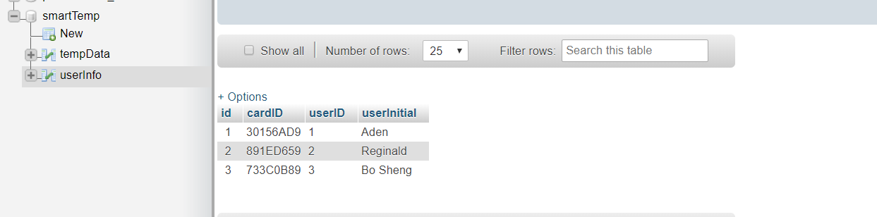
cursor.execute("CREATE TABLE IF NOT EXISTS `userInfo` (id int, cardID VARCHAR(9), userID VARCHAR(4), userInitial VARCHAR(8))") # Create a userInfo table if it doesn't exist.
cursor.execute("CREATE TABLE IF NOT EXISTS `tempData` (id int, userID VARCHAR(4), dateMeas date, timeMeas time, tempMeasure decimal(5,2))") # Create a tempData table if it doesn't exist.
while True: # Endless loop.
cursor = queryConnection() # Re-establishes the query connection using the queryConnection() method.
cardID = str(ser.readline().strip()) # Reads the serial line and converts it to a String, stripping any empty spaces.
cursor.execute("SELECT * FROM userInfo WHERE cardID = '" + cardID + "'") # Select the userInfo table with the inputted cardID from the Arduino.
items = cursor.fetchone() # Fetch one line of the table.
if(items != None): # If it's able to fetch (valid user)
print(cardID) # Print out the cardID that it's currently fetching.
userID = str(items[2]) # Gets the userID from the fetched line.
userDetails = str(items[3] + ", " + items[2]) # Get the userDetails from the fetched line.
# Get the currentDate & currentTime.
currentDate = str(time.strftime("%Y-%m-%d %H:%M:%S", time.gmtime()))[0:10]
currentTime = str(time.strftime("%Y-%m-%d %H:%M:%S", time.gmtime()))[11:]
print(items) # Print the whole item array that was fetched. (for debugging)
ser.write(b'' + userDetails) # Serial communication to the Arudino.
countFile.close() # Closes the count file.
countFile = open("count.txt", 'w') # Makes it so it overwrites the count file with the new saved count below.
tempSignal = False
while(tempSignal == False): # Keeps looping until it gets the temperature reading from the Arduino.
print("Getting Temperature")
tempSignal = ser.readline().strip() == "TEMP" # Read the Arudino incoming serial.
tempData = float(ser.readline().strip()) # Read the Arduino incoming serial of the temperature data.
print(tempData) # Prints the retrieved temperature data from the Arduino.
if(tempData >= 28 and tempData <= 42): # Check if the temperature is of a valid range.
cursor.execute("INSERT INTO `tempData`(`id`, `userID`, `dateMeas`, `timeMeas`, `tempMeasure`) VALUES (" + str(count) + ",'" + userID + "','" + currentDate + "','" + currentTime + "','" + str(tempData) + "')") # Write into the database the necessary information.
conn.commit() # Commit the INSERT changes into the database.
count = count + 1 # Ups the count.
countFile.write(str(count)) # Update the count file with the new count.
else: # If it's not a valid temperature.
ser.write(b'' + "0, 0") # Serial Communication to the Arduino informing that it's invalid temperature.
else: # If it's not a valid user.
ser.write(b'' + ", 0") # Serial Communication to the Arduino informing that no valid cardID is found.
print("Nothing found")
readySignal = ser.readline().strip() == "STANDBY" # Waits for the Arduino to tell that it's ready to do it again, to read/validate data.
while(readySignal == True): # If the Arduino is ready, loop until we're able to tell him back that we're also ready for another session.
ser.write(b'' + "READY") # Serial communication basically to say we're ready too.
print("sending")
receivedSignal = ser.readline().strip() == "RECEIVED"
if(receivedSignal == True):
readySignal = False
print("received")
cursor.close() # Close the query connection to prevent memory leaks.
conn.close() # Closes the connection to the MySQL.
[MicroPython] Sigfox (Pycom)Python
This code is mainly used to read the serial communication from the Arduino and upload the received values to the Sigfox backendIf you're interested in knowing more, please read the section on "HOW IT WORKS: Sigfox (Pycom)"
'''
100% is coded by Reginald,


'''
from machine import UART # Tx and Rx (``P3`` and ``P4``)
from network import Sigfox # Import the sigfox library from the pycom controller
import binascii # Import the Binary to ASCII library for converting from Binary (1,0) to ASCII (readable characters)
import socket # Import socket module to enable socket connection for Sigfox
import time # Import time that can be used for delays
import pycom # Import pycom module that contains fucntions that controls the pycom device
import sys # Import sys module to enable exit from the pycom running program
pycom.heartbeat(False)

#init Sigfox for RCZ4 (Asia)
sigfox = Sigfox(mode=Sigfox.SIGFOX,rcz=Sigfox.RCZ4)

uart1 = UART(1, baudrate=9600) # To set the serial communcation parameters
uart1.init(9600,bits=8,parity=None, stop=1, pins = ('P3', 'P4'), timeout_chars=20) # To set the serial communcation parameters


while True:
    try:
        recv=uart1.readline() # It always reads the serial communcation for any messages

        if recv != None:    '''If there is a message recieved from the serial communcation,
                            it will procced to establish the sigfox connection and process the message for sending'''

            #print Sigfox DeviceID
            print(binascii.hexlify(sigfox.id()))

            # print Sigfox PAC number
            print(binascii.hexlify(sigfox.pac()))

            #create Sigfox socket
            sk1 = socket.socket(socket.AF_SIGFOX, socket.SOCK_RAW)

            #make thesocket blocking
            sk1.setblocking(False)

            #configure as uplink only
            sk1.setsockopt(socket.SOL_SIGFOX, socket.SO_RX, False)

            dataList = recv.decode("utf-8")      #decode the received message
            print("dataList : %s" %(dataList))
            split_val = dataList.split(",")      #split the listing based on commas

			# eg. if receive message is 8,35,60  ->   userID = 8,  temperature = 35.60 degree celsius

			userID = int(split_val[0])           # assign the 1st element in the listing to userID.
            temp_H = int(split_val[1])           # assign the 2nd element in the listing to the whole number of the temperature.
            temp_L = int(split_val[2])           # assign the 3rd element in the listing to the decimal numner of the temperature.
            print("userID : %d temp_H : %d temp_L : %d" % (userID, temp_H, temp_L))
            bData = [userID,temp_H,temp_L]       # create a list
            print(bData)

            meas_temp = temp_H + (temp_L*0.01)   # merge temperature values
            print("measure temperature : %.2f" %(meas_temp))

		    sk1.send(bytes(bData))               #cast the data list to bytes and send to Sigfox backend.
            sk1.close()                          #close Sigfox socket connection.
            time.sleep(5)                        #delay for 5 seconds.

    except KeyboardInterrupt:
        sys.exit()
[ThingSpeak] MATLAB SCRIPTMATLAB
This script focuses on combining the raw data that is sent up by the Sigfox to ThingSpeak and put them together into a presentable visual state, allowing users to properly visualize the information. It also works alongside with IFTTT by triggering a webhook URL when it reaches a fever temperature, alerting user(s) via Email.If you're interested in learning more about this code, please read the section on "HOW IT WORKS: ThingSpeak".
%% Made from scratch by Aden; for the Hackster.io Sigfox Competition.
%% http://www.astero.me

readChannelID = 870479; %% Channel to read.

webhookTrigger = 'https://maker.ifttt.com/trigger/student_fever/with/key/h10MdSGwjSPtZQ43wH-AgoiKI0pwaljBNnGUEu4Yecn';

readAPIKey = 'QGHINBPNJQKULBH2'; %% Channel read API Key.


writeChannelID = 870482; %% Channel to write.

writeAPIKey = 'R6NJIM8NT5A42R9N'; %% Channel write API Key.


wholeNumber = thingSpeakRead(readChannelID, 'ReadKey', readAPIKey, 'Fields', 1); %% Read the value from field 1 and save it to a variable.

decimalNumber = thingSpeakRead(readChannelID, 'ReadKey', readAPIKey, 'Fields', 2)/100;
%% Read the value from field 2 and save it to a variable.

userID = thingSpeakRead(readChannelID, 'ReadKey', readAPIKey, 'Fields', 3);
%% Read the value from field 3 and save it to a variable.

display(wholeNumber, 'BEFORE') %% Display value for debugging.


analyzedData = wholeNumber + decimalNumber; %% Converting the two into one whole number instead of two separate values.


display(analyzedData, 'AFTER')


display(userID, 'USERID')


%%thingSpeakWrite(writeChannelID, analyzedData, 'Fields', 1, 'WriteKey', writeAPIKey);
thingSpeakWrite(writeChannelID,'Fields',[1,2],'Values',{analyzedData,userID},'WriteKey', writeAPIKey)

if(analyzedData >= 38) %% Check if fever temperature.
    webwrite(webhookTrigger,'value1',analyzedData,'value2',userID);     %% If yes, trigger the webhook and send an email of the values.
end
Schematics
How everything is connected together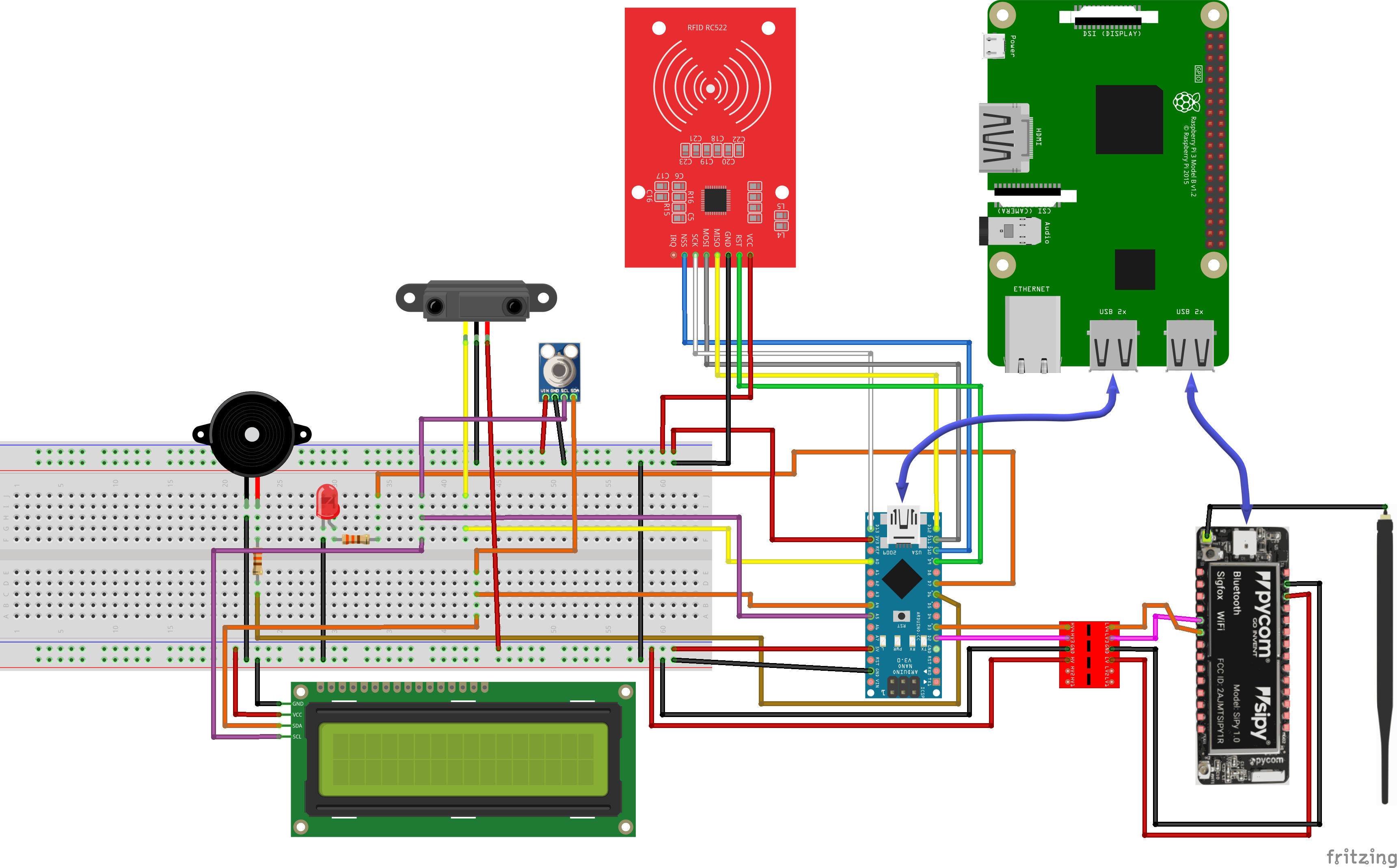 Connections for Distance Sensor for Arduino
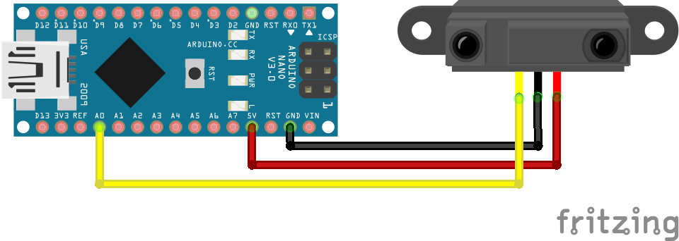 Connections for Temperature Sensor
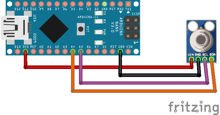 Connections for LED for Arduino
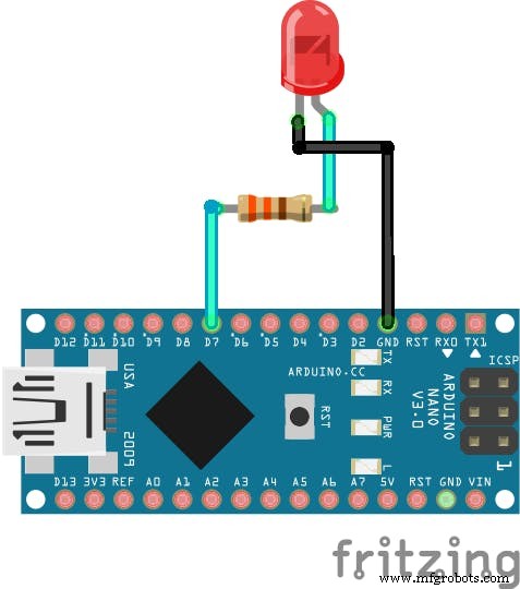 Connections for RFID for Arduino
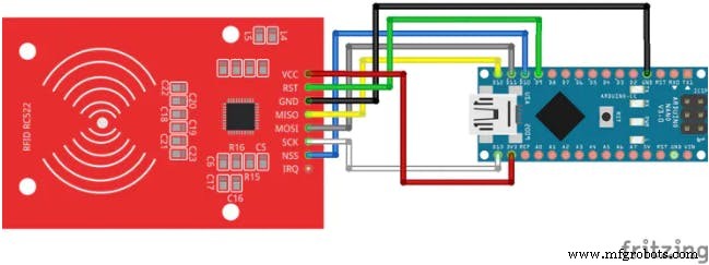 Connections for LCD for Arduino
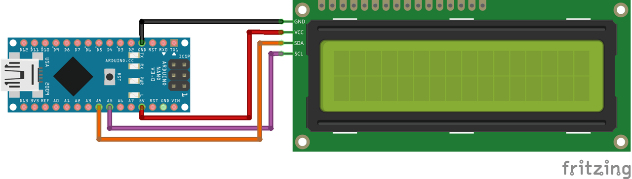 Connections for Buzzer for Arduino
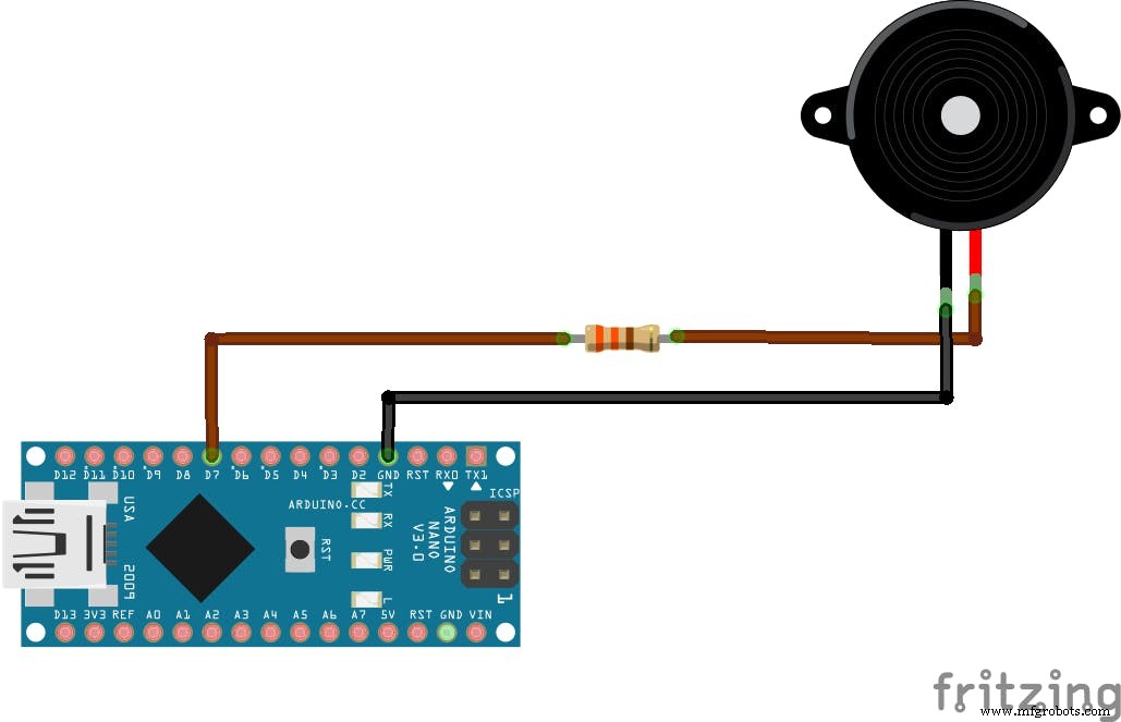
Manufacturing process
- Professional Raspberry Pi Temperature Monitoring with DS18B20
- Accurate Temperature Monitoring in a Server Closet with Raspberry Pi
- DIY Homebrew Temperature Control: Monitor & Regulate with Arduino
- Smart Blinds: Automated Light Control with Arduino & Solar Power
- Contactless Temperature Monitoring Gate for Rapid, Accurate Screening
- Smartphone-Based Temperature Monitoring System with Arduino and Bluetooth
- Arduino‑Powered Smart Coffee Maker with Bluetooth Control and Temperature Monitoring
- Bolt IoT: Advanced Humidity & Temperature Monitoring with DHT11 and Arduino
- Real‑Time Environmental Monitoring with Arduino MKR1000 & Environment Click Sensors
- Advanced Smart Waste Monitoring with Arduino 101: BLE & WiFi Integration