


Create a Custom Arduino Bingo Machine with DIY A4‑Size 7‑Segment Displays
Components and supplies
| × | 3 | ||||
| × | 1 | ||||
| × | 1 | ||||
| × | 1 | ||||
| × | 1 | ||||
| × | 2 | ||||
| × | 1 | ||||
 |
| × | 1 | |||
 |
| × | 2 | |||
| × | 2 | ||||
| × | 1 | ||||
| × | 1 | ||||
 |
| × | 1 |
Necessary tools and machines
|
About this project
When walking in an ACTION store, I discovered a digital LED trip at an acceptable price (including 12V power adaptor and even including a controller with IR remote control). I decided to buy one and started to play with them with the aim to control the LED strip with an Arduino Uno in my case.
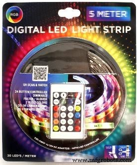
Although nowhere specified on the package or on the LED strip itself, soon I found out that this was as a type of strip with segments of three 5050 LEDs with one WS2811 driver per 3 LEDs.
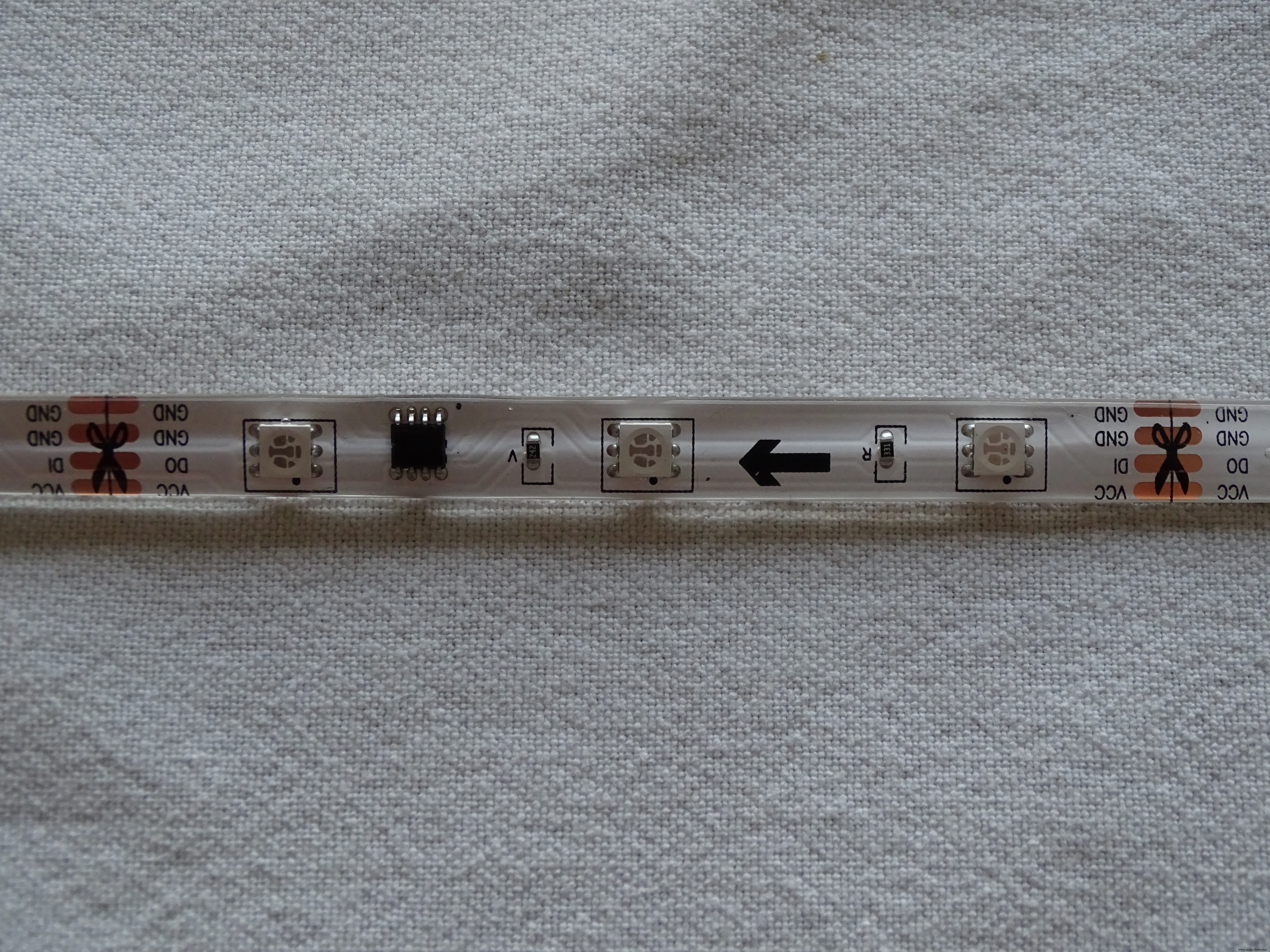
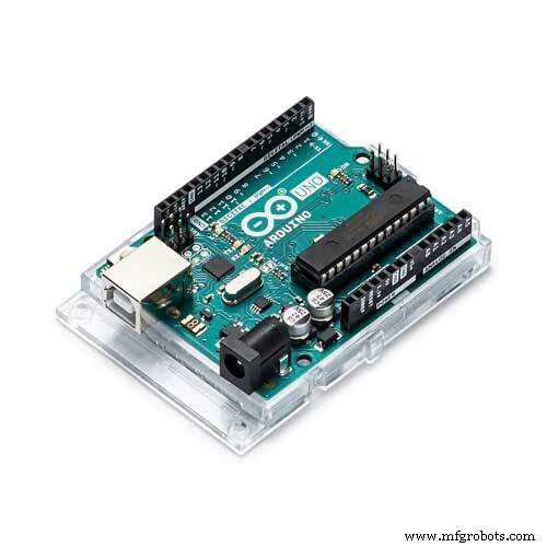
I connected the strip to an Arduino Uno to experiment with it using the Adafruit NeoPixel library and some example code such as RGBW strandtest.
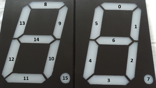
I started to do some brainstorming and came to the idea of using these trips for making an A4-size 7-segment display. Seven sections of strip as shown above would do the job plus one extra for the Decimal Point on the display. This is making it effectively 8 segments that would be controlled from just one output Pin of the Arduino and powered with the 12 V adaptor already contained in the ACTION package.
But what can you do with just one 7-segment Display?
I decided to make 2 of them and use them for creating a Bingo Machine displaying random numbers between 1 and 75 after the push of a button.
Step 1: Making the 7-Segment Displays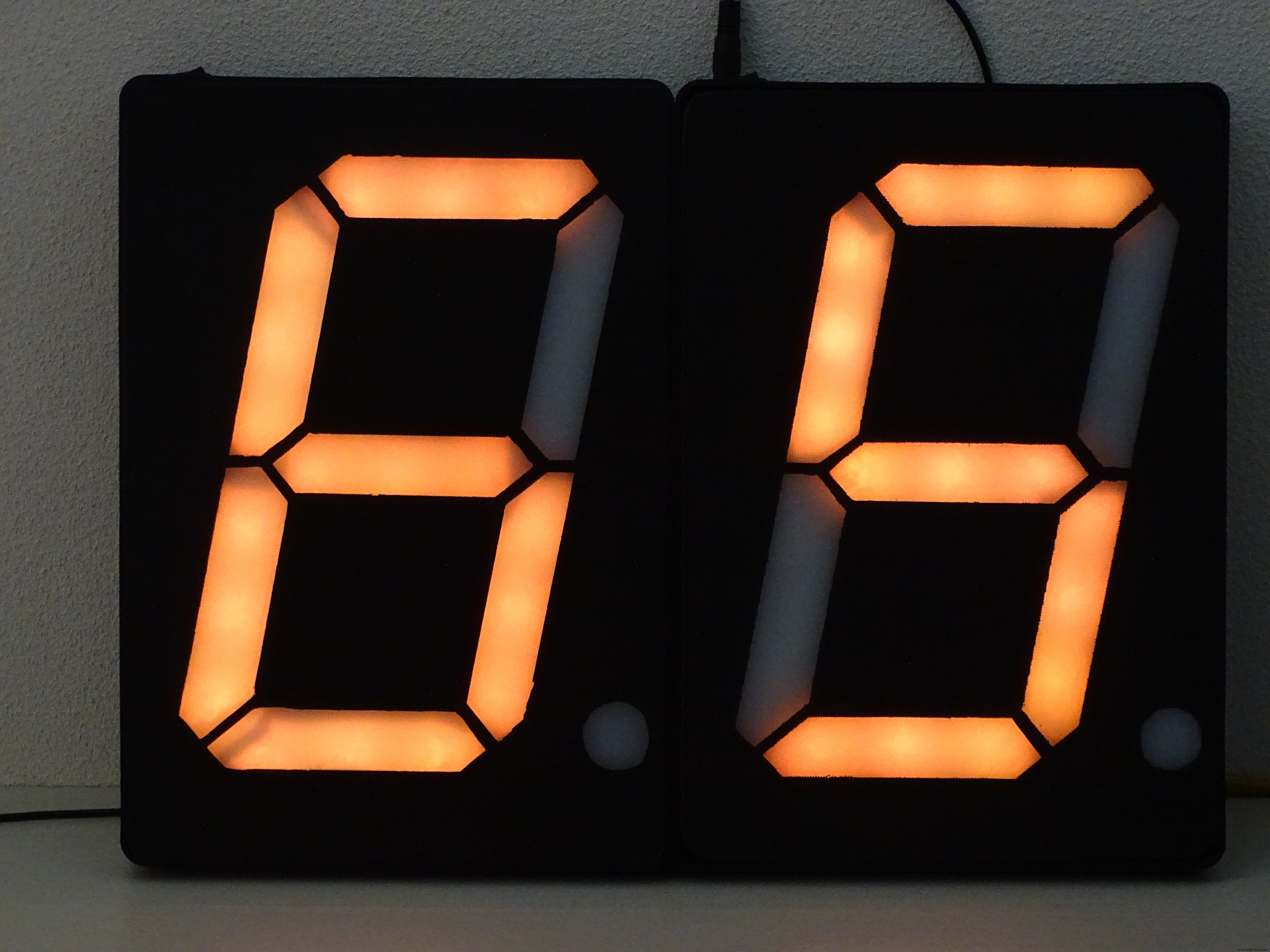
The whole making process of the displays, is a pretty long story, which I could describe in a separate Tutorial. The short version of the making is as follows:
Both A4-size displays were made with conventional means and materials. When using laser cutters and 3D printers the whole process would be different and perhaps simpler. You find pretty good examples on the internet, e.g. YouTube (https://learn.adafruit.com/ninja-timer-giant-7-segment-display/overview) and you can even buy them ready made.
I found it a challenge and fun to make them myself..
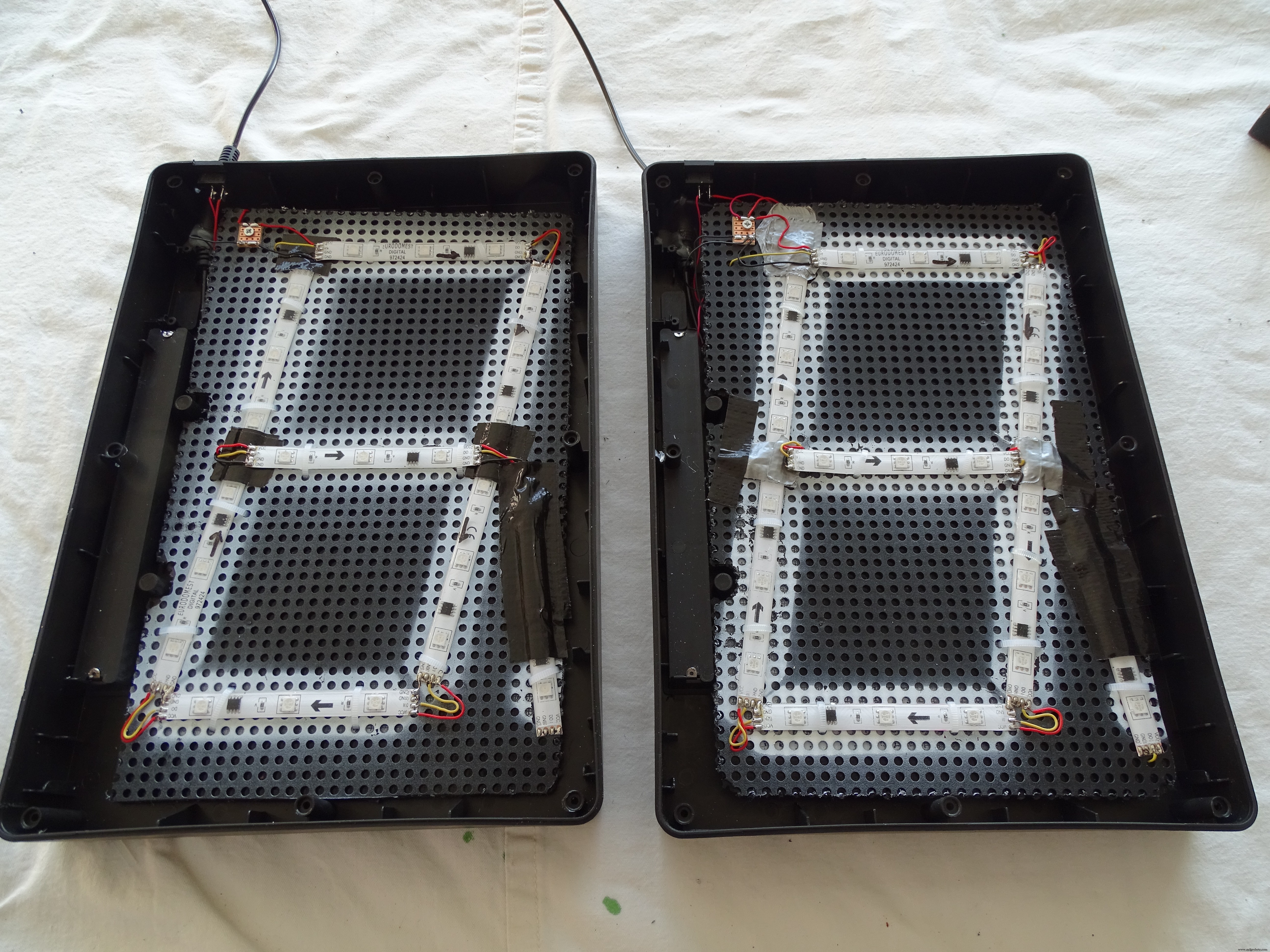
For the LED strips I used 16 sections of 3 LEDS each cut from the WS2811 LED strip from ACTION.
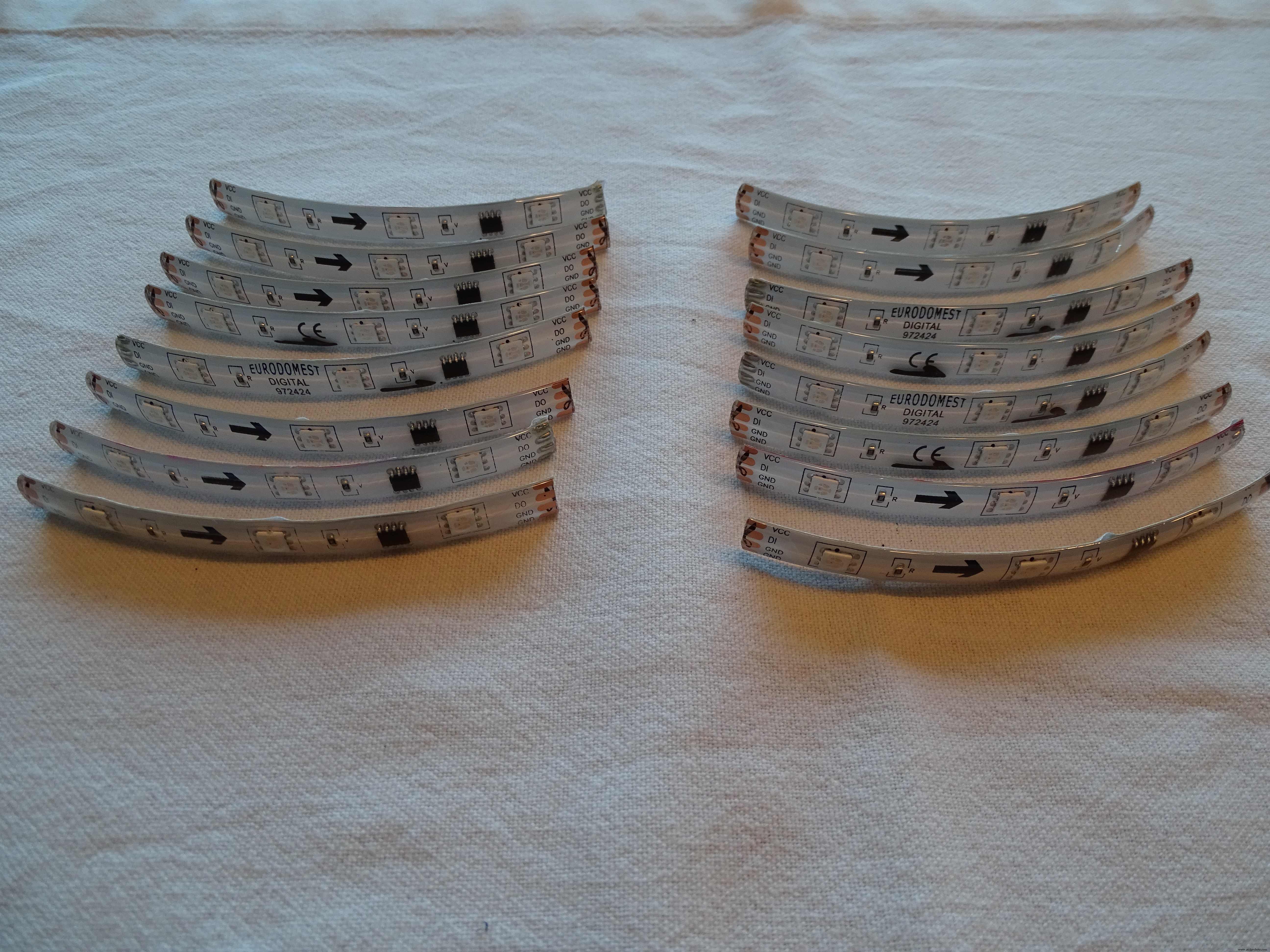
These segments are connected by soldering wires to the +12V, GND and Do and Di of the strips. you can find lots of tutorials on the internet on how to do this properly.
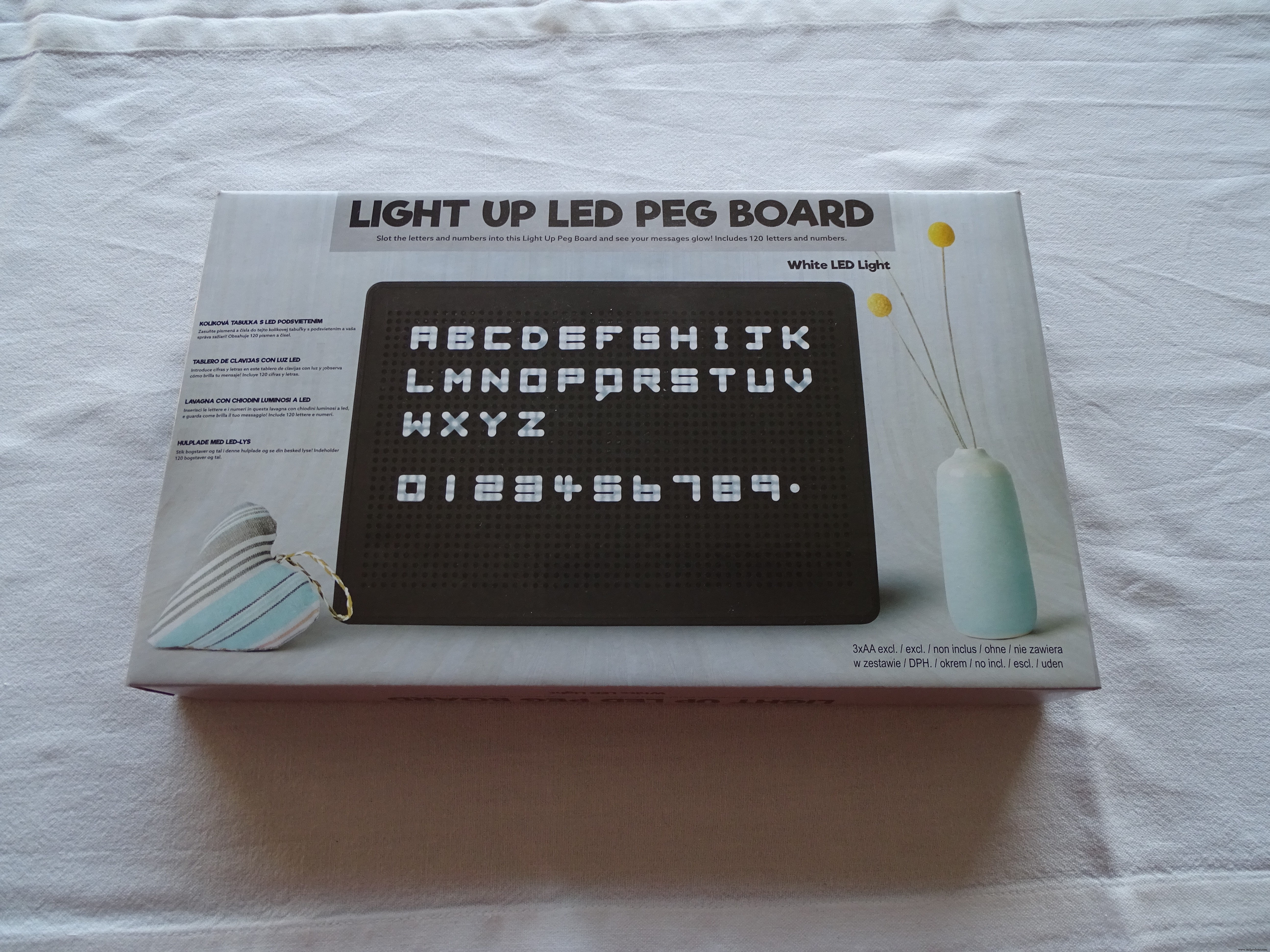
For the housing I used a readily available and affordable Peg Board from the local ACTION store.
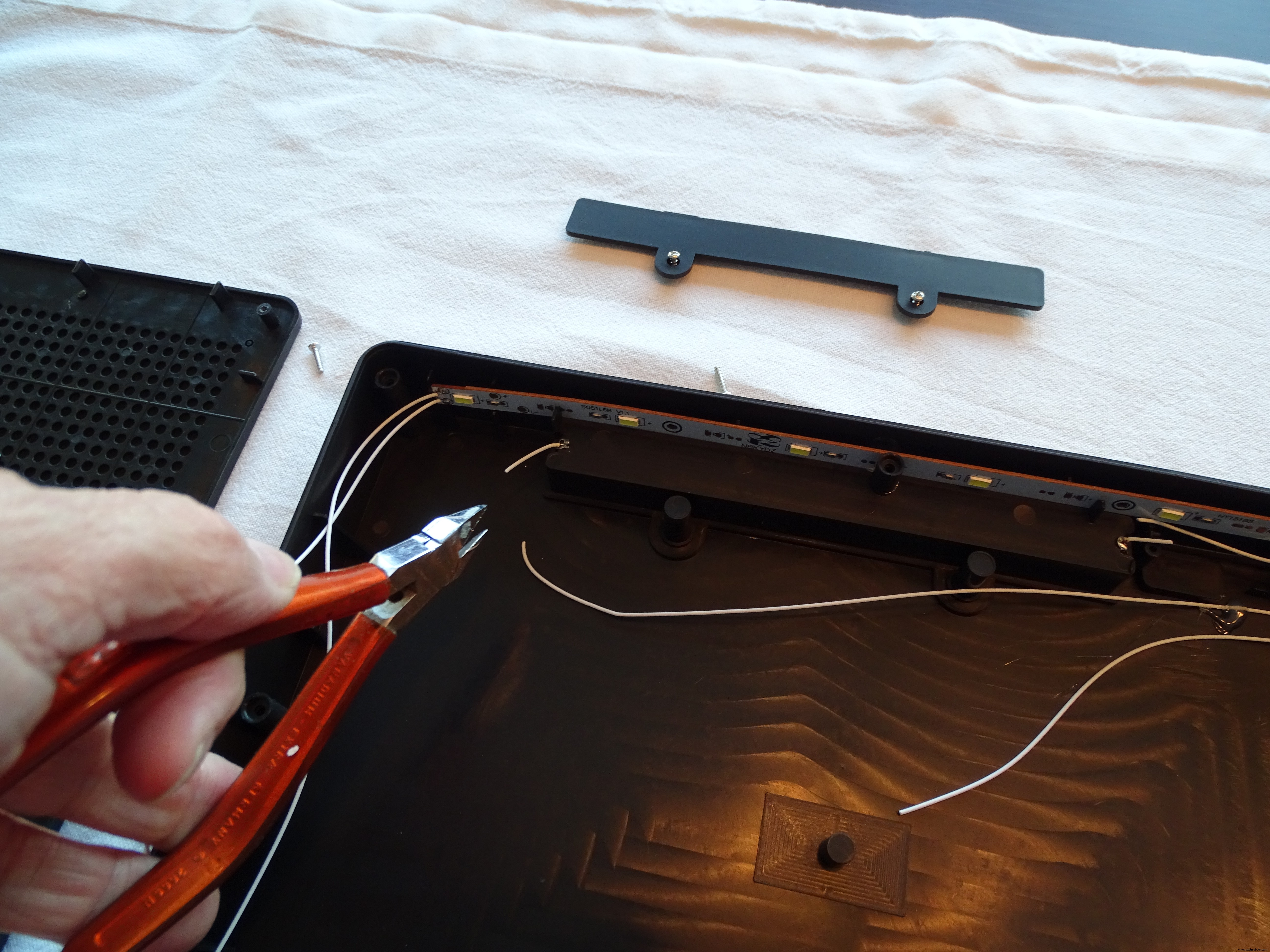
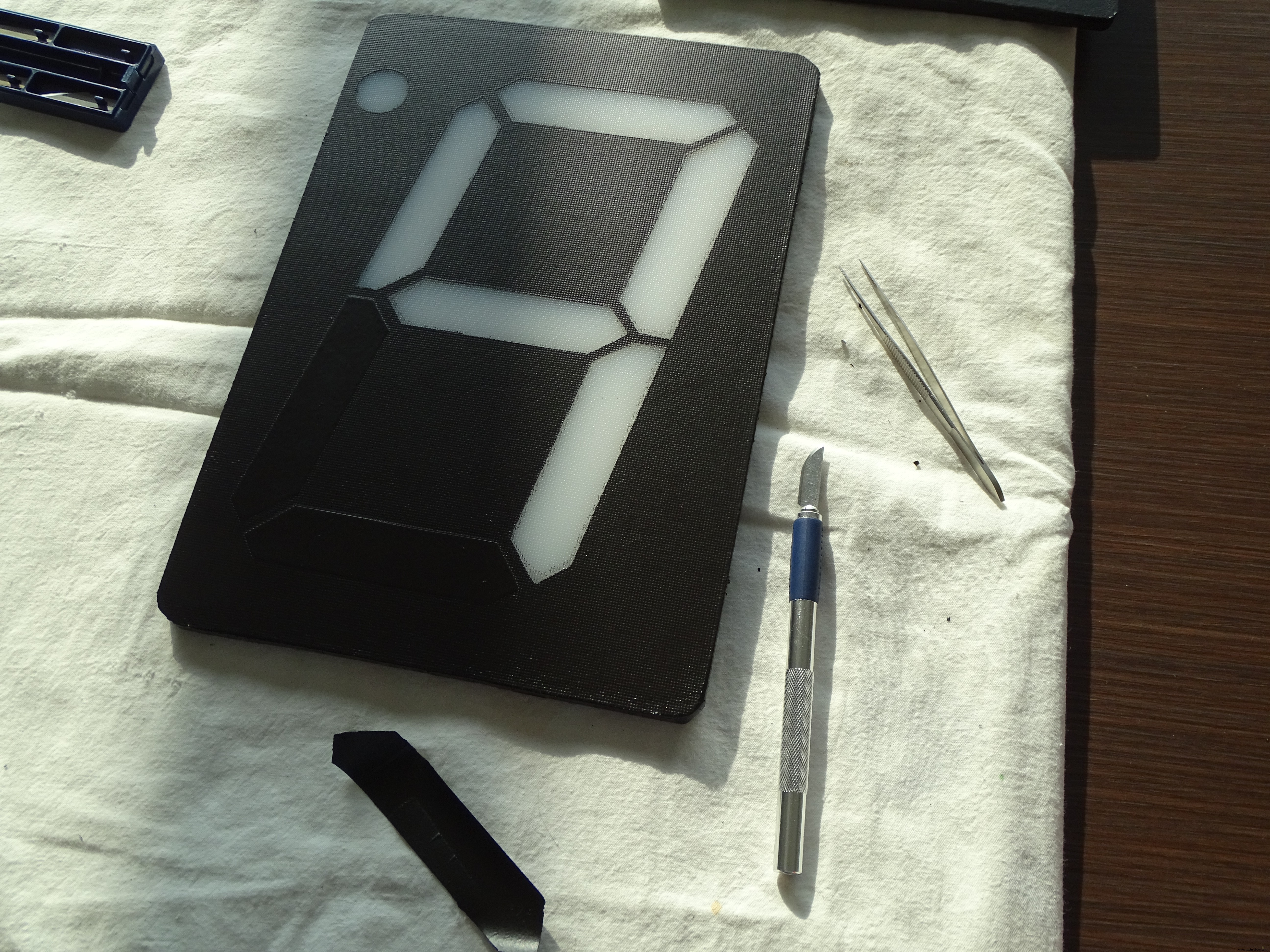
The new fronts of the housing were made of white translucent cutting board material from IKEA.
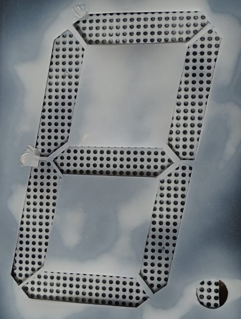
A template was used to cut the segments out of a painted layer on top of the boards (black primer).
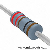
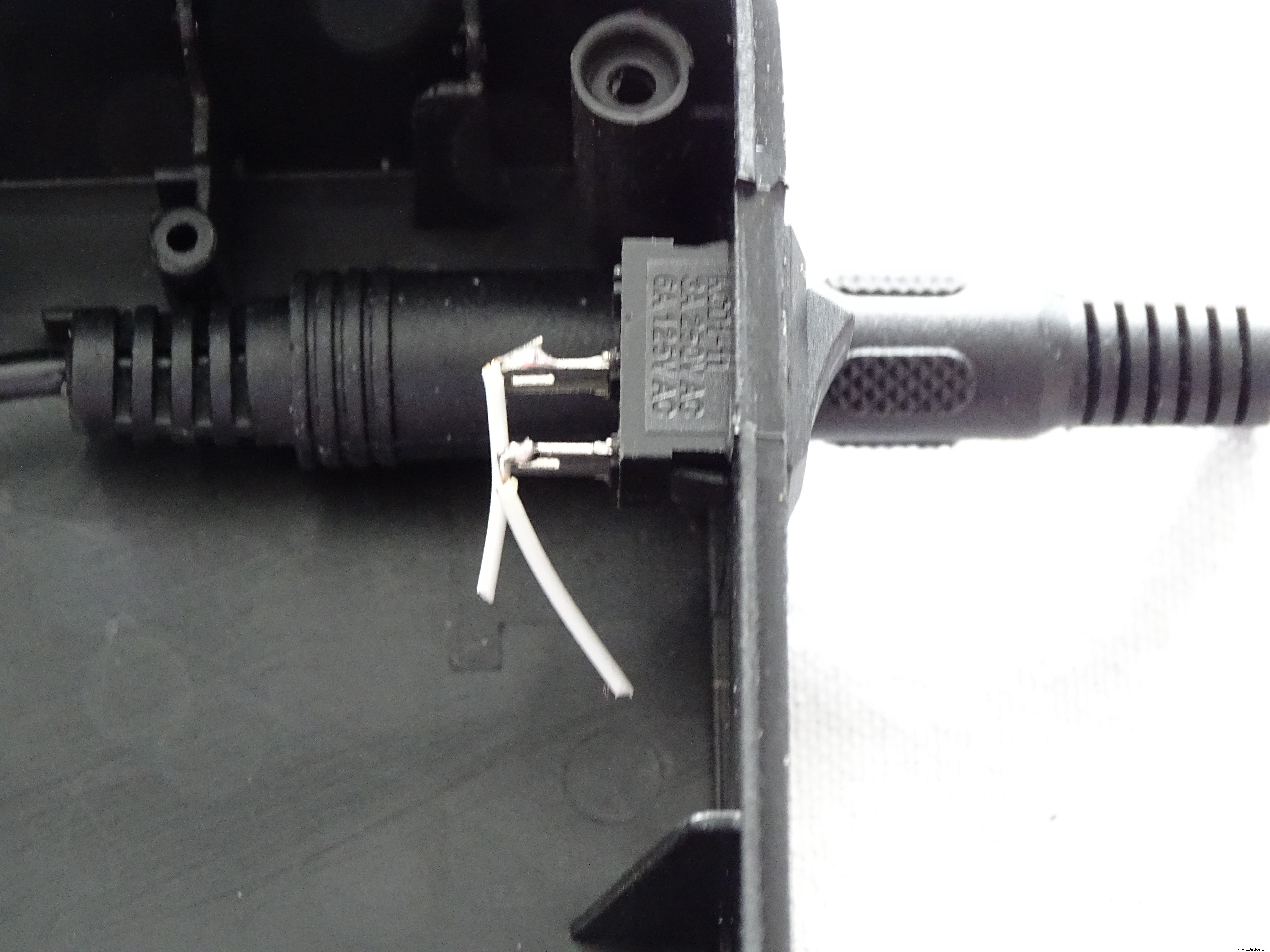
A cheap audio cable (also from ACTION) was used to connect the 7_segment displays with just 3 wires (12V, GND and Data in) to the Arduino via a 220Ohm resistor.

I modified the housing to enable easy plugging-in of the audio connector.
I also decided to create a scoreboard display that would show the generated random numbers, a push button for generating a new number and a "bingo button" for ending and initiating a new round.
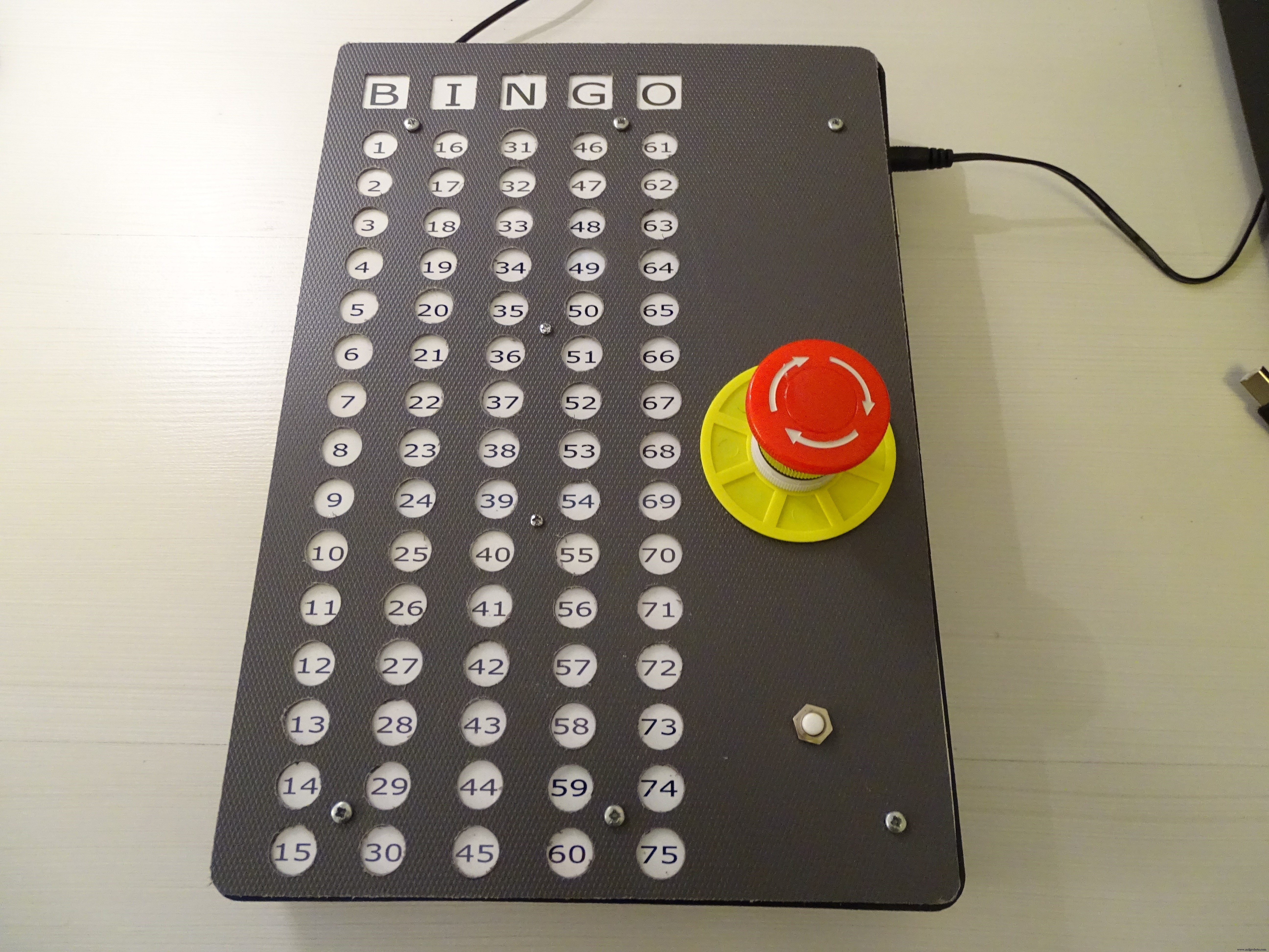
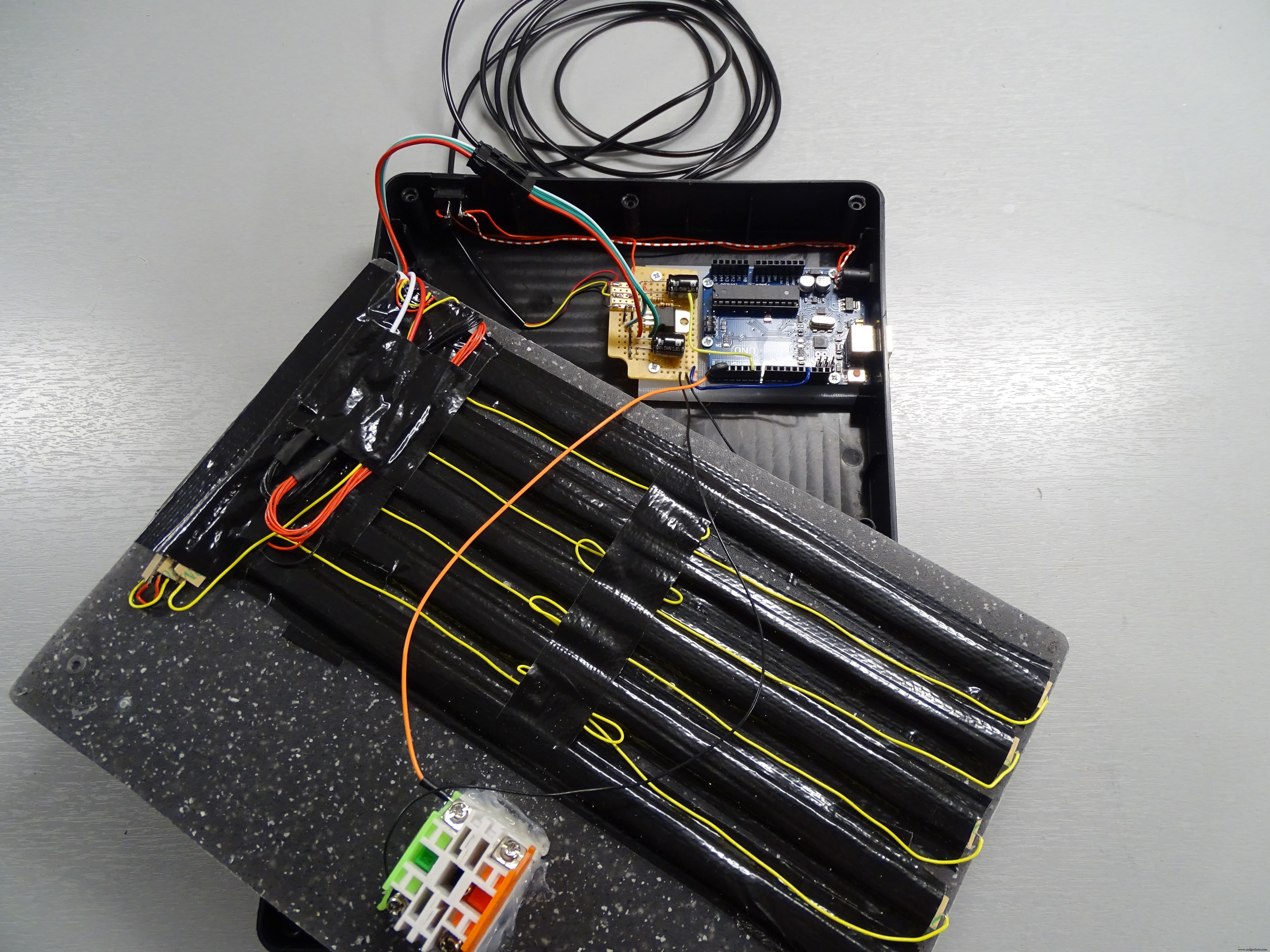
The scoreboard is made using the same ACTION peg board as a housing (described above). The cover plate is made from a dark grey cutting board (again from ACTION) with holes drilled as can be seen above. The top cover is made from an IKEA cutting board. In between the 2 layers is a print on photo paper and a protective transparant foil.
Inside, taped against the back of the cutting board are 5 sections of 15 WS2812 LEDs each plus 3 * 8 LED strip sections for backlighting the word "BINGO."
The initial experiments with the coding and playing with the LED strip and 7-Segment displays were done using an Arduino and a solderless breadboard.
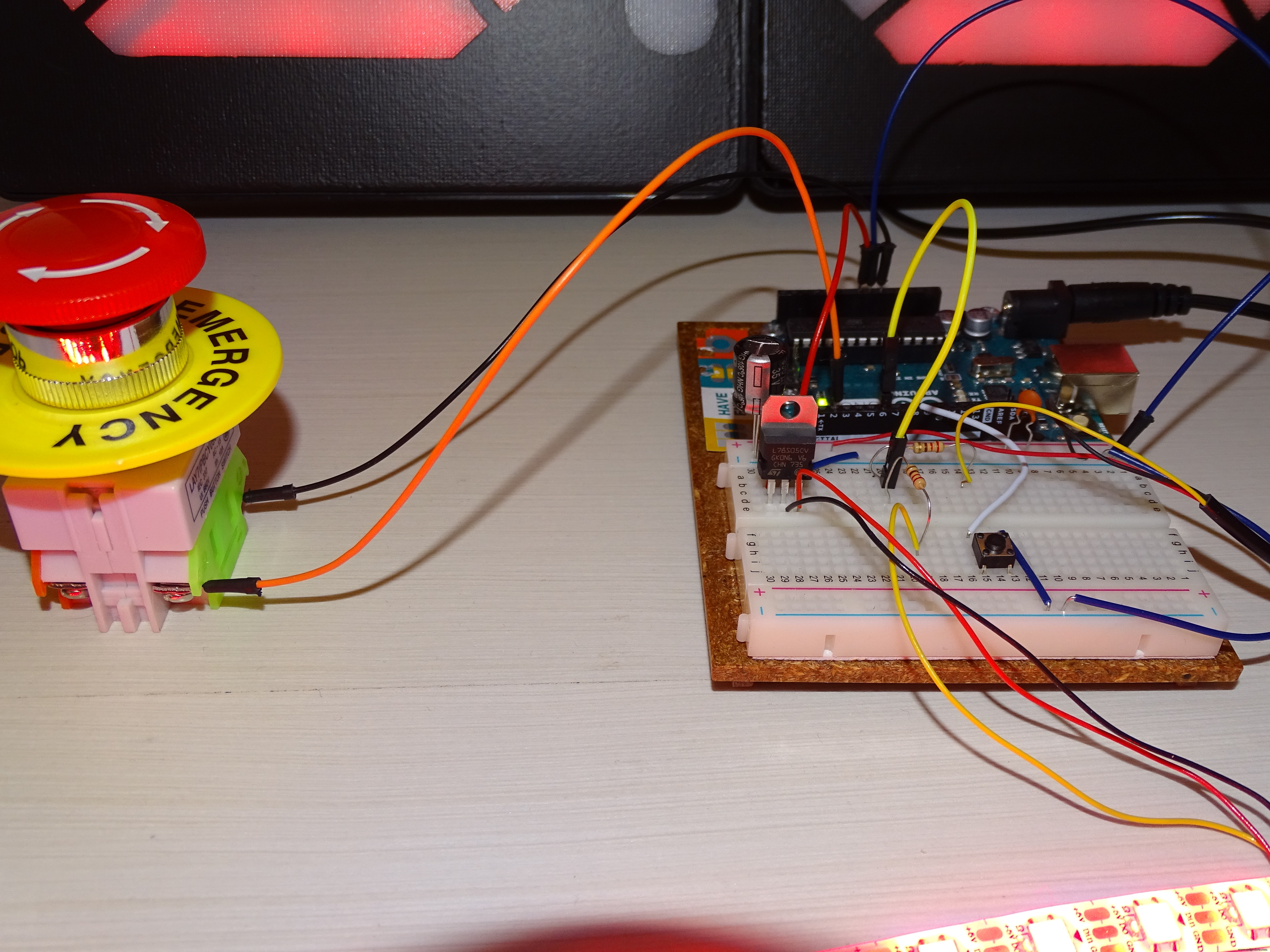
A large momentary push button is connected to GND and to digital IO pin 2 of the Uno. Pushing the button starts the generation of a new random number. After a short "Light Show 1" the random number is shown on the two 7-segment displays.
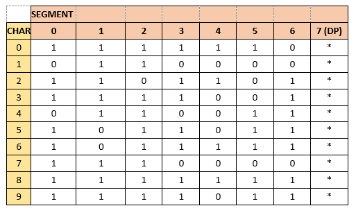
The table used for creating numbers on the 7-segment displays is as follows:
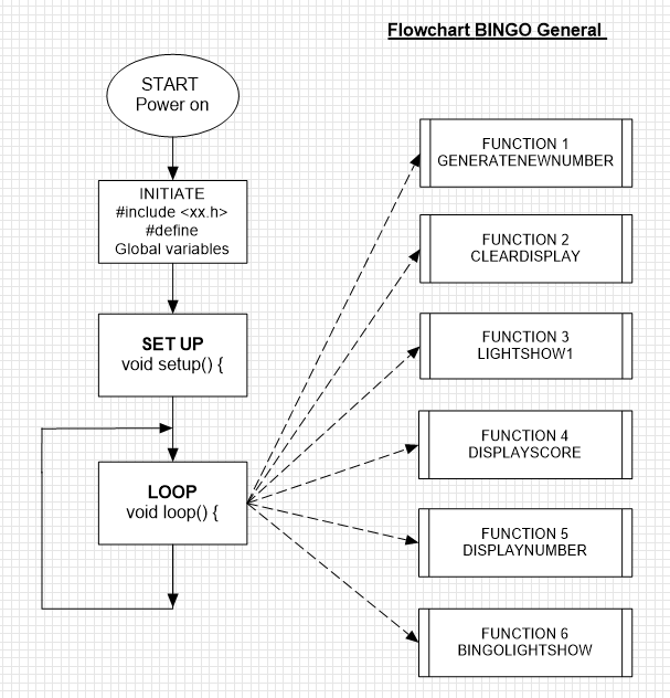
In order to help structuring the Arduino Sketch, I made some simple flow charts with the aid of ClickCharts a free version for non-commercial use (works fine once you get used to some inherent limitations)
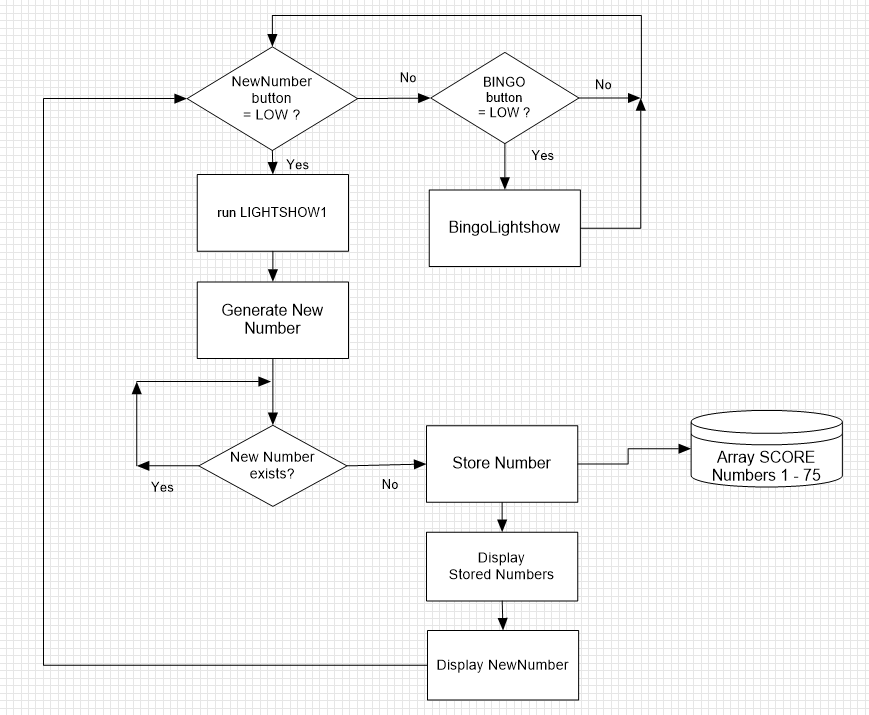
The generated number is stored in an array called SCORE[] consisting of 75 positions either filled with "0" or "1." If the generated new number already exists, automatically a new random number is generated.
The new number is lit on the scoreboard (with 75 numbers) and at the same time the new number is shown on the 7-Segment displays
The scoreboard keeps showing all the random numbers generated until a valid Bingo is achieved. A push button called "BINGO" will end the round with a short "BingoLightShow"
Hereafter the SCORE array is cleared and a new round can be started.
A New Round can also be started by toggling the power switch (disconnecting the 12V power) which will RESET the Arduino and restart the programme.
Step 4: The ElectronicsA 12V, 2A charger supplies the power to the complete Bingo Machine.
The 12V input on the Arduino power jack has been modified to enable power switching (on - off).
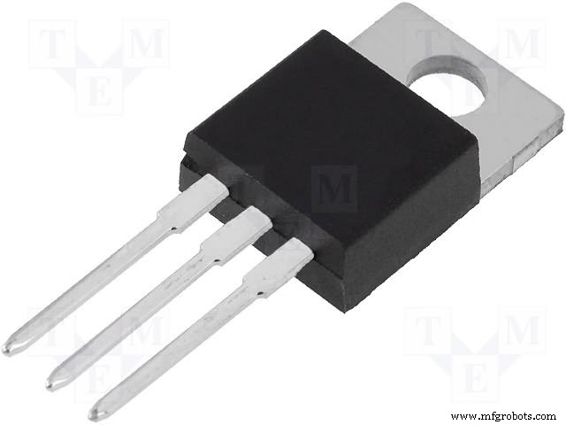
The 5 V power for the 99 LEDs (75 + 24) used for the scoreboard is derived from the 12V input power by means of a 7805 voltage regulator (which can nearly handle the current drawn by the WS2812 LED strip); installing a Heatsink or a power version is recommended (in an update I will probably add a power transistor to deal with the required 5V power mainly consumed by the 99 WS2812 LEDs inside the scoreboard. I have made the sketch for the Arduino in such a way that the power demand of the scoreboard is moderate.
The layout in a Fritzing diagram looks as follows:
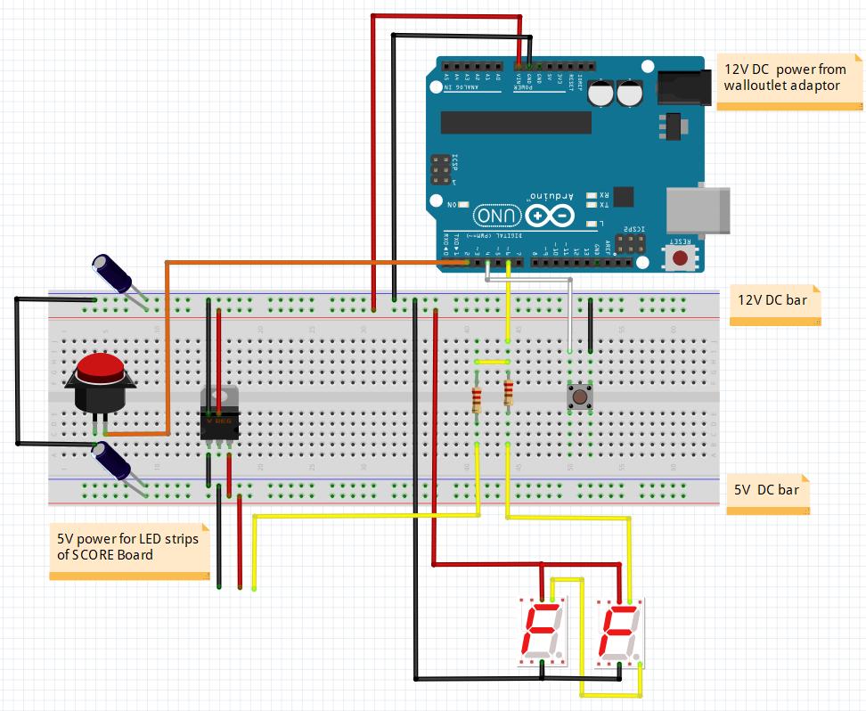
Note that both the 7-segment LED sections (12V) as well as the LED strips illuminating the numbers 1 -75 on the Bingo scoreboard are controlled by one and the same output pin (6) from the Uno.
Developed and produced by Pierre Pennings (November 2018).
Code
- BINGO_Machine_rev04.ino
BINGO_Machine_rev04.inoArduino
Sketch for BINGO Machine with Arduino Uno and 2 A4 sized 7-Segment Displays with an Electronic Score Board/*
This is the code for a Bingo Machine developed and produced by Pierre Pennings (November 2018)
The machine uses 2 DIGIT large A4 sized 7-Segment displays made with WS2811 LED strip powered with 12V (pairs of 3 LEDs with 1 control chip)
Each segment consisting of 3 LEDs is adressed with just one control adress
Each display has 7 segments plus a decimal point (DP)
The numbers presented on the 2 displays run from 1 to 75, just like in a normal BINGO game
A momentary push button is connected to GND and to digital IO pin 6 of an ARDUINO UNO
Pushing the button starts the generation of a New random Number
After a short "Light Show 1" the random number is shown on the two 7-Segment displays
The generated Number is also stored in an Array called SCORE[] consisting of 75 positions either filled with "0" or "1"
If the generated New Number allready exist, automatically a new random number is generated
All electronics including the ARDUINO UNO itself have been built in a separate Score Board Display
The 75 numbers are lit with one WS2812B controller chips with one SMD5050 LED each (powered with 5 V)
The Score Board shows all the random numbers generated until a valid BINGO is achieved
A push button called "BINGO" will end the round with a short "BingoLightShow"
Hereafter the SCORE array is cleared and a new round can be started
A New Round can also be started by toggeling the power switch (disconnecting the 12V power) which will RESET the ARDUINO and restart the programme
A 12V, 2A charger supplies the power to the complete BINGO machine
The 12 V input on the ARDUINO power jack has been modified to enable power switching (on - off)
The 5 V power for the 99 LEDs (75 + 24) used for the Score Board is derived from the 12V input power by means of a 7805 voltage regulator
(which can nearly handle the current drawn by the WS2812 LED strip); installing a Heatsink or a power version is recommended
This code is licensed under GPL3+ license.
*/
#include <Adafruit_NeoPixel.h>
const int NewnumberButton = 2 ; // Digital IO pin 2 is connected to the Newnumber button with a normally open contact
// Pin 2 will be driven with the built-in pull-up resistor to make it normally HIGH
// The switch will pull the pin to ground momentarily.
// On a high -> low transition by pushing the button the programme will generate a New Number.
const int BingoButton = 4 ; // Digital IO pin 4 is connected to the BINGO button with a normally open contact
// Pin 4 will be driven with the built-in pull-up resistor to make it normally HIGH
// The BINGO Button will pull the pin to ground
// On a high -> low transition by pushing the BINGO button a Lightshow will start and thereafter the programme will end.
const int LedPin = 6 ; // Digital IO pin 6 connected to the Data In (DI) of the WS 2811 LED strips via a 220 Ohm resistor
int Newnumber = 1;
int Bingo = 1;
int SCORE[76];
int count = 0;
long randNumber;
int NUMBER = 0;
int NW_NUMBER = 0;
int TENSNUMBER = 0;
int UNITNUMBER = 0;
#define NUM_LEDS 99 // the first 16 are used to control (WS 2811) the LED's in the 2 digit 7-segment displays
//(two times 8 segments on the two displays); number 0 -7 are for the UNIT number
// Number 8 - 15 are for the TENS number ( number 7 and 15 are the DPs of each DIGIT)
// for displaying the numbers on the Score Board Display and controlling the (WS2812) LEDS the adresses 16 upto 99 are used
// 24 LEDs are used for backlighting the letters BINGO and 75 for the score board to enable the display of the generated BINGO numbers;
// all of the LEDs will be controlled with just one wire! from LED_PIN 6
// as a matter of fact two different types of LED strip are controlled (in parralel)from the same LedPin 6 via two 220 Ohm resistors
#define BRIGHTNESS 250 // sets the brightness of the LEDs to allmost maximum (255)
Adafruit_NeoPixel strip = Adafruit_NeoPixel(NUM_LEDS, LedPin, NEO_GRB + NEO_KHZ800);
/*2-dimensional array with NUMBER to segment allocations, each NUMBER has its own colum----------------------------------------------------
8 0
13 9 5 1
14 6
12 10 4 2
11 15 3 7
Digit 2 Digit 1
Tens Units
7 and 15 represent the Decimal Points (DP)
*/
// 0 1 2 3 4 5 6 7 8 9
byte SEGMENTarray [8][10] = { {1,0,1,1,0,1,1,1,1,1,}, //segment 0 or 8
{1,1,1,1,1,0,0,1,1,1,}, //segment 1 or 9
{1,1,0,1,1,1,1,1,1,1,}, //segment 2 or 10
{1,0,1,1,0,1,1,0,1,1,}, //segment 3 or 11
{1,0,1,0,0,0,1,0,1,0,}, //segment 4 or 12
{1,0,0,0,1,1,1,0,1,1,}, //segment 5 or 13
{0,0,1,1,1,1,1,0,1,1,}, //segment 6 or 14
{0,0,0,0,0,0,0,0,0,0,}, //segment 7 or 15
};
byte color_scheme[] = {
50, 100, 200,
100, 150, 250,
150, 200, 50,
200, 250, 100,
250, 50, 150,
0, 100, 200,
50, 150, 250,
100, 200, 0,
150, 250, 50,
200, 0, 100,
250, 50, 200,
0, 100, 250,
50, 150, 0,
250, 0, 0
};
/////////////////////////////////////////////////// the setup code that follows, will run once after "Power On" or after a RESET
void setup() {
Serial.begin(9600);
pinMode(LedPin, OUTPUT); // initialize the LedPin 6 as an output:
pinMode(NewnumberButton, INPUT_PULLUP); // initialize the pushbutton pin 2 as an input:
pinMode(BingoButton, INPUT_PULLUP); // initialize the bingobutton pin 4 as an input:
strip.setBrightness(BRIGHTNESS);
strip.begin(); // Initialize all LEDs to "off"
strip.show();
for (int t = 16; t < 24 ; t++)
{
strip.setPixelColor(t, 0, 0, 250); // After Power On show the word BINGO on the Score Board with Blue characters
strip.show(); // note that the order of colors of the WS2812 LED strip is R,G,B
}
for (count = 0; count < 76 ; count++) { // put all data in the Array SCORE to 0 (Array positions run from 0 to 75; the zero position is not used)
SCORE[count] = 0;
}
/*for (int n = 0; n < 10 ; n++) // this code can be used for testing all the numbers from 0 - 9 on the two 7-Segment displays (the 2 DP's are not tested)
{
for (int s = 0; s < 8 ; s++)
{
int z = SEGMENTarray [s][n];
int i = 0 + s; int j = 8 + s;
strip.setPixelColor(i, z*250, 0, z*50);
strip.setPixelColor(j, z*250, 0, z*50);
strip.show();
Serial.print("["); Serial.print(n); Serial.print("]"); Serial.print("["); Serial.print(s); Serial.print("] = ");Serial.print(z); Serial.print(" ");
}
delay (1500);
Serial.println();
}
*/
}
/////////////////////////////////////////////////// the loop code that follows, will run repeatedly until "Power Off" or a RESET
void loop() {
Newnumber = digitalRead(NewnumberButton);
if (Newnumber == LOW) // no need for a Short delay to eliminate bouncing effects of the button because at first LOW the loop proceeds
{
randomSeed(millis());
do {
GENERATENEWNUMBER (75); // generate a NW_NUMBER between in the range from 1 to 75
} // if the NW_NUMBER allready exists: generate again a NW_NUMBER
while (NW_NUMBER == SCORE[NW_NUMBER] * NW_NUMBER);
SCORE[NW_NUMBER] = 1; // put a 1 in the Array at the NW_NUMBER position
NUMBER = NW_NUMBER;
TENSNUMBER = int (NUMBER / 10); // calculate the decimal value of the NW_NUMBER and the unit value
UNITNUMBER = NW_NUMBER - (10 * TENSNUMBER);
CLEARDISPLAY ();
LIGHTSHOW1 (4, 100); // start lightshow1
CLEARDISPLAY ();
//PRINTNUMBERSERIAL(); // print the generated NW_NUMBER to the serial monitor and show the new content of the SCORE array
DISPLAYNUMBER (TENSNUMBER, UNITNUMBER);
DISPLAYSCORE ();
}
else {
Bingo = digitalRead(BingoButton);
if (Bingo == LOW)
delay (3000); // a delay of 3 second to eliminate bouncing effects and accidental pushing of the button because
if (Bingo == LOW)
{
BINGOLIGHTSHOW ();
for (count = 0; count < 76 ; count++) // put all data in the Array SCORE back to 0 and a new BINGO round can be started
{
SCORE[count] = 0;
}
}
}
}
//////////////////END of LOOP////////////////////////////////////////////////////////////
/////////////////////////////////////////////////// Hereafter follow the specific Functions that are called from within the loop
void LIGHTSHOW1 (int duration, uint8_t wait) {
for (int t = 16; t < 24 ; t++)
{
strip.setPixelColor(t, 0, 0, 0); // turn off the BINGO Leds with Blue characters as put upon set up
strip.show();
}
for (int k = 0; k < duration; k++)
{ // flash the DP leds in a white color
strip.setPixelColor(7, 200, 200, 200);
strip.show();
delay(wait);
strip.setPixelColor(7, 0, 0, 0);
strip.setPixelColor(15, 200, 200, 200);
strip.show();
delay(wait);
strip.setPixelColor(15, 0, 0, 0);
}
int redVal, blueVal, greenVal;
for (int k = 1; k < 45 ; k = k + 3)
{ // run a rainbow color lightshow with colors defined in the Array color_scheme
redVal = color_scheme[k];
blueVal = color_scheme[k + 1];
greenVal = color_scheme[k + 2];
for (int p = 0; p < 7; p++)
{ // the collors of the WS2811 strip are adressed in the order R, B, G
int i = 0 + p; int j = 8 + p;
strip.setPixelColor(i, strip.Color(redVal, blueVal, greenVal) );
strip.setPixelColor(j, strip.Color(greenVal, redVal, blueVal ) );
strip.show();
delay(30);
}
}
for (int q = 0; q < 7 ; q++)
{ // put all segments of the 7-segment displays to "off"
int i = 0 + q; int j = 8 + q;
strip.setPixelColor(i, 0, 0, 0);
strip.setPixelColor(j, 0, 0, 0);
strip.show();
}
}
/////////////////////////////////////////////////Hereafter follows the function for generating the BINGO LIGHTSHOW after the Bingo Button is pushed
void BINGOLIGHTSHOW () {
for (int l = 0; l<10; l++)
{
for (int k = 24; k < 39 ; k++) // present a waterfall of white leds on the SCORE board
{
strip.setPixelColor(k, 200, 200, 200);
strip.setPixelColor(k+15, 200, 200, 200);
strip.setPixelColor(k+30, 200, 200, 200);
strip.setPixelColor(k+45, 200, 200, 200);
strip.setPixelColor(k+60, 200, 200, 200);
strip.show();
delay(5);
strip.setPixelColor(k, 0, 0, 0);
strip.setPixelColor(k+15, 0, 0, 0);
strip.setPixelColor(k+30, 0, 0, 0);
strip.setPixelColor(k+45, 0, 0, 0);
strip.setPixelColor(k+60, 0, 0, 0);
strip.show();
}
for (int t = 0; t < 24 ; t++)
{
strip.setPixelColor(t, 0, 250, 250); // turn on the 7-segment displays and BINGO Leds
strip.show();
}
delay(50);
for (int t = 0; t < 24 ; t++)
{
strip.setPixelColor(t, 0, 0, 0); // turn off the 7-segment displays and BINGO Leds
strip.show();
}
}
}
/////////////////////////////////////////////////// Hereafter follows the function for generating a new number after the New Number Button is pushed
void GENERATENEWNUMBER (int range) {
randNumber = random(1, range + 1);
NW_NUMBER = int(randNumber);
}
/*
////////////////////////////////////////////////// This function can be used to present the generated NUMBER and show the modified contents of the SCORE array
void PRINTNUMBERSERIAL () {
Serial.print("NUMBER = ");
Serial.print(NUMBER);
Serial.print(" , TENSNUMBER = ");
Serial.print(TENSNUMBER);
Serial.print(" , UNITNUMBER = ");
Serial.println(UNITNUMBER);
count = 1;
while (count < 76)
{ // print all data in the Array SCORE (Array positions from 0 to 75; the zero position remains 0)
for (int column = 0; column < 15; column++)
{
Serial.print("["); Serial.print(count); Serial.print("] = "); Serial.print(SCORE[count]); Serial.print(" ");
count++;
}
Serial.println("");
}
}
*/
///////////////////////////////////////////////// This function is used to display the generated NUMBER on the two 7-Segments displays
void DISPLAYNUMBER (int TENS, int UNIT) {
for (int t = 16; t < 24 ; t++)
{
strip.setPixelColor(t, 200, 0, 0); // turn on the BINGO word Leds in RED characters
strip.show();
}
for (int s = 0; s < 8 ; s++)
{ // take the data from the SEGMENT array to turn on correct segments for displaying the UNITS and TENS of the NUMBER in RED
int t = SEGMENTarray [s][TENS];
int u = SEGMENTarray [s][UNIT];
int i = 0 + s; int j = 8 + s;
strip.setPixelColor(i, u*250, 0, 0);
if (TENS!=0) {
strip.setPixelColor(j, t*250, 0, 0);
}
else {
strip.setPixelColor(j, 0, 0, 0);
}
strip.show();
}
}
///////////////////////////////////////////////// This function is used to display the generated NUMBER on the two 7-Segments displays
void DISPLAYSCORE () {
for (int t = 16; t < 24 ; t++)
{
strip.setPixelColor(t, 200, 0, 0); // turn on the BINGO word Leds in RED characters
strip.show();
}
for (int s = 24; s < 100 ; s++)
{ // turn on the LEDs for the existing Numbers in GREEN
int u = SCORE[s-23];
strip.setPixelColor(s, 0, u*200, 0);
strip.show();
}
strip.setPixelColor((23+NUMBER), 200, 0, 0); // turn on the LEDs for the new Number in RED
strip.show();
}
///////////////////////////////////////////////// This function is used to clear the two 7-Segments displays
void CLEARDISPLAY () {
for (int q = 0; q < 7 ; q++)
{
int i = 0 + q; int j = 8 + q;
strip.setPixelColor(i, 0, 0, 0);
strip.setPixelColor(j, 0, 0, 0);
strip.show();
}
for (int t = 16; t < 24 ; t++)
{
strip.setPixelColor(t, 0, 0, 0); // turn off the RED characters of the BINGO word
strip.show();
}
}
Custom parts and enclosures
tekening_gaten_patroon_puntjes_xgW76A8Jmw.svgTo be used as a Template for the fronts of the displays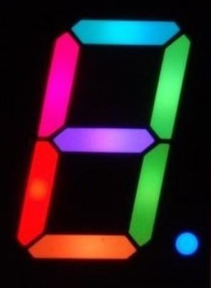
Schematics
bingo_sketch_66WRdQITE2.fzzManufacturing process
- Build Your Own DIY Homework Writing Machine at Home
- Build a Retro Numitron Clock with Arduino: Simple, Reliable, and Energy‑Efficient
- Build a Portable RFID Door Lock with Arduino – Step-by-Step Guide
- Arduino‑Powered Smart Coffee Maker with Bluetooth Control and Temperature Monitoring
- Build a Sensitive Arduino Metal Detector with Ferrous/Nonferrous Discrimination
- DIY Arduino Height Measurement Device – Accurate & Easy to Build
- Build a 7‑Segment Clock with Arduino Nano, DS3231 RTC, and LDR Auto‑Brightness
- Master GRBL: Step‑by‑Step Guide to Setting Up and Controlling Your Arduino‑Powered CNC Machine
- Build a Wire‑Free Arduino Robot Arm, Controlled from Your Smartphone
- Transform Your DIY SCARA Robot into a Precise Laser Engraver with Arduino