


Custom DAW Control Box for Roland E-Drum Racks
Components and supplies
| × | 1 | ||||
| × | 1 | ||||
| × | 1 |
Necessary tools and machines
 |
|
Apps and online services
 |
|
About this project
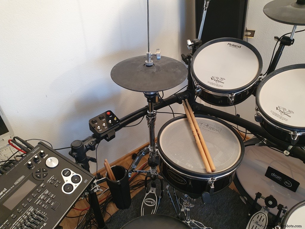
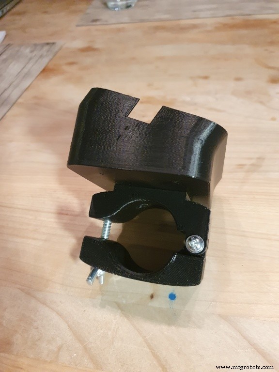
It was inconvenient for me to operate my laptop running a DAW (in my case Cubase) while recording a drum track. So I wanted to have a distraction free method to trigger a few essential commands such as start/stop/record etc without dropping my sticks. The available commerical solutions where too expensive or not practical because e.g. impossible to be mounted to my rack.So I came up with this DIY button-box based on the famous Arduino micro.It can be mounted on standard 38mm tubes used by Roland racks to hold the box.
If you have a 3d printer and would like to built your own remote box, use the instructions below.
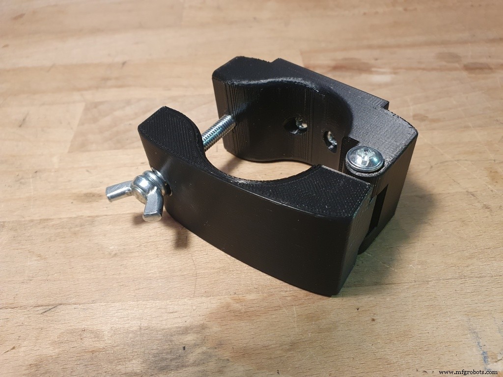
Instructions:1. Print out the 2 rack clamp parts and the box body. PLA will work fine, but if you want more stability use PETG. Combine the clamp by a M4x40 screw as axis between the 2 parts, tighten the screw, but make sure it can still rotate easily.Use a M6 wingscrew and nut as tightener to hold firmly on your rack.Use 2x M3x4 screws (or similar) and nuts for combining the upper clamp part to the box.
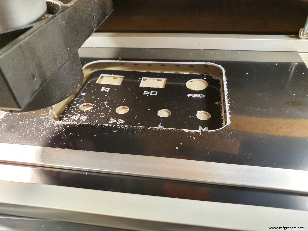
2. For the front-panel you have several choices. You might want to design your own variant depending on your buttons of choice. Use one the available front-panal templates in either stl (for 3d printer) or svg (for CNC) to create your own front-panel.(I decided to make the panel on my DIY CNC machine because I liked the engraved design...but a 3d printed panel will work just fine.)
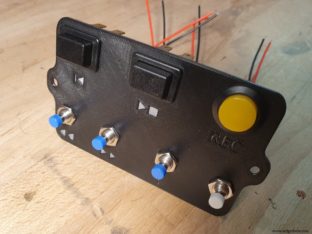
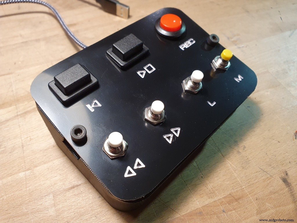
3. After your front-panel is ready, insert the buttons and solder to the correct Arduno ports (see assignment below).I decided to use a seperated PCB to have more space, but that is not mandatory. If you do this, use the 4 holes in the corner to hold the PCB.Finally close and secure the front-panel with 2 M3 screws.
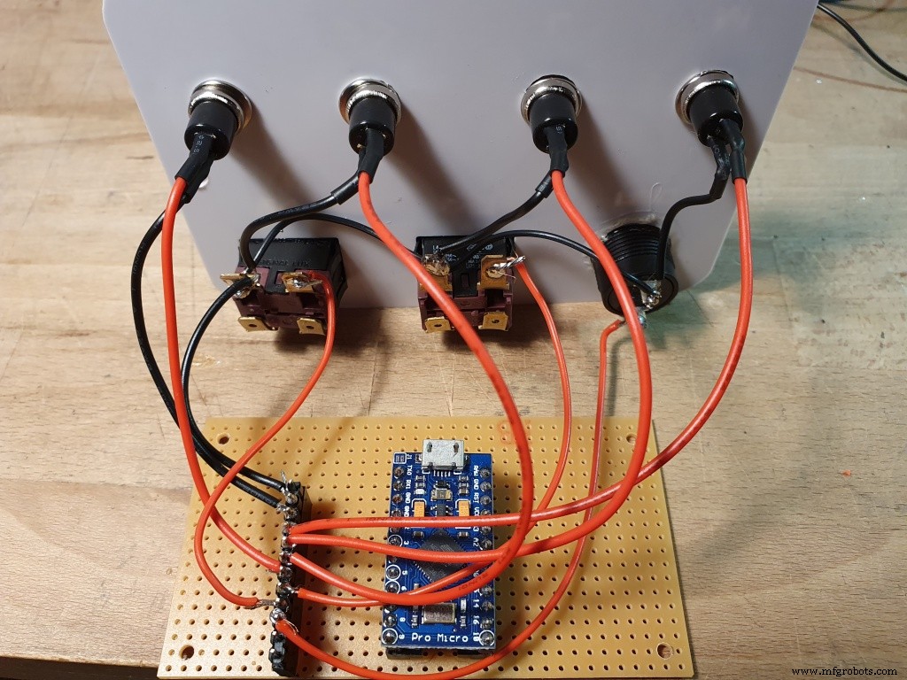
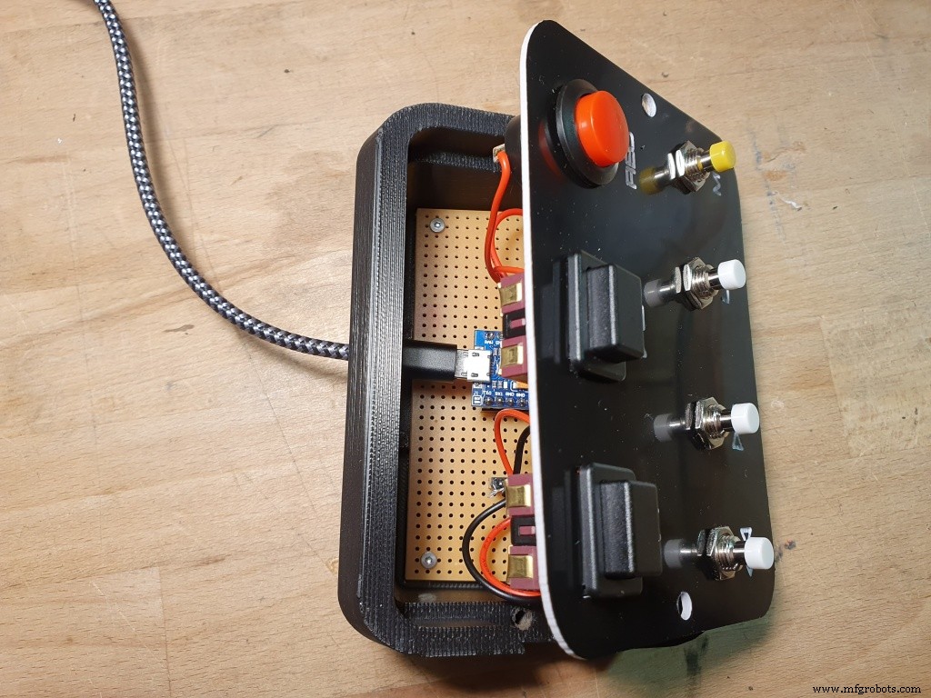
4. Programming the Arduino:Any Micro Pro will do, just make sure it's the Adruino Micro PRO (not the standard Arduino micro!) because of the built-in USB. An Arduino Micro Pro conntected to any PC or laptop can natively emulate a USB keyboard and so can trigger any keystroke, even function keys and num block keys etc. Micro pros are available from different sources, so you might need to modify your code depending on the included libraries. In my case, I decided to use the digial ports 2-8 which will be initalized as internal pull-ups first.The connected push buttons (normally open) will pull the pins to GND which is detected by the code and triggers the programmed action (emulated key press).
For my DAW (Cubase), I decided to use the following setup:
Port Button Key Cubase Function
------------------------------------------
2 M c Metronome On/Off
3 L [Num] 1 Goto Left Locator
4 >> [Num] + Forward
5 << [Num] - Backward
6 P SPACE Play/Stop
7 B b Begin
8 R [Num] * Record
It can be easily changed in the code to match your configuration. Use my enclosed code as example.
Enjoy.
Code
- Arduino Micro Pro Code for Rack Button Box
Arduino Micro Pro Code for Rack Button BoxC/C++
make sure to set the micro pro in your arduino IDE/* ROLAND RACK BUTTON BOX
Note : This is for the Arduino Pro Micro !
Emulates a keyboard to press keys a connected PC for a DAW (here : Steinberg Cubase).
optional : uses emulated UART COM port via USB (for debugging) and LEDs (RX and TX LED) on Micro board
KEYS :
config for Cubase:
https://steinberg.help/cubase_elements_le_ai/v9/de/cubase_nuendo/topics/key_commands/key_commands_default_c.html
Assignment : Arduino Micro Port -> Switch on Button Box -> emulated Key on Keyboard -> Function in Cubase
Port Switch Key Cubase Function
------------------------------------------
2 M c Metronome On
3 L [Num] 1 Goto Left Locator
4 >> [Num] + Forward
5 << [Num] - Backward
6 P SPACE Play/Stop
7 B b Begin
8 R [Num] * Record
mac70
13.01.2021
*/
#define DEBUG_OUTPUT 0 // when defined as 1, an additional serial monitor output will be generated for debugging
#include <Keyboard.h>
// NUM-KEY codes : https://forum.arduino.cc/index.php?topic=659117.0
#define KEYPAD_1 225
#define KEYPAD_PLUS 223
#define KEYPAD_MINUS 222
#define KEYPAD_ASTERIX 221
/*
// in case needed ... other key codes like Shift, Control etc : https://www.arduino.cc/reference/en/language/functions/usb/keyboard/keyboardmodifiers/
char ShiftKey = KEY_LEFT_SHIFT;
char LeftKey = KEY_LEFT_ARROW;
char RightKey = KEY_RIGHT_ARROW;
*/
int RXLED = 17; // The RX LED has a defined Arduino pin
void setup()
{
// buttons are connected to the following digital input pins
// (button normally open, when activated -> pin will be connected to GND)
pinMode(2, INPUT_PULLUP); // Pin 2 is input with internal resistor
pinMode(3, INPUT_PULLUP); // Pin 3 is input with internal resistor
pinMode(4, INPUT_PULLUP); // Pin 4 is input with internal resistor
pinMode(5, INPUT_PULLUP); // Pin 5 is input with internal resistor
pinMode(6, INPUT_PULLUP); // Pin 6 is input with internal resistor
pinMode(7, INPUT_PULLUP); // Pin 7 is input with internal resistor
pinMode(8, INPUT_PULLUP); // Pin 8 is input with internal resistor
pinMode(RXLED, OUTPUT); // Set RX LED as an output
digitalWrite(RXLED, HIGH); // set the RX LED OFF
Keyboard.begin(); // start keyboard emulation
Serial.begin(9600); //This starts the serial monitor
Serial.println("");
if (DEBUG_OUTPUT == 1) Serial.println("Button Box Serial Monitor");
}
void loop()
{
Keyboard.releaseAll();
digitalWrite(RXLED, HIGH); // set the RX LED OFF
delay(50); // short delay
// Process buttons
if (digitalRead(2) == 0) // M
{
if (DEBUG_OUTPUT == 1) Serial.println("Button M"); // Print to the Serial Monitor
digitalWrite(RXLED, LOW); // LED on to signal activity
Keyboard.press('c');
delay(5);
Keyboard.releaseAll();
while(digitalRead(2) == 0); // wait for button to be released
}
if (digitalRead(3) == 0) // L
{
if (DEBUG_OUTPUT == 1) Serial.println("Button L"); // Print to the Serial Monitor
digitalWrite(RXLED, LOW); // LED on to signal activity
Keyboard.press(KEYPAD_1);
delay(5);
Keyboard.releaseAll();
while(digitalRead(3) == 0); // wait for button to be released
}
if (digitalRead(4) == 0) // >>
{
if (DEBUG_OUTPUT == 1) Serial.println("Button >>"); // Print to the Serial Monitor
digitalWrite(RXLED, LOW); // LED on to signal activity
Keyboard.press(KEYPAD_PLUS);
while(digitalRead(4) == 0); // wait for button to be released ... repeat function from PC will re-trigger this key !
Keyboard.releaseAll();
}
if (digitalRead(5) == 0) // <<
{
if (DEBUG_OUTPUT == 1) Serial.println("Button <<"); // Print to the Serial Monitor
digitalWrite(RXLED, LOW); // LED on to signal activity
Keyboard.press(KEYPAD_MINUS);
while(digitalRead(5) == 0); // wait for button to be released ... repeat function from PC will re-trigger this key !
Keyboard.releaseAll();
}
if (digitalRead(6) == 0) // PLAY STOP
{
if (DEBUG_OUTPUT == 1) Serial.println("Button PLAY/STOP"); // Print to the Serial Monitor
digitalWrite(RXLED, LOW); // LED on to signal activity
Keyboard.press(' ');
delay(5);
Keyboard.releaseAll();
while(digitalRead(6) == 0); // wait for button to be released
}
if (digitalRead(7) == 0) // BACK TO START
{
if (DEBUG_OUTPUT == 1) Serial.println("Button BACK"); // Print to the Serial Monitor
digitalWrite(RXLED, LOW); // LED on to signal activity
Keyboard.press('b');
delay(5);
Keyboard.releaseAll();
while(digitalRead(7) == 0); // wait for button to be released
}
if (digitalRead(8) == 0) // REC
{
if (DEBUG_OUTPUT == 1) Serial.println("Button REC"); // Print to the Serial Monitor
digitalWrite(RXLED, LOW); // LED on to signal activity
Keyboard.press(KEYPAD_ASTERIX);
delay(5);
Keyboard.releaseAll();
while(digitalRead(8) == 0); // wait for button to be released
}
}
Custom parts and enclosures
link to my 3D files
in thingiverseCAD file on thingiverse.comManufacturing process
- The Juice Box Revolution: History, Design, and Environmental Impact
- The Button: From Ancient Fastener to Modern Innovation
- DIY Wall‑E Inspired Raspberry Pi CD‑Box Robot
- 5 Proven Packing Hacks to Prevent Shipping Damage
- Custom Mute Button for Microsoft Teams – Simplify Virtual Meetings
- Revolutionary Natural Fiber Crash Box Reduces Motorsport Impact – YCOM & Bcomp’s First of Its Kind
- Optimized Layout and Tracing Guidelines for Box Build Assembly
- Essential Guidelines for Successful Box Build Assembly
- NC Start Button: How It Drives CNC Program Execution
- Custom Shipping Containers: Tailored Solutions for Auto Manufacturers & Suppliers