


Wi‑Fi Controlled FPV Rover Robot with Arduino & ESP8266 – DIY Guide
Components and supplies
 |
| × | 1 | |||
 |
| × | 1 | |||
 |
| × | 1 | |||
| × | 2 | ||||
| × | 1 | ||||
 |
| × | 1 | |||
 |
| × | 1 | |||
 |
| × | 2 | |||
| × | 1 | ||||
| × | 2 | ||||
| × | 1 | ||||
| × | 12 | ||||
| × | 12 | ||||
| × | 8 | ||||
| × | 8 | ||||
| × | 3 | ||||
| × | 6 | ||||
| × | 1 | ||||
| × | 2 | ||||
| × | 1 |
Necessary tools and machines
| ||||
|
Apps and online services
| ||||
 |
| |||
| ||||
 |
| |||
|
About this project
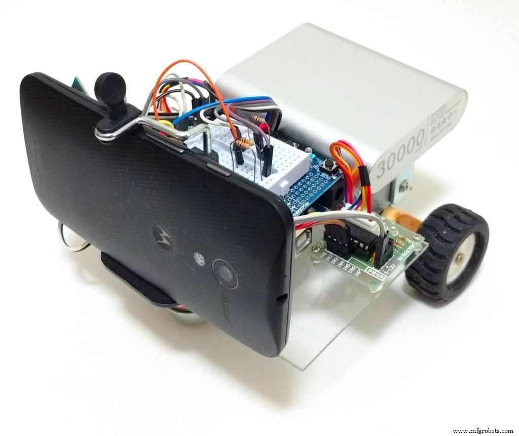
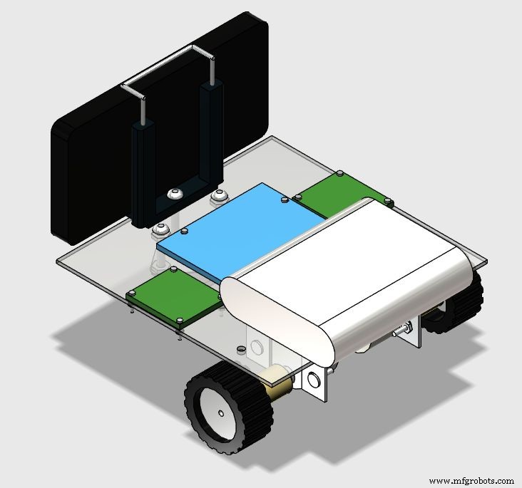
This tutorial shows how to design a remotely controlled two-wheeled robotic rover over a wi-fi network, using an Arduino Uno connected to an ESP8266 Wi-fi module and two stepper motors. The robot can be controlled from an ordinary internet browser, using a HTML designed interface. An Android smartphone is used to broadcast video and audio from the robot to operator's control interface.
There is a lot of robotic kits available online with various shapes, dimensions and prices. But, depending on your application, none of them will fit, and you might find out they are too expensive for your experiments. Or maybe you just want to make your your mechanical structure instead of buying a complete one.This tutorial also shows how to design and build a low-cost acrylic frame for your own robotic project, using just ordinary tools for those who doesn't have access to those expensive 3D printers or laser cutters. A simple robotic platform is presented.
This guide might be adapted to have its shape or control interface changed. It was adapted for other of my robotic projects ("Robô da Alegria"), that you can check in the links bellow:
https://hackaday.io/project/12873-rob-da-alegria-...
https://github.com/ferauche/RoboAlegria
https://hackaday.io/project/12873-rob-da-alegria-...
[Warning: some of the photos are outdated, because the design was further improved. However, the idea presented here is still valid.]
Step 1: Tools
The following tools are needed for the construction of this prototype:
- Hand saw (to perform initial cuts of the acrylic sheet)
- Screewdriver (for bolts and nuts placement)
- Ruler (for dimensions measurement)
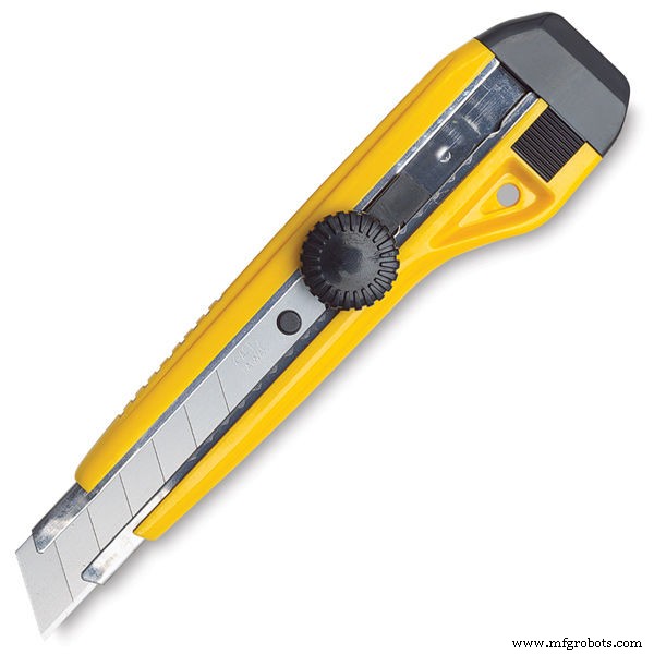
- Utility knife (for cutting the acrylic sheet)
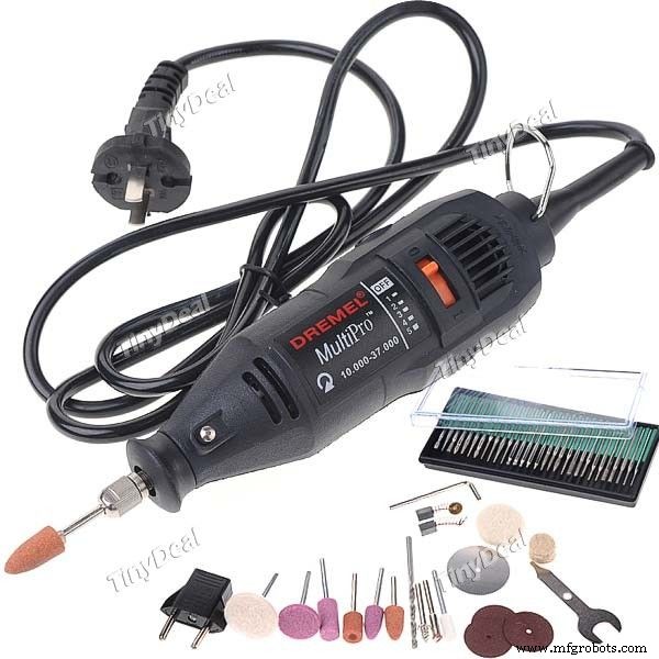
- Drilling machine (to create holes for the bolts)
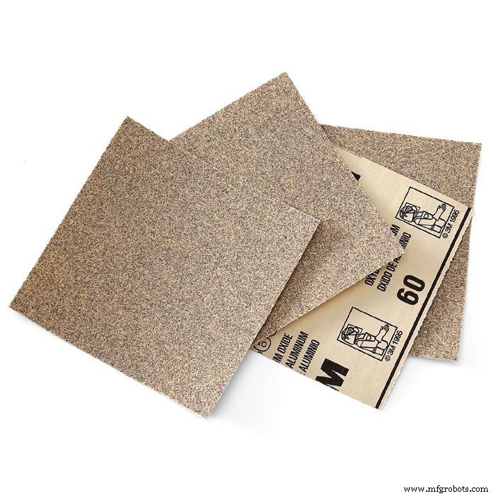
- Sandpaper (to smooth rough edges)
To build a custom robot, first you'll have to design your mechanical structure. It might be easy, depending on your application, or full of details and constraints. You might need to design it in a 3D CAD software or just draw it in 2D, depending on the complexity of your model.
You might also buy the complete structure online if you doesn't want to build your own mechanical structure. There is a lot of robotic kits available online. In this case, you might jump to Step 6.
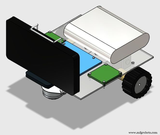
For this tutorial, a low-cost acrylic frame was designed for the attachment of the motors and other components. The structure presented in this tutorial was 3D designed using 123D Design CAD software. Each part was later converted in 2D using Draftsight software.
The following materials were used:
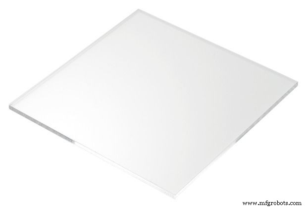
- 2mm acrylic sheet
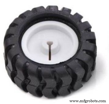
- 42x19mm wheels with rubber tread tire (x2)
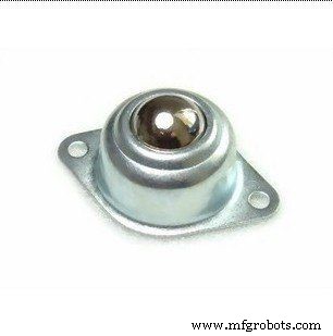
- 49x20x32mm steel ball omni wheel (x1)
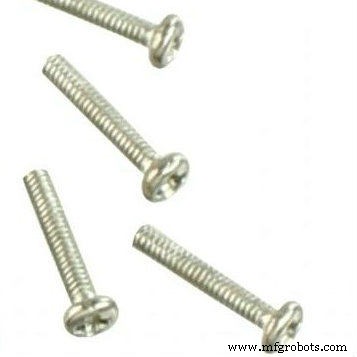
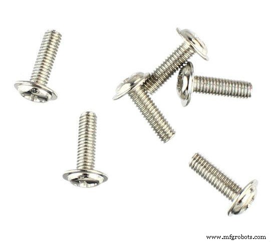
- M2 x 10mm bolts (x12)
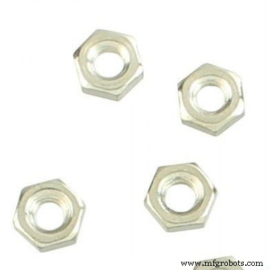
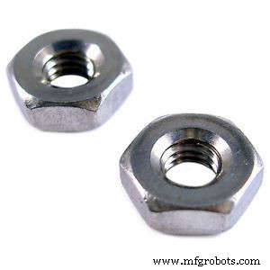
- M2 x 1,5mm nuts (x12)
- M3 x 10mm bolts (x8)
- M3 x 1,5mm nuts (x8)
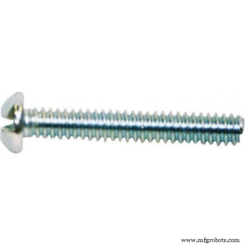
- 5/32" x 1" bolts (x3)
- 5/32" nuts (x6)
- Handheld selfie stick clip
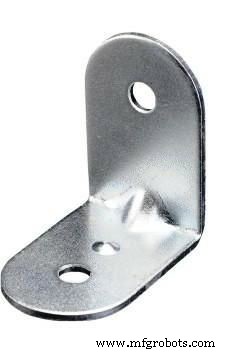
- 3 x 3 cm aluminum bracket (x4)
The construction of the structure of the base is divided in the following steps:
- Cut the acrylic base according to the dimensions in the 2D drawing;
- Drill the holes in the positions in shown in the 2D drawing;
- Mount the components with bolts and nuts according to the 3D drawing.
Unfortunately the diameter of the stepper motor shaft is greater than the orifice on the wheel. So you'll probably need to use glue to couple those components. For this tutorial I improvised a wood coupling between the motor shaft and the wheel.
FMAR9JBITKJE83H.123dxF21RD24ITKJE8AJ.dwgFPTGSODITKJE8AN.pdfStep 3: Cutting the structure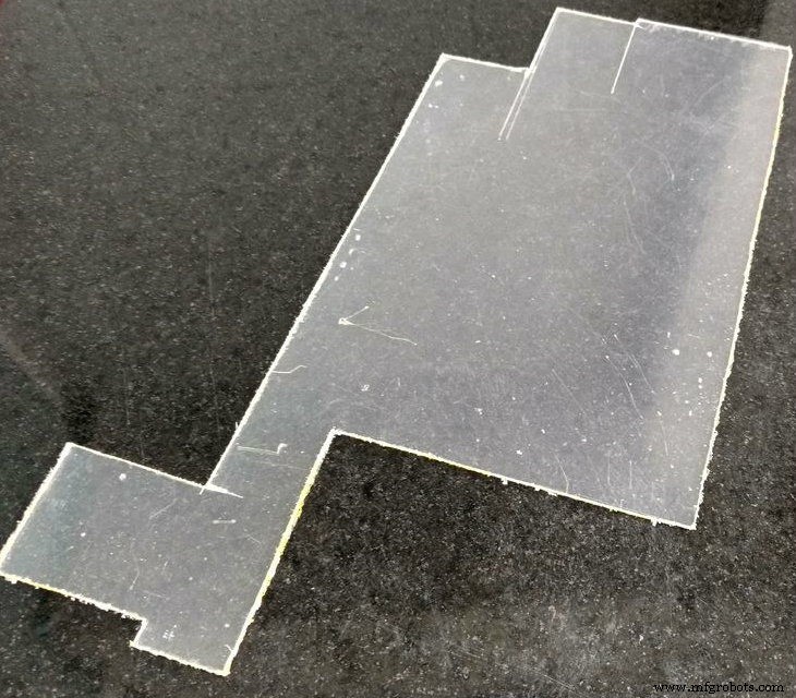
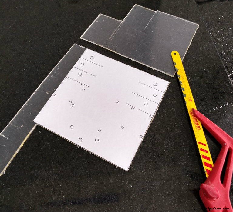
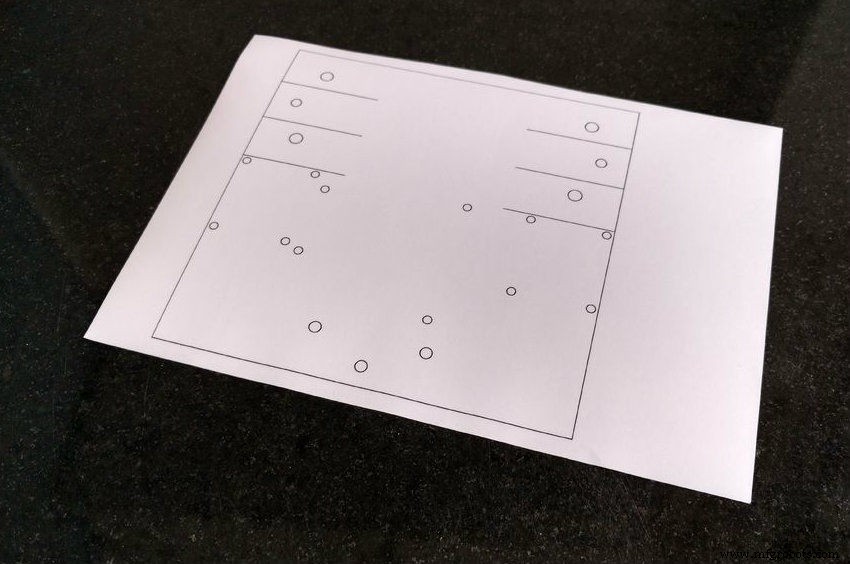
First you'll need to transfer the dimensions of your model to the acrylic sheet. Print your 2D drawing using an ordinary printer on an adhesive paper, then cut the paper in suitable dimensions and apply that mask on the surface of the acrylic.
You might use a hand saw to cut the acrylic according to your dimensions or use break technic described bellow.
With an utility knife and with the help of a ruler or a scale, cut the acrylic in straight lines. You won't need to cut all the way thru the sheet, just score it to create some tracks where the piece will be later cutted.
Place the acrylic on a flat surface, hold it in place with some clamps and apply some pressure until the sheet breaks into two. Repeat this process untill all the cuts are done. After that, you might use a sandpaper to smooth rough edges.
Step 4: Drilling the base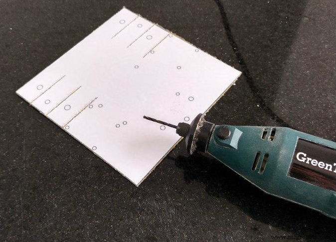
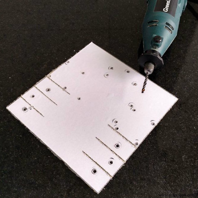
Drill the holes in the positions in shown in the 2D drawing (indicated in the mask) with a drilling machine.
Acrylic is relativelly easy to drill. So if you don't dispose of a drilling machine, you can drill the holes manually with a sharp tool, like an utility knife. You might also use it to enlarge small holes to fit bolts sizes.
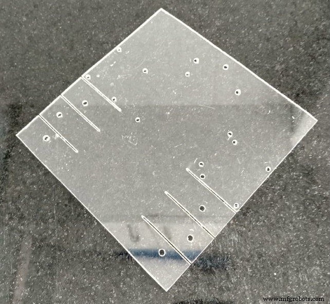
Remove the mask and your base will be ready.
Step 5: Assembling the structure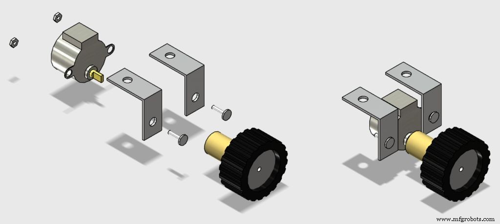
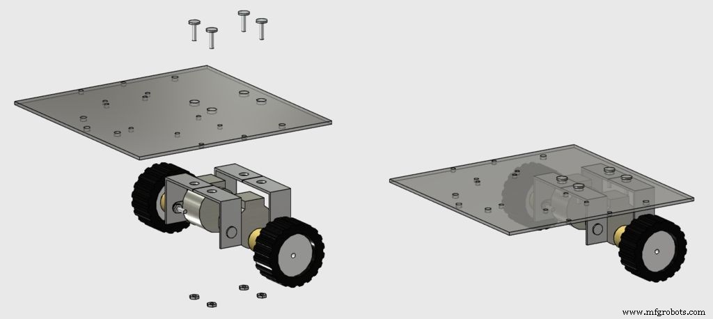
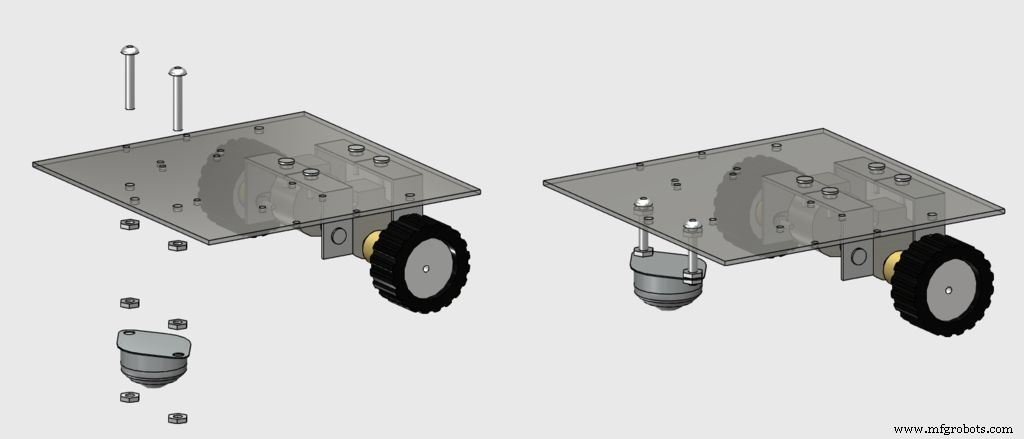
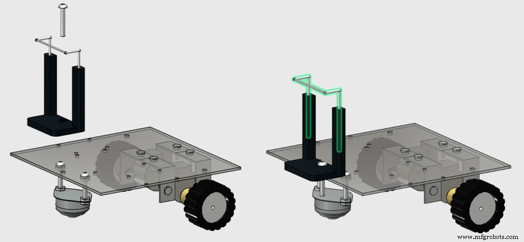
Mount the components with bolts and nuts according to the images, and your structure will be ready to go.
M3 bolts are used for the instalation of the stepper motors, while the 5/32" ones are used for the instalation of the front wheel and the smartphone clip.
Now take a break and start to assamble the circuit in the following step...
Step 6: Electronics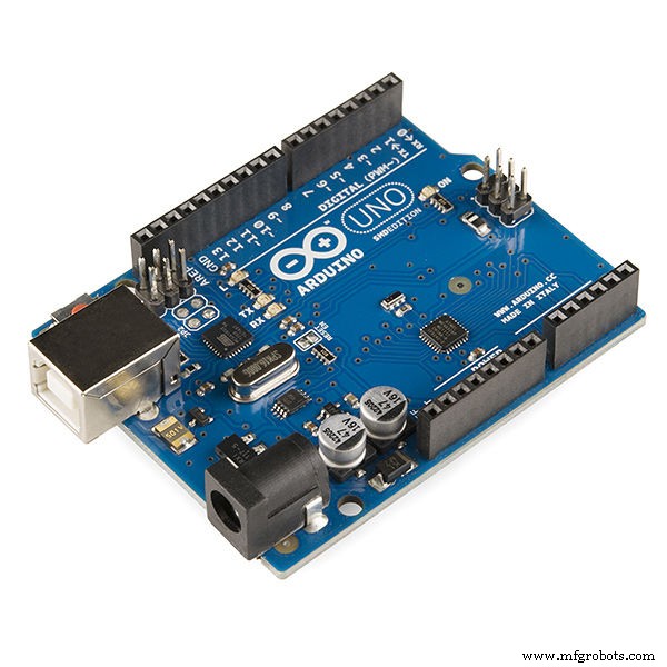
You'll need the following electronic components:
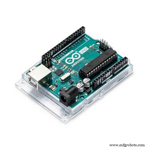
- Arduino Uno (buy)
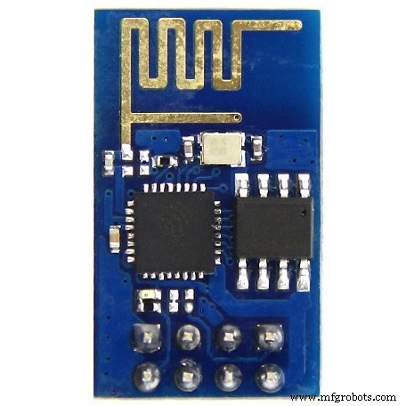
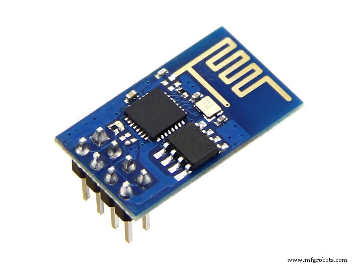
- ESP8266 (buy)
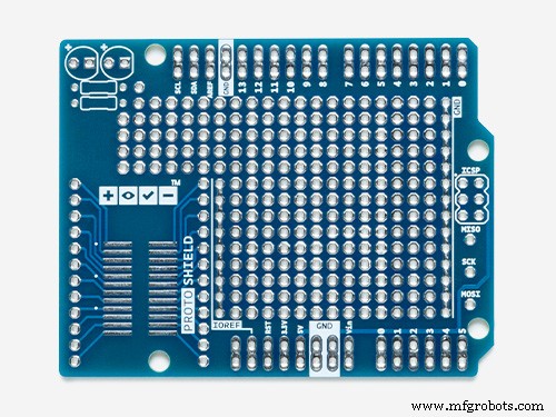
- Protoshield (for a more compact version) or an ordinary breadboard (buy)
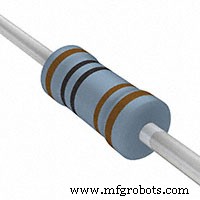
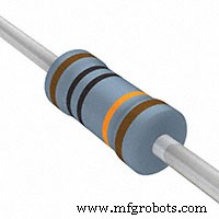
- 1 kohm resistor (x2)
- 10 kohm resistor (x1)
- Some jumper wires
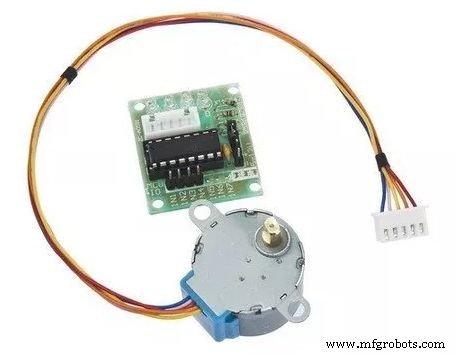
- Stepper motor with ULN2003driver (x2) (buy / buy)
- A computer (for compiling and uploading Arduino code)
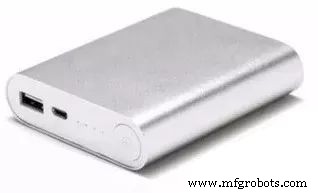
- Power bank (buy)
- USB cable
You won't need specific tools for the assembly of the circuit. All the components can be found online on your favourite e-commerce store. The circuit is powered by a power bank connected to Arduino's USB port.
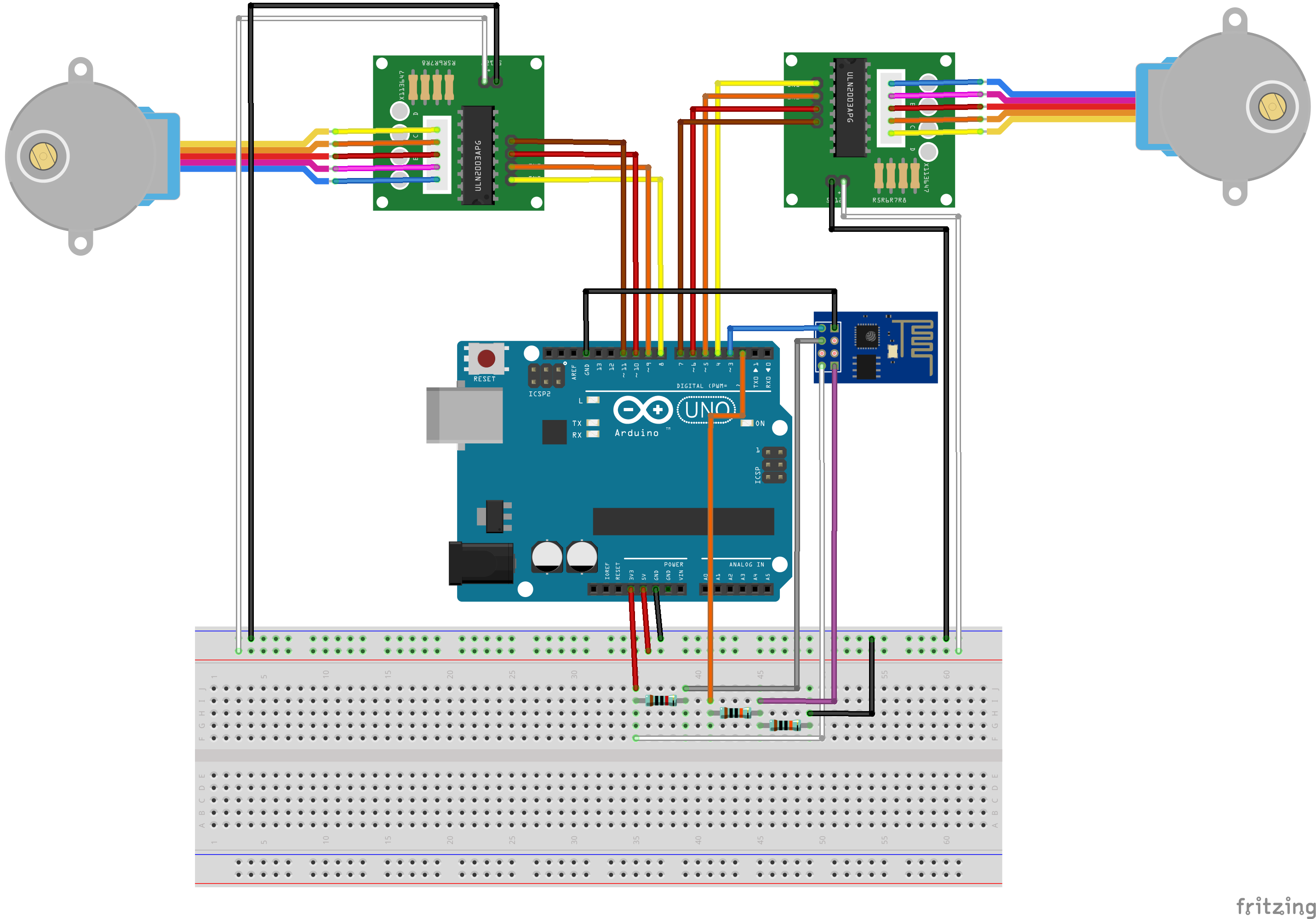
Connect all the componets according to the schematic. You'll need some jumper wires to connect the ESP-8266 module and the stepper motors. You might use a protoshield (for a more compact circuit), an ordinary breadboard, or design you own Arduino shield.Plug the USB cable to the Arduino Uno board and proceed to the next step.
Step 7: Arduino CodeInstall the latest Arduino IDE. In this project stepper.h library was used for the control of the stepper motors. No additional library was needed for communication with ESP-8266 module. Please check the baudrate of you ESP8266 and set it properly in the code.
Download Arduino code (stepperRobot.ino) and replace the XXXXX by your wifi router SSID and YYYYY by router password. Connect the Arduino board to your computer USB port and upload the code.
FG1K5KJITKJFW2R.inoStep 8: Android IP cam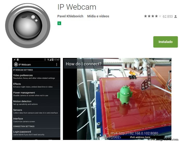
An Android smartphone was used to broadcast the video and audio from the robot to the control interface. You may find the app on Google Play store (https://play.google.com/store/apps/details?id=com.pas.webcam).
Install it and move to next step.
Step 9: Put the circuits in the robot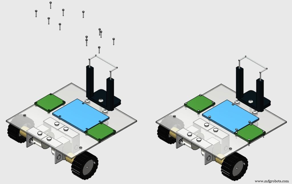
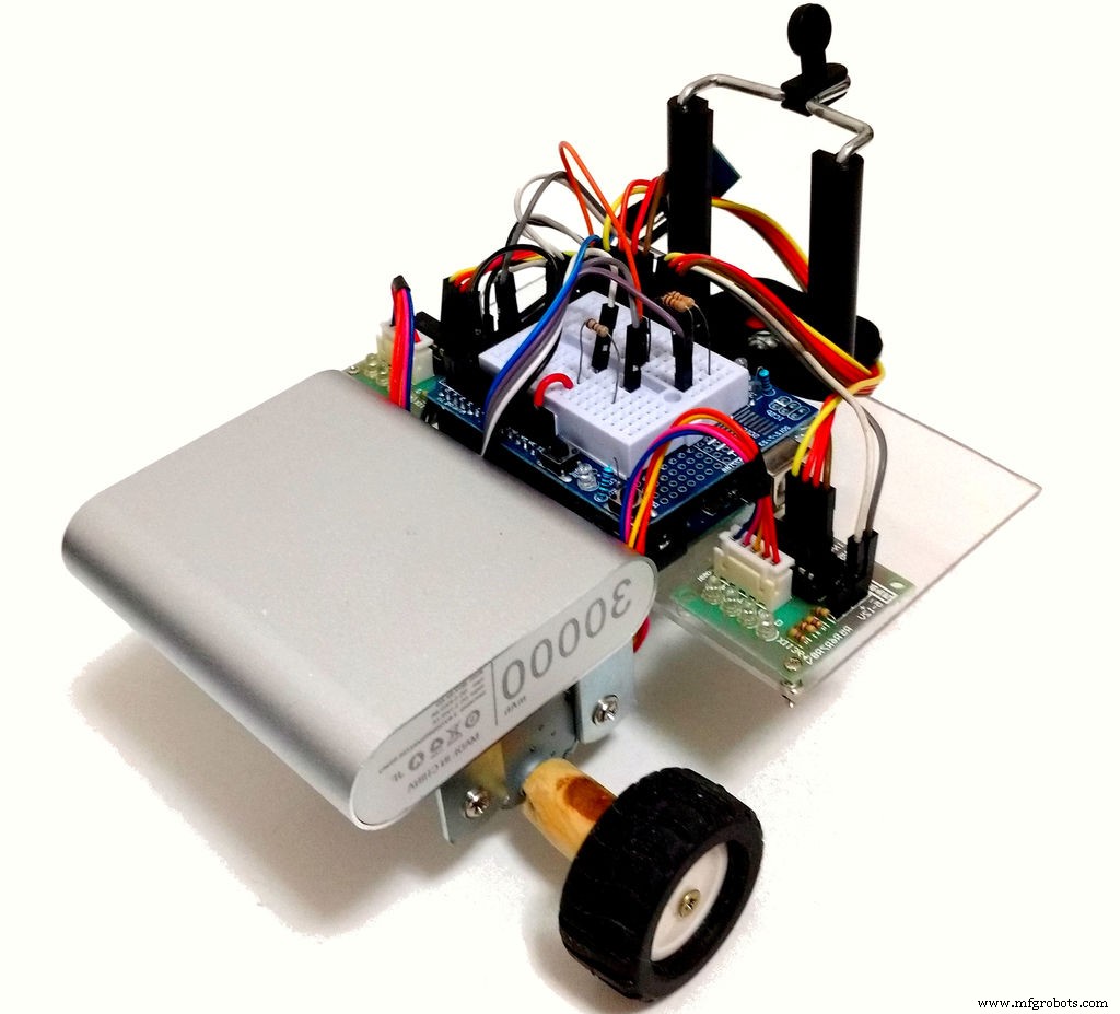
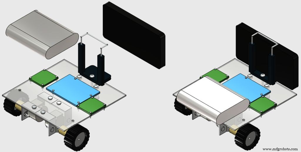
Install the circuits in the top of the robot using some M1 bolts, as shown in the images.
After that, glue your power bank in the back of the robot using a double sided tape (because it's easy to remove later), and put your smartphone in the clip.
Step 10: Web-based control interface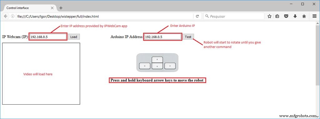
A html interface was designed for the control of the robot.
Download interface.rar and extract all the files to a given folder. Then open it on Firefox.
A textbox form is used in that interface to enter IP addresses of the ESP module and of the video/audio server (from Android IP Webcam app).
There is a test but, which will make the robot spin until anoter command is received. Keyboard arrow keys are used for moving the robot forward or backward, and to rotate left or right.
FQTAWF5ITKJFW4O.rarStep 11: UsageWhen the Arduino is restarted, it will try to connect your wi-fi network automatically. Use the Serial Monitor to check if the connection was successfull, and to obtain which IP was assigned to your ESP-8266 by your router. Open the html file in an internet browser (Firefox) and inform this IP address in the textbox.
You might also user other means to find out which IP address you router assigned to your device.
Disconnect the the Arduino Uno from your computer and connect it to the power bank. Wait for it to connect again.
Launch IP Webcam app in the smartphone attached to the robot. Type the video/audio IP on your control interface and connect to the server and you'll be ready to go. You might need to reduce the resolution of the video in the app to reduce the delay between during the transmission.
Click and hold the arrow buttons of your keyboard to rotate the robot or move it forward/backward and have fun exploring your environment.
Code
- Arduino
- html control interface
ArduinoArduino
Arduino code.//include libraries
#include <SoftwareSerial.h>
#include <Stepper.h>
SoftwareSerial esp8266(3, 2); //RX pin = 3, TX pin = 2
//definition of variables
#define DEBUG true //show messages between ESP8266 and Arduino in serial port
const int stepsPerRevolution = 500;
int state = 5;
Stepper rightStepper(stepsPerRevolution, 8,10,9,11);
Stepper leftStepper(stepsPerRevolution, 4,6,5,7);
//*****
//SETUP
//*****
void setup()
{
//start communication
Serial.begin(9600);
esp8266.begin(19200);
sendData("AT+RST\r\n", 2000, DEBUG); //reset module
sendData("AT+CWMODE=1\r\n", 1000, DEBUG); //set station mode
sendData("AT+CWJAP=\"XXXXX\",\"YYYYY\"\r\n", 2000, DEBUG); //connect wi-fi network
while(!esp8266.find("OK")) { //wait for connection
}
sendData("AT+CIFSR\r\n", 1000, DEBUG); //show IP address
sendData("AT+CIPMUX=1\r\n", 1000, DEBUG); //allow multiple connections
sendData("AT+CIPSERVER=1,80\r\n", 1000, DEBUG); // start web server on port 80
//Define motor speed
rightStepper.setSpeed(60);
leftStepper.setSpeed(60);
}
void loop()
{
if (esp8266.available()) //verify incoming data
{
if (esp8266.find("+IPD,")) //if there is a message
{
String msg;
esp8266.find("?"); //look for the message
msg = esp8266.readStringUntil(' '); //read whole message
String command = msg.substring(0, 3); //first 3 characters = command
String valueStr = msg.substring(4); //next 3 characters = value
int value = valueStr.toInt();
if (DEBUG) {
Serial.println(command);
Serial.println(value);
}
//move forward
if(command == "cm1") {
state = 1;
}
//move backward
if(command == "cm2") {
state = 2;
}
//turn right
if(command == "cm3") {
state = 3;
}
//turn left
if(command == "cm4") {
state = 4;
}
//do nothing
if(command == "cm5") {
state = 5;
}
}
}
//move forward
if (state == 1) {
rightStepper.step(1);
leftStepper.step(-1);
}
//move backward
if (state == 2) {
rightStepper.step(-1);
leftStepper.step(1);
}
//move right
if (state == 3) {
rightStepper.step(1);
leftStepper.step(1);
}
//move left
if (state == 4) {
rightStepper.step(-1);
leftStepper.step(-1);
}
//do nothing
if (state == 5) {
}
}
//*******************
//Auxiliary functions
//*******************
String sendData(String command, const int timeout, boolean debug)
{
String response = "";
esp8266.print(command);
long int time = millis();
while ( (time + timeout) > millis())
{
while (esp8266.available())
{
char c = esp8266.read();
response += c;
}
}
if (debug)
{
Serial.print(response);
}
return response;
}
html control interfaceHTML
No preview (download only).
Custom parts and enclosures
123D design file.robot.123dx2D design of the base.base.dwgSchematics
Circuit schematicBreadboard connection of the circuitFritzing file of the circuitwistepper%20-%20rev1.fzzManufacturing process
- Build a Bluetooth‑Controlled Raspberry Pi Robot with Audio Feedback
- Build an Internet‑Controlled Video‑Streaming Robot with Arduino & Raspberry Pi
- Integrating a DFRobot Capacitive Fingerprint Sensor with Arduino or ESP8266
- Control Your Roomba Create 2 Using Arduino and Android: A Step-by-Step Guide
- Build a Voice‑Controlled Robot with Arduino Nano
- Build a 4-Wheel Arduino Robot Controlled via Dabble App
- Build a 2‑Wheel Voice‑Controlled Robot with Arduino & BitVoicer Server
- Build Your Own AI Assistant Robot Using Arduino & Python
- Build an ESP8266 Telegram Bot: IoT Control Made Easy
- Master Stepper Motor Control with Arduino & A4988 Driver – Step-by-Step Guide