


Advanced RFID Attendance System v2.0 – Ethernet‑Free Solution
Components and supplies
 |
| × | 1 | |||
 |
| × | 1 | |||
| × | 1 |
Apps and online services
| ||||
|
About this project
First version of our “Online RFID Attendance System (Without Ethernet)” might be seem a little bit complicated for those hobbyists that don't have programming skills. With Online RFID Attendance System Version 2, we have come one step forward and eliminated coding part. With doing just some connections, you will be able to create your own Online Attendance System.
In this version of attendance system we are going to launch attendance system with all requirements of a real attendance system. It has a LCD Display.
How it Works?Circuit :
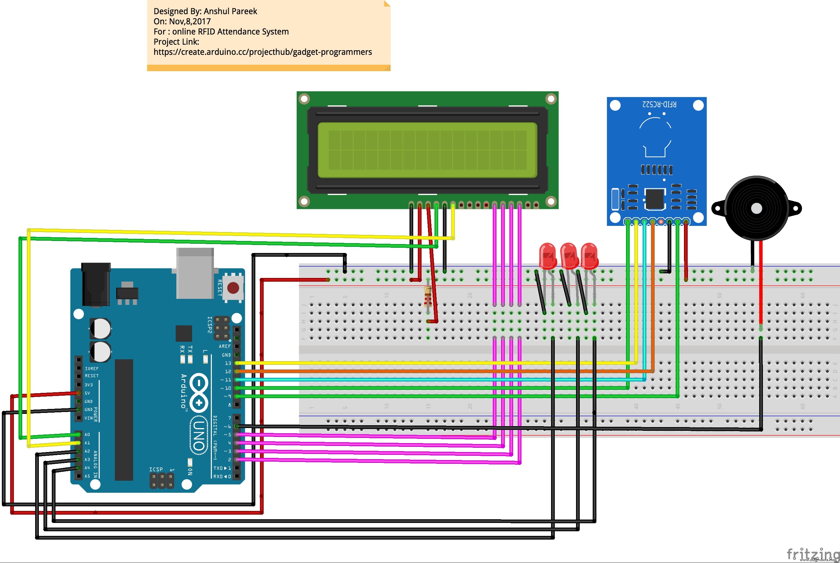
If you have confusion in connections then see in schematics section for Pin Connections.
The circuit for LCD SCREEN:
pin3 to grd with 220 ohm resister
LCD RS pin to digital pin A0
LCD Enable pin to digital pin A1
LCD D4 pin to digital pin 5
LCD D5 pin to digital pin 4
LCD D6 pin to digital pin 3
LCD D7 pin to digital pin 2
LCD R/W pin to ground
LCD VSS pin to ground
LCD VCC pin to 5V
Programming:
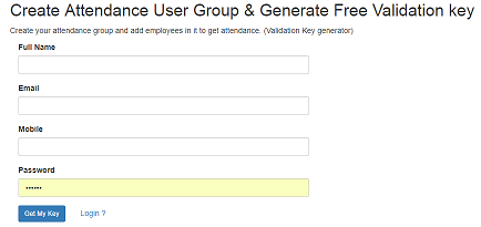
Step 1: To use our Online RFID Attendance System, you need to do below steps:
- · Create Attendance User Group
- · Generate Validation key
To do above steps, please go to below URL and create Attendance User Group and Generate Free Validation Key.
Keep this validation key.
URL: http://www.parikshacrack.com/gadgetProgrammers/user_group.html
Step 2: Please download files from below URL which is required to sync Arduino and Our Web Application.
http://www.parikshacrack.com/gadgetProgrammers/addRFIDTagsProg.zip
http://www.parikshacrack.com/gadgetProgrammers/markattendancewin64.zip
Note: This is only for windows OS. we are working hard for others OS.
Extract files from above two zip folders and save these files in your PC and choose according to your windows architecture. (32 or 64 bit pc).
Step 3: Connect Arduino and RFID Reader to the same PC.
Step 4: Please copy and paste Arduino code as given in code section to Arduino editor. Now run and upload Arduino code to device.
Step 5: Now run desktop Application “addRFIDTagsProg” that you can find in Folder “addRFIDTagsProg.zip”.
If everything is connected perfectly, then Application “addRFIDTagsProg” will be opened and text box will be shown as in below image otherwise a blank screen will be shown.
Given below diagram is asking for port which to be choosen for communication please choose as per your availability.
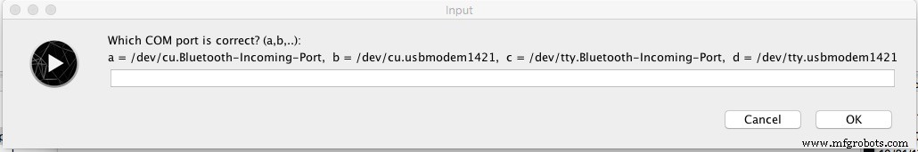
after this you will see below given window.
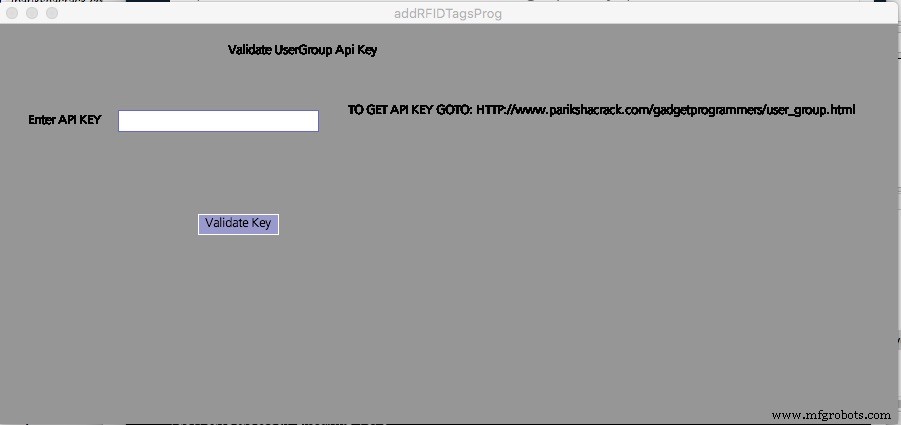
Now enter Validation key that you have generated in Step 1 and Press button validate key.
It validates you.
After Validation you can add users Using the above same window it will prompt for validation key only once.
For adding user please run above given program after validation then it will show you the screen as given below choose available port again:

After choosing correct free port it will show below given screen.
Above screen is used to add User for this you need to approximate your card in front of RFID RC522 Then it will show you the TAG UID in front of UID and then you just need to enter user name who will belong to this card and press enter (button will appear after approximating card).
If user gets added it will show you message of success and you can view user on web panel.
URL: http://www.parikshacrack.com/gadgetProgrammers/index.php
Step 6: Now you are able to add user (employees/students) in your user group. For that, you need to Login to our web Application. Go to below URL and Login.
URL: http://www.parikshacrack.com/gadgetProgrammers/index.php
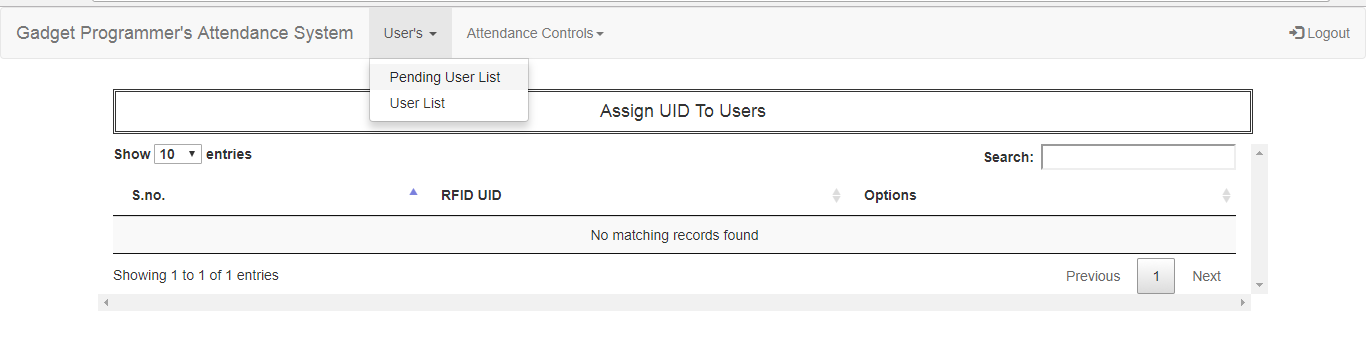
Go to Tab User’s -> Pending User List, from here you can assign RFID Tags to their employee/students.
Step 7: Run desktop Application “markOnlineAttendance” that you can find in folder “markattendancewin64.zip”.
A screen will be opened as shown in below image showing Status: connected.
To mark attendance, keep RFID Tags close to RFID Reader for some seconds and attendance will be marked for the person to whom this RFID Tags belongs.

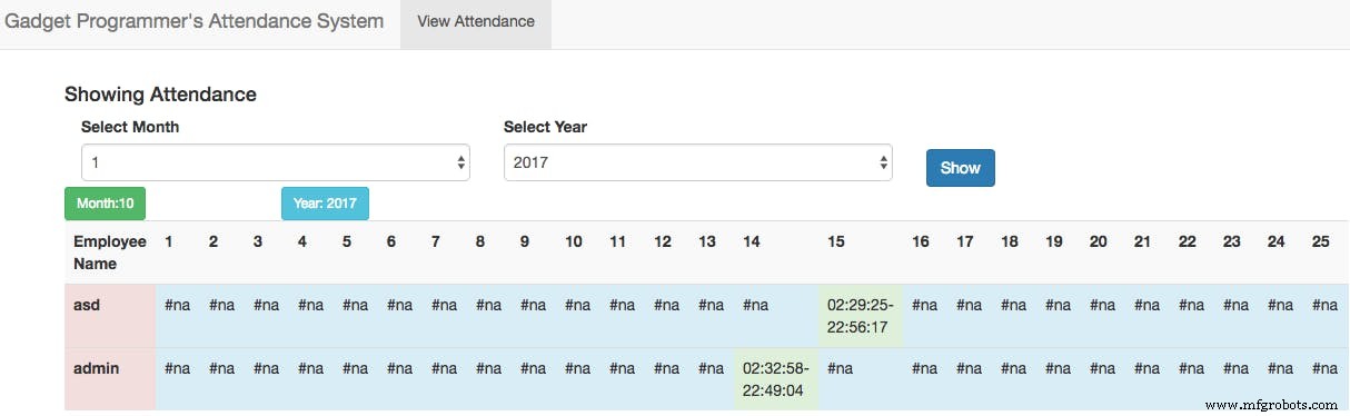
Step 8: To see attendance of all employees/students in a month or in year, Please follow following steps.
- Go to Tab Attendance Controls -> View Attendance.
- Select Month and year.
- Click on Button “show”.
A list should be shown as below image.
Hooray !!! It is done.
If you like please give respect.
Please shout in comment box if you have any query .
Code
- Arduino Code
Arduino CodeArduino
This code used to read user 8 Digit UID (ID CARD) and print on serial printer and to send it to processing./*
--------------------------------------------------------------------------------------------------------------------
Example sketch/program showing how to read new NUID from a PICC to serial.
--------------------------------------------------------------------------------------------------------------------
This is a MFRC522 library example; for further details and other examples see: https://github.com/miguelbalboa/rfid
Example sketch/program showing how to the read data from a PICC (that is: a RFID Tag or Card) using a MFRC522 based RFID
Reader on the Arduino SPI interface.
When the Arduino and the MFRC522 module are connected (see the pin layout below), load this sketch into Arduino IDE
then verify/compile and upload it. To see the output: use Tools, Serial Monitor of the IDE (hit Ctrl+Shft+M). When
you present a PICC (that is: a RFID Tag or Card) at reading distance of the MFRC522 Reader/PCD, the serial output
will show the type, and the NUID if a new card has been detected. Note: you may see "Timeout in communication" messages
when removing the PICC from reading distance too early.
@license Released into the public domain.
The circuit for LCD SCREEN:
pin3 to grd with 220 ohm resister
LCD RS pin to digital pin A0
LCD Enable pin to digital pin A1
LCD D4 pin to digital pin 5
LCD D5 pin to digital pin 4
LCD D6 pin to digital pin 3
LCD D7 pin to digital pin 2
LCD R/W pin to ground
LCD VSS pin to ground
LCD VCC pin to 5V
10K resistor:
ends to +5V and ground
wiper to LCD VO pin (pin 3)
RFID Circuit :
Typical pin layout used:
-----------------------------------------------------------------------------------------
MFRC522 Arduino Arduino Arduino Arduino Arduino
Reader/PCD Uno/101 Mega Nano v3 Leonardo/Micro Pro Micro
Signal Pin Pin Pin Pin Pin Pin
-----------------------------------------------------------------------------------------
RST/Reset RST 9 5 D9 RESET/ICSP-5 RST
SPI SS SDA(SS) 10 53 D10 10 10
SPI MOSI MOSI 11 / ICSP-4 51 D11 ICSP-4 16
SPI MISO MISO 12 / ICSP-1 50 D12 ICSP-1 14
SPI SCK SCK 13 / ICSP-3 52 D13 ICSP-3 15
*/
#include <SPI.h>
#include <MFRC522.h>
// include the library code:
#include <LiquidCrystal.h>
// initialize the library by associating any needed LCD interface pin
// with the arduino pin number it is connected to
const int rs = A0, en = A1, d4 = 5, d5 = 4, d6 = 3, d7 = 2;
LiquidCrystal lcd(rs, en, d4, d5, d6, d7);
#define SS_PIN 10
#define RST_PIN 9
int writeVal;
int greenLedPin = A2;
int redLedPin = A3;
int orangeLedPin = 6;
int buzzerPin = A4;
boolean chkConn = false;
MFRC522 rfid(SS_PIN, RST_PIN); // Instance of the class
MFRC522::MIFARE_Key key;
// Init array that will store new NUID
byte nuidPICC[4];
boolean isValidating = false;
void setup() {
Serial.begin(9600);
SPI.begin(); // Init SPI bus
rfid.PCD_Init(); // Init MFRC522
pinMode(greenLedPin, OUTPUT);
pinMode(redLedPin, OUTPUT);
digitalWrite(buzzerPin, OUTPUT);
for (byte i = 0; i < 6; i++) {
key.keyByte[i] = 0xFF;
}
lcd.begin(16, 2);
lcd.setCursor(0, 0);
// lcd.print("Welcome To GadgetProgrammer");
// for (int i = 0; i < 26; i++) {
// lcd.scrollDisplayRight();
// delay(100);
// }
lcd.begin(16, 2);
lcd.setCursor(0, 0);
lcd.print("GadgetProgrammer");
delay(100);
lcd.setCursor(0, 1);
lcd.print(" Not Connected! ");
establishConnection();
}
void loop() {
lcd.setCursor(0, 1);
char retOutput;
if (Serial.available() > 0) {
retOutput = Serial.read();
lcd.blink();
if (retOutput == 'A') {
chkConn = true;
analogWrite(orangeLedPin,0);
lcd.print("Swipe Your Card!");
}
if(retOutput == 'V'){
analogWrite(orangeLedPin,1000);
lcd.print("Validating Group");
isValidating = true;
delay(1000);
}
if(retOutput == 'S'){
lcd.print("Validation Done!");
glowGreenLed(1000);
isValidating = false;
delay(1000);
}
}
if (chkConn && !retOutput != "") {
if (retOutput == '1') {
lcd.print("Attendance Done!");
glowGreenLed(1000);
delay(4000);
}
else if (retOutput == '0') {
lcd.print("Network Error !");
glowRedLed(1000);
delay(4000);
} else if (retOutput == '2') {
lcd.print("User Not Found!");
glowRedLed(1000);
delay(4000);
} else if (retOutput == '5') {
lcd.print("Network Error!");
glowRedLed(1000);
delay(4000);
}
//if not in validation process then swipe your card
if(isValidating == false){
lcd.setCursor(0, 1);
analogWrite(orangeLedPin,0);
lcd.print("Swipe Your Card!");
}
//lcd.clear();
// Look for new cards
}
if ( ! rfid.PICC_IsNewCardPresent())
return;
// Verify if the NUID has been readed
if ( ! rfid.PICC_ReadCardSerial())
return;
//Serial.print(F("PICC type: "));
MFRC522::PICC_Type piccType = rfid.PICC_GetType(rfid.uid.sak);
//Serial.println(rfid.PICC_GetTypeName(piccType));//Printing type of card
// Check is the PICC of Classic MIFARE type
if (piccType != MFRC522::PICC_TYPE_MIFARE_MINI &&
piccType != MFRC522::PICC_TYPE_MIFARE_1K &&
piccType != MFRC522::PICC_TYPE_MIFARE_4K) {
//Serial.println(F("Your tag is not of type MIFARE Classic."));
return;
}
String s;
for (byte i = 0; i < 4; i++) {
nuidPICC[i] = rfid.uid.uidByte[i];
}
//Serial.println(F("The NUID tag is:"));
//Serial.print(F("In hex: "));
printHex(rfid.uid.uidByte, rfid.uid.size);
Serial.println();
lcd.setCursor(0,1);
lcd.print("Reading Card...!");
// Halt PICC
rfid.PICC_HaltA();
// Stop encryption on PCD
rfid.PCD_StopCrypto1();
delay(1000);
}
/**
Helper routine to dump a byte array as hex values to Serial.
*/
void printHex(byte *buffer, byte bufferSize) {
for (byte i = 0; i < bufferSize; i++) {
Serial.print(buffer[i] < 0x10 ? "0" : "");
Serial.print(buffer[i], HEX);
}
}
/**
Helper routine to dump a byte array as dec values to Serial.
*/
void printDec(byte *buffer, byte bufferSize) {
for (byte i = 0; i < bufferSize; i++) {
Serial.print(buffer[i] < 0x10 ? "0" : "");
Serial.print(buffer[i], DEC);
}
}
void glowGreenLed(int delaytime) {
digitalWrite(orangeLedPin,LOW);
digitalWrite(greenLedPin, HIGH);
digitalWrite(redLedPin, LOW);
tone(buzzerPin, 5000, 300);
if (delaytime > 0) {
delay(delaytime);
digitalWrite(greenLedPin, LOW);
noTone(buzzerPin);
}
}
void glowRedLed(int delaytime) {
digitalWrite(orangeLedPin,LOW);
digitalWrite(greenLedPin, LOW);
digitalWrite(redLedPin, HIGH);
digitalWrite(buzzerPin, HIGH);
delay(1000);
tone(buzzerPin, 5000);
//noTone(buzzerPin);
if (delaytime > 0) {
delay(delaytime);
digitalWrite(redLedPin, LOW);
noTone(buzzerPin);
}
}
void glowOrangeLed(){
analogWrite(orangeLedPin,100);
delay(100);
}
//contacting with processing sending A to Serial Port
void establishConnection() {
while (Serial.available() <= 0 && !chkConn) {
Serial.println("A");
glowOrangeLed();
delay(200);
}
}
void printLcdMsg(String msg, int col, int row) {
if (msg.equals("") || row < 0 || col < 0) {
row = 0;
col = 1;
}
lcd.setCursor(col, row);
lcd.print(msg);
}
Schematics
pin_connections_of_arduino_and_lcd_yD9G43NUd9.tiffpin_connections_of_arduion_and_rfid_7DFKgigFOA.tiffManufacturing process
- The Rolling Pin: From Etruscan Origins to Modern Craftsmanship
- The Evolution and Craftsmanship of Modern Bowling Pins
- Primal Display: Build a Raspberry Pi LCD Temperature Monitor
- Elkem Silicones Unveils LSR Select: Low‑Temperature Cure and Custom Formulation for 50% Faster Cycle Times
- Reliable Arduino-Based RFID Attendance System Powered by Python
- Real-Time RFID Attendance System Powered by Arduino & Google Sheets
- Secure Arduino Fingerprint Attendance System with Cloud Data Storage
- Build a Reliable LCD Stopwatch with Arduino Nano – No Potentiometer Needed
- Arduino Temperature Sensor Project: Read, Convert, and Display Fahrenheit
- Secure Arduino‑Based Keyless Door Lock with LCD Display and 4×4 Keypad