


Precise Heart Rate & SpO₂ Monitoring with MAX30102 Pulse Oximeter on Arduino
Components and supplies
 |
| × | 1 | |||
| × | 1 | ||||
 |
| × | 1 | |||
 |
| × | 1 |
About this project
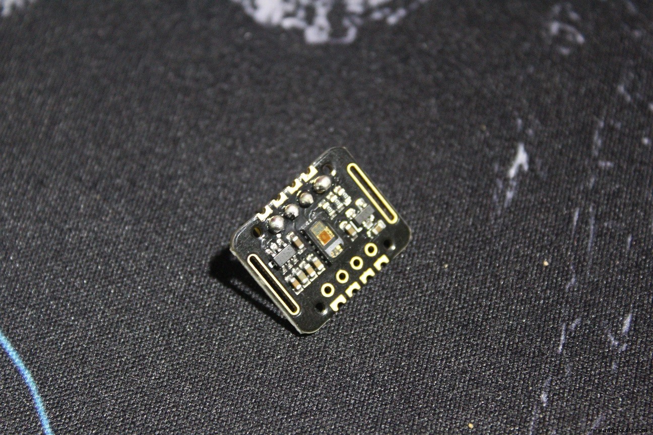
IntroHi, in this tutorial we gonna interface MAX30102: pulse oximetry and heart rate monitor module with Arduino UNO board, and then make a project for measuring BPM using this module + OLED display and a Buzzer.
BPM are the "beats per minute" and they are around 65-75 while resting for a normal person, athletics may have lower than that, and the SpO2 is the Oxygen saturation level, and for a normal person it's above 95%.
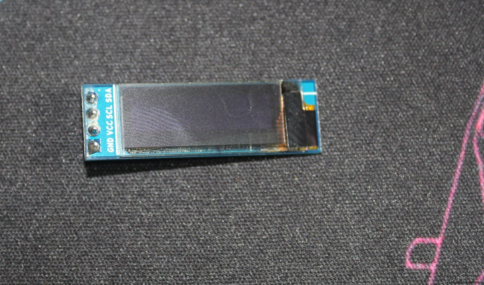
The MAX30102 can be found in different modules, I have a WAVGAT version, it's not a problem as long as the IC is MAX30102.
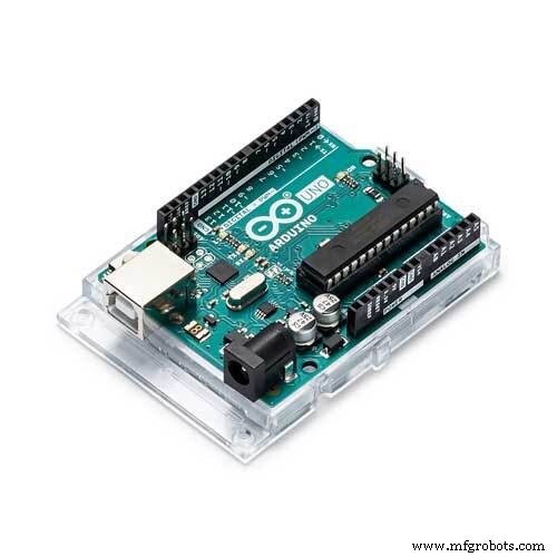
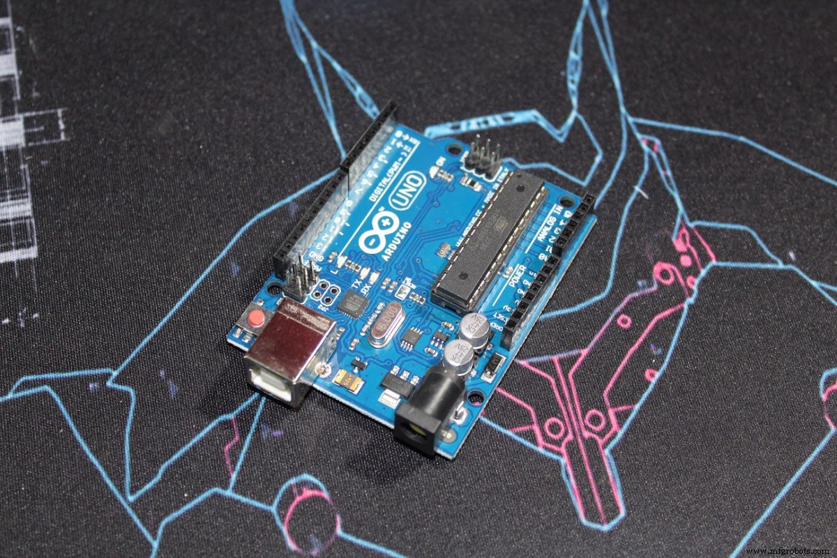
ComponentsHere are the things I'm gonna use

The codes I used in the tutorial are pretty clear and they are just examples from the Sparkfun_MAX3010x library.
For the code I made for the OLED and Buzzer, it's a modified version of the "HeartRate" example, it asks you to put your finger on the sensor.
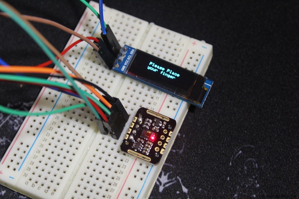
Once you put your finger, remain calm for a while, until you start hearing the Buzzer's "Beeps" synchronized with your heart beats or the OLED animation is synchronized with it, and then you can read a correct BPM.
N.B: In the code I actually print the Average BPM, since it do the average of 4 BPMs it's more accurate just give it some time.
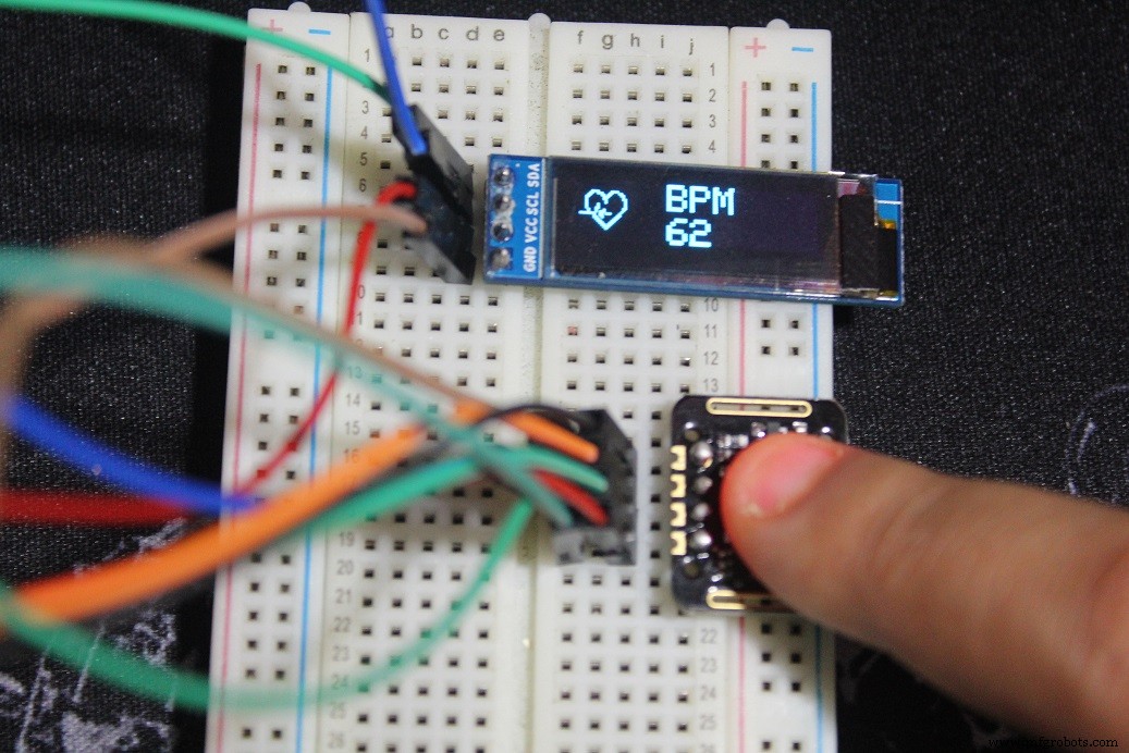
The heart (small) you see is a bitmap picture, and everytime the sensor detects a heart beat we switch to another heart (big) bitmap picture for a while and it gives the impression of a heart beats alongside with a beep from the buzzer.
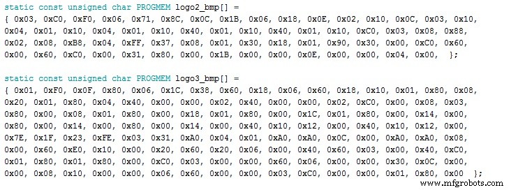
Here are the two bitmaps in the code that we call later on the code
To make these, Look for a picture (black with white background) for wathever you want to see in the screen just don't forget about the size, the one I'm using is 128x32 px and the pictures are smaller than that (32x32 px) and (24x21 px)
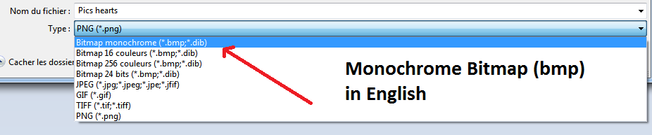
Download LCD Assistant and open it (few steps below)

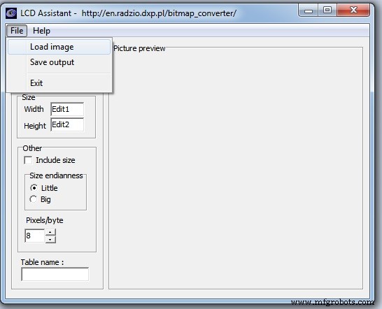


And here are your "numbers"

And here's how I called it in the code
display.drawBitmap(5, 5, logo2_bmp, 24, 21, WHITE);
Which means
display.drawBitmap(Starting x pos, Starting y pos, Bitmap name, Width, Height, Color);
And as you can see in the code one is called when a finger is detected and the other one if a heart beat is detected.
And here you go make what you want.
Code
- MAX_BPM_OLED_Buzzer.ino
MAX_BPM_OLED_Buzzer.inoArduino
Modified from the SparkFun MAX3010x library/* This code works with MAX30102 + 128x32 OLED i2c + Buzzer and Arduino UNO
* It's displays the Average BPM on the screen, with an animation and a buzzer sound
* everytime a heart pulse is detected
* It's a modified version of the HeartRate library example
* Refer to www.surtrtech.com for more details or SurtrTech YouTube channel
*/
#include <Adafruit_GFX.h> //OLED libraries
#include <Adafruit_SSD1306.h>
#include <Wire.h>
#include "MAX30105.h" //MAX3010x library
#include "heartRate.h" //Heart rate calculating algorithm
MAX30105 particleSensor;
const byte RATE_SIZE = 4; //Increase this for more averaging. 4 is good.
byte rates[RATE_SIZE]; //Array of heart rates
byte rateSpot = 0;
long lastBeat = 0; //Time at which the last beat occurred
float beatsPerMinute;
int beatAvg;
#define SCREEN_WIDTH 128 // OLED display width, in pixels
#define SCREEN_HEIGHT 32 // OLED display height, in pixels
#define OLED_RESET -1 // Reset pin # (or -1 if sharing Arduino reset pin)
Adafruit_SSD1306 display(SCREEN_WIDTH, SCREEN_HEIGHT, &Wire, OLED_RESET); //Declaring the display name (display)
static const unsigned char PROGMEM logo2_bmp[] =
{ 0x03, 0xC0, 0xF0, 0x06, 0x71, 0x8C, 0x0C, 0x1B, 0x06, 0x18, 0x0E, 0x02, 0x10, 0x0C, 0x03, 0x10, //Logo2 and Logo3 are two bmp pictures that display on the OLED if called
0x04, 0x01, 0x10, 0x04, 0x01, 0x10, 0x40, 0x01, 0x10, 0x40, 0x01, 0x10, 0xC0, 0x03, 0x08, 0x88,
0x02, 0x08, 0xB8, 0x04, 0xFF, 0x37, 0x08, 0x01, 0x30, 0x18, 0x01, 0x90, 0x30, 0x00, 0xC0, 0x60,
0x00, 0x60, 0xC0, 0x00, 0x31, 0x80, 0x00, 0x1B, 0x00, 0x00, 0x0E, 0x00, 0x00, 0x04, 0x00, };
static const unsigned char PROGMEM logo3_bmp[] =
{ 0x01, 0xF0, 0x0F, 0x80, 0x06, 0x1C, 0x38, 0x60, 0x18, 0x06, 0x60, 0x18, 0x10, 0x01, 0x80, 0x08,
0x20, 0x01, 0x80, 0x04, 0x40, 0x00, 0x00, 0x02, 0x40, 0x00, 0x00, 0x02, 0xC0, 0x00, 0x08, 0x03,
0x80, 0x00, 0x08, 0x01, 0x80, 0x00, 0x18, 0x01, 0x80, 0x00, 0x1C, 0x01, 0x80, 0x00, 0x14, 0x00,
0x80, 0x00, 0x14, 0x00, 0x80, 0x00, 0x14, 0x00, 0x40, 0x10, 0x12, 0x00, 0x40, 0x10, 0x12, 0x00,
0x7E, 0x1F, 0x23, 0xFE, 0x03, 0x31, 0xA0, 0x04, 0x01, 0xA0, 0xA0, 0x0C, 0x00, 0xA0, 0xA0, 0x08,
0x00, 0x60, 0xE0, 0x10, 0x00, 0x20, 0x60, 0x20, 0x06, 0x00, 0x40, 0x60, 0x03, 0x00, 0x40, 0xC0,
0x01, 0x80, 0x01, 0x80, 0x00, 0xC0, 0x03, 0x00, 0x00, 0x60, 0x06, 0x00, 0x00, 0x30, 0x0C, 0x00,
0x00, 0x08, 0x10, 0x00, 0x00, 0x06, 0x60, 0x00, 0x00, 0x03, 0xC0, 0x00, 0x00, 0x01, 0x80, 0x00 };
void setup() {
display.begin(SSD1306_SWITCHCAPVCC, 0x3C); //Start the OLED display
display.display();
delay(3000);
// Initialize sensor
particleSensor.begin(Wire, I2C_SPEED_FAST); //Use default I2C port, 400kHz speed
particleSensor.setup(); //Configure sensor with default settings
particleSensor.setPulseAmplitudeRed(0x0A); //Turn Red LED to low to indicate sensor is running
}
void loop() {
long irValue = particleSensor.getIR(); //Reading the IR value it will permit us to know if there's a finger on the sensor or not
//Also detecting a heartbeat
if(irValue > 7000){ //If a finger is detected
display.clearDisplay(); //Clear the display
display.drawBitmap(5, 5, logo2_bmp, 24, 21, WHITE); //Draw the first bmp picture (little heart)
display.setTextSize(2); //Near it display the average BPM you can display the BPM if you want
display.setTextColor(WHITE);
display.setCursor(50,0);
display.println("BPM");
display.setCursor(50,18);
display.println(beatAvg);
display.display();
if (checkForBeat(irValue) == true) //If a heart beat is detected
{
display.clearDisplay(); //Clear the display
display.drawBitmap(0, 0, logo3_bmp, 32, 32, WHITE); //Draw the second picture (bigger heart)
display.setTextSize(2); //And still displays the average BPM
display.setTextColor(WHITE);
display.setCursor(50,0);
display.println("BPM");
display.setCursor(50,18);
display.println(beatAvg);
display.display();
tone(3,1000); //And tone the buzzer for a 100ms you can reduce it it will be better
delay(100);
noTone(3); //Deactivate the buzzer to have the effect of a "bip"
//We sensed a beat!
long delta = millis() - lastBeat; //Measure duration between two beats
lastBeat = millis();
beatsPerMinute = 60 / (delta / 1000.0); //Calculating the BPM
if (beatsPerMinute < 255 && beatsPerMinute > 20) //To calculate the average we strore some values (4) then do some math to calculate the average
{
rates[rateSpot++] = (byte)beatsPerMinute; //Store this reading in the array
rateSpot %= RATE_SIZE; //Wrap variable
//Take average of readings
beatAvg = 0;
for (byte x = 0 ; x < RATE_SIZE ; x++)
beatAvg += rates[x];
beatAvg /= RATE_SIZE;
}
}
}
if (irValue < 7000){ //If no finger is detected it inform the user and put the average BPM to 0 or it will be stored for the next measure
beatAvg=0;
display.clearDisplay();
display.setTextSize(1);
display.setTextColor(WHITE);
display.setCursor(30,5);
display.println("Please Place ");
display.setCursor(30,15);
display.println("your finger ");
display.display();
noTone(3);
}
}
SparkFun MAX3010x library
https://github.com/sparkfun/SparkFun_MAX3010x_Sensor_LibraryAdafruit SSD1306
https://github.com/adafruit/Adafruit_SSD1306Adafruit GFX library
https://github.com/adafruit/Adafruit-GFX-LibrarySchematics
Both modules have i²c interface, if you're using a 2 pin buzzer (-) with GND and (+) with a resistor then D3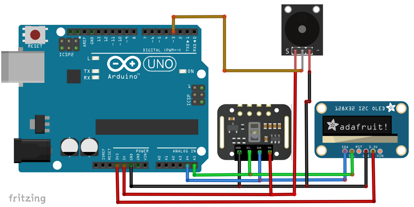
Manufacturing process
- Connect Multiple DS18B20 1‑Wire Sensors to a Raspberry Pi for Accurate Temperature Monitoring
- Remote Heart Rate Monitoring System with AWS IoT Alerts
- Build a Robot with Raspberry Pi and Python: A Complete Guide
- Integrating a Thermocouple Sensor with the Arduino Portenta H7 Using the MAX6675 IC
- Real‑Time IoT Heart Rate Monitor with Arduino & MAX30100
- Build an Accurate Heart‑Rate Monitor with a Photoresistor and Arduino
- Copper Electroplating Project: Build a Smart System with Arduino UNO
- Arduino Ultrasonic Distance & Temperature Monitor with LCD Alarm System
- Wireless ECG Heart Rate Monitor: Wearable Design with Arduino Nano & nRF24
- Maximize Workshop Space with Visual Components, Matterport & ProFeeder X Automation