


Spark Plug: Design, Materials, and Manufacturing – An Expert Overview
Background
The spark plug delivers a high‑temperature electric spark that ignites the air/fuel mixture in an internal combustion engine’s combustion chamber. It achieves this by arcing a precisely sized gap within the plug.
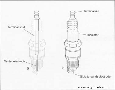
A spark plug consists of four main components: the center electrode, the insulator, the metal shell, and the side (ground) electrode. The center electrode is a thick, conductive wire that runs lengthwise through the plug, carrying electricity from the ignition system to the spark gap. The insulator, a ceramic sleeve, surrounds most of the center electrode and keeps the high voltage from leaking. The hexagonal metal shell, threaded to fit the cylinder head, anchors the plug. The side electrode, made of a nickel alloy, connects to the shell and points toward the center electrode, creating the spark gap that is typically 0.020–0.080 inch apart depending on engine design.
With hundreds of variations, spark plugs serve a wide range of engines—from automobiles, trucks, buses, and tractors to boats, aircraft, motorcycles, scooters, industrial machinery, oil field rigs, power mowers, and chainsaws. Specialty plugs, such as turbine igniters, power modern jet engines, while glow plugs are standard in diesel applications.
The heat range—or rating—of a spark plug describes how quickly heat is removed from the tip and transferred to the cylinder head. A tip that is too cold can foul with carbon or oil; a tip that is too hot can cause pre‑ignition or damage the electrode. Manufacturers adjust the insulator nose length to achieve the desired heat range: a longer conical nose yields a ‘hot’ plug, a shorter nose a ‘cold’ plug.
Under the hood, a spark plug faces corrosive gases at 4,500°F, crushing pressures of 2,000 psi, and electrical discharges up to 18,000 volts. These stresses repeat dozens of times per second and can total over a million cycles during a single day of driving.
History
The concept of using an electric spark to ignite a fuel‑air mix dates back to 1777, when Alessandro Volta fired a Leyden jar at a toy pistol loaded with marsh gas and air. The first true spark plug was developed in 1860 by French engineer Jean Lenoir, who combined an insulator, electrodes, and spark gap into a single unit. Lenoir refined his design in 1885, laying the groundwork for modern plugs.
In the early 1900s, brothers Robert and Frank Stranahan introduced a more durable plug by inserting gaskets between the metal shell and porcelain insulator, reducing gas leakage and simplifying manufacture. By 1909, Robert Stranahan had secured a major automobile contract and dominated the market.
As the automobile era exploded, varying ignition systems, fuels, and performance needs drove continuous innovation. While the core design has remained stable, manufacturers have experimented with countless electrode and insulator materials.
Raw Materials
Typical spark plug electrodes are high‑nickel alloys; the insulator is usually aluminum‑oxide ceramic; the shell is steel wire. Material selection has required extensive R&D—one leading manufacturer reports testing 2,000 electrode formulas and over 25,000 insulator blends.
Electrode wear widens the spark gap, increasing voltage demand. Advances include thicker electrodes and the addition of precious metals such as silver, gold, and platinum. Silver offers superior thermal conductivity; platinum provides outstanding corrosion resistance.
Insulator composition also impacts performance by reducing flashover—the unwanted electrical leakage from the plug tip to the shell. Innovations like Sillimanite and high‑temperature aluminum‑oxide ceramics continue to push the limits.
Manufacturers often produce ceramic pellets via wet grinding in ball mills, then spray‑dry the mixture to create a free‑flowing material. Precise pellet size and shape are critical for producing a consistent insulator.
The Manufacturing Process
Each component—center electrode, side electrode, insulator, and shell—is produced in a continuous in‑line assembly. After individual fabrication, parts are joined into a single, sealed unit.
Shell
- Shells can be cold‑formed from solid steel wire or extruded through a die. Automatic screw machines may also produce shells by drilling and reaming steel bars to exact dimensions.
- Once formed, shells undergo secondary operations such as machining and knurling. Knurling impresses ridges on the exterior, while machining trims the shape, yielding a final shell ready for threading and electrode attachment.
Side Electrode
- The side electrode, made of a nickel alloy wire, is straightened, welded to the shell, and cut to length. It receives a partial bend; the final bend is applied after the plug’s core assembly is complete.
- Shell threads are rolled, and a protective electrolytic finish—achieved by immersing the shell in an acid–salt solution while applying current—is applied to prevent corrosion.
Insulator
- Insulator blanks are cast from liquid ceramic poured into rubber molds. Hydraulic presses form the un‑fired blanks with a precisely controlled bore.
- Special contour grinding shapes the outer surface, after which the blanks are fired in a tunnel kiln at temperatures above 2,700 °F. This process yields dense, moisture‑resistant insulators. A glaze and identification marks may be added in a second firing.
Center Electrode
- The nickel alloy center electrode is welded to a steel terminal stud, which connects to the ignition cable.
- Under extreme pressure, the electrode‑stud assembly is sealed into the insulator, then the entire unit is compressed into the shell at 6,000 psi. Reaming adjusts depth and angle, and the shell flange is crimped to form a gas‑tight seal. Gaskets are crimped over the plug body to secure the assembly.
- Finally, the electrode gap is machine‑trimmed to specification, and the side electrode receives its final bend.
Packaging
- After final inspection, plugs are placed in automatically formed cartons, wrapped in plastic film, and shipped in bulk to distributors.
Quality Control
Inspection and measurement occur at every stage. Incoming parts and tooling are checked for dimensional accuracy, and new gauges are calibrated for production use.
Shells from each machine undergo visual inspection for flaws. The insulator contour is verified by projecting its silhouette onto a screen at 20× magnification and comparing it to tolerance lines. Statistical sampling of insulators from the line provides ongoing quality data.
During assembly, random pressure tests confirm that the center electrode is properly sealed. Visual checks ensure compliance with design specifications.
Manufacturing process
- Understanding Spark Plugs: Their Role, Types, and Maintenance
- Smart Plug: 120V Arduino‑Based Smart Outlet with Real‑Time Clock
- Cleanout Plugs: Essential for Safe, Leak‑Free Plumbing Systems
- Knockout Plugs Explained: Purpose, Uses, and Practical Applications
- Bridge Plugs Explained: Safely Sealing Wells in Oil Drilling
- How EDM Spark Eroding Machines Operate: A Complete Guide
- EDM Spark Erosion Explained: Technology, Methods, and Applications
- Electrical Discharge Machining (Spark Erosion): A Precision Process for Complex Metal Parts
- Key Benefits of Electro-Discharge Machining (EDM) in Modern Manufacturing
- The Essential Role of Spark Plugs in Engine Performance