


System‑Level Noise in Digital Interfaces: Hidden Cause of Serial Flash Memory Errors
In the relentless pursuit of higher system performance, Integrated Device Manufacturers (IDMs) routinely design digital interfaces that operate at high speeds even in electrically challenging environments. Standard protocols such as SPI and I2C offer a reliable, vendor‑agnostic way to interconnect components from different suppliers. Other interfaces follow the same principle, making standards a cornerstone of rapid embedded‑system development.
The digital domain is often seen as a safe haven for developers: standard, “just‑works” technologies provide a solid framework for innovation. When a standard fails to behave as documented, confusion can arise, especially if the root cause is misinterpreted. The interfaces are built to be robust when used per specification, and the silicon‑fixed physical layer typically adds confidence that faults are rare.
System noise in all its forms
Any distortion to a signal is perceived as noise, and the most common scenario is that the received signal deviates from what was sent. While this relationship is straightforward, identifying the exact cause—particularly for intermittent faults—can be surprisingly difficult.
Modern microcontrollers are engineered to run reliably with minimal configuration. Serial interfaces, for example, often default to high drive currents on I/O pins to mitigate the impact of long PCB traces or high capacitive loads. However, over‑driving the interface can generate spurious effects that the system interprets as errors or faults.
Serial flash memory devices incorporate advanced features to guarantee reliable operation, such as built‑in noise filters, adaptive programming, and erase algorithms that manage cell margins. Many manufacturers also embed ECC, storing extra metadata with each write to detect and correct single‑ or multi‑bit errors. Unfortunately, ECC does not help when the communication bus itself is corrupted by noise.
On an SPI bus, noise can masquerade as extra clock pulses. Because SPI is clock‑driven, such artifacts can cause commands to be ignored, data to be misread, or the wrong command sequence to be executed. Noise also carries energy that, in some cases, can directly induce errors in the device’s operation.
Charge pumps and overshoot
Digital interfaces usually tolerate minor overshoot or undershoot, but the energy associated with these excursions can still be disruptive in sensitive circuits.
Consider the charge‑pump circuitry in serial flash memory. If the SPI bus carries significant noise, the associated energy can propagate to the charge pump and disturb its operation.
The charge pump is crucial because it supplies the voltage needed to bias a memory cell during write and erase cycles. Any disturbance during these critical periods can lead to write or erase errors. While the flash controller may detect some of these errors, others can remain hidden, presenting as subtle faults in the memory itself.
Flash memory’s endurance is limited by a finite number of guaranteed write‑erase cycles, a fact well known to embedded designers. However, the importance of a clean interface—free from excessive overshoot or undershoot—is often overlooked.
Figure 1 demonstrates healthy cell‑margin separation for six flash devices, with distinct patterns for logical 1 (2 V–5 V) and logical 0 (> 6 V). Figure 2 contrasts this with three devices that suffered data corruption due to overshoot and undershoot on the control lines.
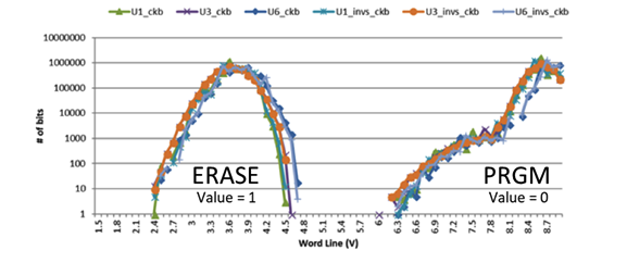
Figure 1: Good cell‑margin separation data for flash memory after programming and erasing. (Source: Adesto)
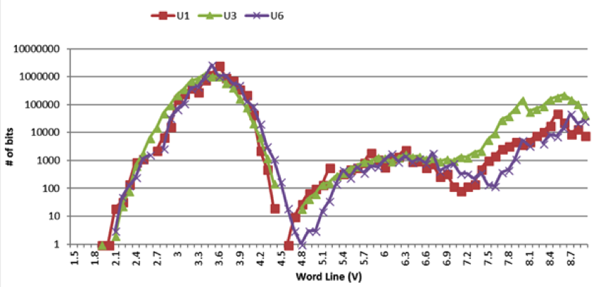
Figure 2: Poor cell‑margin separation data for flash memory affected by significant SPI line noise. (Source: Adesto)
Multiple factors contribute to noise level: operating frequency, signal amplitude, MCU drive strength, and the energy in noise spikes. PCB layout and signal crosstalk also play a role.
Figure 2 illustrates how excessive overshoot and undershoot on the serial interface degrade performance. Figure 3 shows a typical trace where overshoot spikes produce a peak‑to‑peak voltage of 5.65 V—exceeding the absolute maximum specified for the flash memory (Source: Adesto).
click for larger image
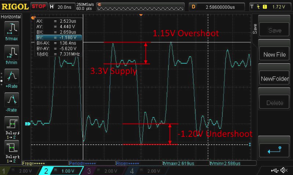
Figure 3: Trace showing overshoot/undershoot on the SPI lines, exceeding the flash memory’s absolute maximum voltage.
Because the noise induced erroneous device operation, errors appeared in the stored flash values. Initial polling of the STATUS register at a lower frequency masked the problem, leading designers to incorrectly attribute the failure to the memory itself.
Identifying the true root cause
Although the fault manifested as a memory failure, Adesto engineers traced the problem to system noise on the SPI bus. While an impedance mismatch on the PCB track between the MCU and flash contributed, it was not the sole factor.
The culprit turned out to be the MCU interface, which defaults to a high drive level at power‑up. This excessive drive produced overshoot and undershoot on the SPI lines, sometimes misinterpreted as legitimate transitions and causing read/write errors. In this case, the overshoot’s energy also disrupted the flash’s charge pump, creating the observed errors.
The customer’s microcontroller offered a configurable I/O drive current that defaulted to HIGH on startup. Because the application code never changed this setting, the high drive persisted during normal operation.
Other devices on the SPI bus may have tolerated the excess drive, but flash memory’s sensitivity—especially its high operating frequency and charge‑pump requirement—made it vulnerable. The result was intermittent failures that were initially mistaken for a fault in the flash device.
Correcting the error
By reducing the drive current via firmware, the overshoot and undershoot were effectively eliminated (Figure 4), restoring error‑free operation of the flash memory.
click for larger image
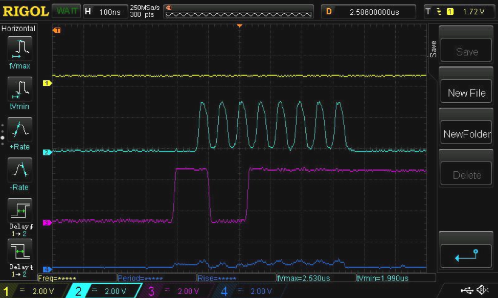
Figure 4: With no overshoot, the flash charge pump operates correctly, ensuring reliable functionality. (Source: Adesto)
The flash device’s internal compensation mechanisms managed to mitigate the effect of the noise, but the solution lay in correcting the root cause: the MCU’s default drive strength.
This case underscores a critical lesson: what appears as a genuine component failure can actually be an oversight in design. Replacing the memory would have been a natural but costly response; instead, collaboration between the customer, supplier, and engineering teams uncovered the true cause and applied the right fix. The outcome was a markedly improved design, higher system performance, and greater reliability.
Conclusion
System noise can often be dismissed when no visible impact occurs, yet intermittent errors are notoriously difficult to diagnose. Misinterpreting these errors only compounds the challenge.
Overshoot, though subtle, can have significant consequences. Flash memory depends on a meticulously engineered interface; excessive noise on the serial bus can propagate to the charge‑pump circuitry, degrading programming and erase operations. The resulting artifacts may be wrongly attributed to the memory device itself.
In this example, assuming the flash memory was at fault could have led to products that failed later. By adjusting the MCU drive strength, programming and erase consistency improved dramatically: endurance rose from an unacceptable ~20 k cycles to over 2.5 M cycles with no errors and no need for additional error‑detection routines.
Modern microcontrollers’ configurability is a double‑edged sword—while it can introduce problems like overshoot, it also offers the flexibility to resolve them.
Embedded
- Operating System Fundamentals: Key Components and Functions
- Scaling Serial Additive Manufacturing: How Additive MES Drives Efficiency and Growth
- Winbond’s SpiStack Dual‑Die NOR+NAND Flash Powers NXP Layerscape LS1012A Development Board
- Leveraging Real‑Time Digital Twins to Enhance Logistics Efficiency
- Accelerate Your Digital Supply Chain Transformation with Cloud Analytics
- Prevent Production Downtime: How Contaminants in Compressed Air Impact Processes
- Eliminate Errors & Boost Production Quality with an Effective QMS
- How Small Manufacturing Shops Can Embrace Digital Solutions Cost‑Effectively
- Digital Manufacturing: Strengthening Supply Chains Against Disasters
- Optimizing Fluid Systems: Fabrication Strategies to Reduce Resource Constraints