


Quick Guide: Selecting RF Bypass Capacitors for MMICs
Supply‑line noise is a persistent challenge in RF systems, especially when high‑frequency MMIC amplifiers deliver broadband gain. Even a few nanovolts of unwanted noise can mix with the desired signal, lowering the signal‑to‑noise ratio and generating spurious harmonics.
To keep the amplifier’s performance pristine, RF designers rely on a bypass capacitor that shunts RF energy to ground before it reaches the gain stage (see Figure 1).
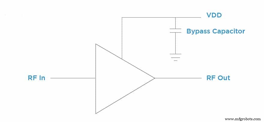
Figure 1. Bypass capacitor in shunt to the gain‑stage supply line.
A truly broadband filtering solution is essential because MMICs designed for military or defense applications often operate well beyond 20 GHz. This requires careful selection of a capacitor that maintains low impedance across the entire operating band.
Most high‑frequency MMICs are fabricated using a wire‑bond process rather than surface‑mount. Consequently, the bypass capacitor must be wire‑bondable, offer sufficient capacitance at the required supply voltage, and fit within the tight space constraints of the MMIC package.
Placement is equally critical: the capacitor should sit on the ground plane as close as possible to the MMIC device. Depending on the target bandwidth, designers typically employ one or two microwave capacitors. A common pair is a 100 pF Border Cap® positioned directly next to the MMIC, followed by a 10 nF V‑Series capacitor as a second stage (see Figure 2).
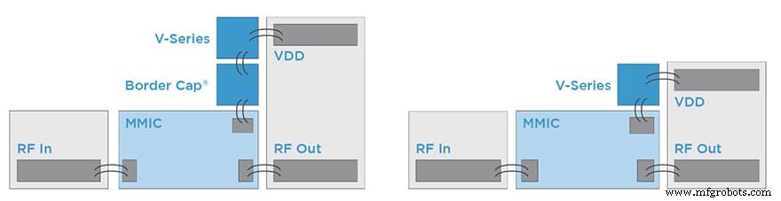
Figure 2. Example configurations: single‑cap and dual‑cap layouts.
Choosing the right capacitor, however, is not a purely theoretical exercise. The board must be tested under real‑world conditions, evaluating the impedance of the device across the entire frequency range of interest. In practice this means measuring the RF isolation of the capacitor when mounted in shunt on a test board (see Figure 3 and Figure 4).
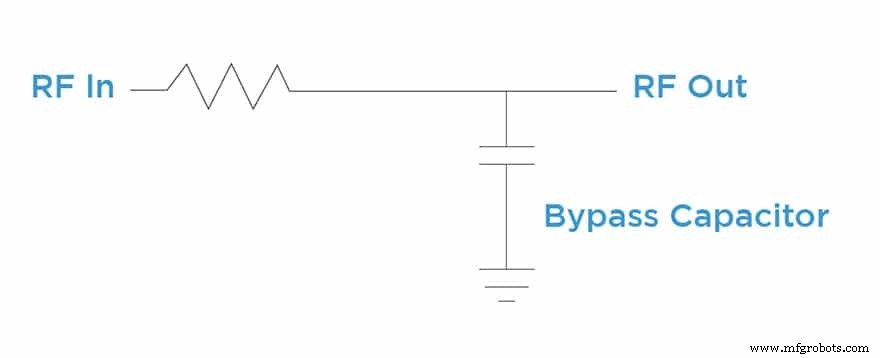
Figure 3. Capacitance in shunt to a line.
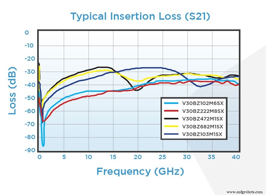
Figure 4. RF isolation of the Knowles V‑Series capacitor measured in shunt.
In summary, the optimal bypass capacitor for an MMIC must not only fit mechanically and electrically but also deliver a clean, low‑impedance path that eliminates supply‑line noise across the full operating spectrum. Thorough on‑board testing and adherence to proven component families, such as Knowles Precision Devices’ Border Cap® and V‑Series, help guarantee robust RF performance.
Figures and featured image credit: Knowles Capacitors
Internet of Things Technology
- CNC Milling Essentials: A Professional Operator’s Quick Reference Guide
- Total Preventive Maintenance: A Practical Guide to Boost Efficiency & Reliability
- Construction Asset Management: A Practical Guide to Maximize ROI and Efficiency
- Routine Maintenance: A Practical Guide to Extending Asset Life
- Java 8: A Comprehensive Quick Reference Guide
- Choosing the Right PCB Material: A Comprehensive Guide
- Expert Guide to Choosing 3D Printing Materials for SLS, MJF, FDM, SLA & DLS™
- GD&T Parallelism: A Quick Reference Guide
- How to Choose the Right Hydraulic Cylinder: A Comprehensive Selection Guide
- Understanding Power Chucks: A Comprehensive Guide for Precision Machining