


Designing Parabolic, Hyperbolic & Elliptical Reflectors for 3D Printing: A CAD Guide
In this guide, we demonstrate how to design parabolic, hyperbolic, and elliptical reflectors from first principles using any CAD tool.
Applications
Reflectors play a pivotal role in diverse fields—from industrial and stage lighting to antenna signal collection, directional microphones, speaker enclosures, infrared heaters, and ultrasound sensors. By choosing the appropriate conic section—spherical, ellipsoidal, paraboloidal, or hyperboloidal—engineers can tailor performance to the specific application.
Each shape offers unique advantages. For instance, a parabolic reflector focuses rays into a parallel beam when the source is placed at its focal point. This article focuses on designing parabolic reflectors and extends the principles to other conic sections that can be 3‑D printed with additional features.
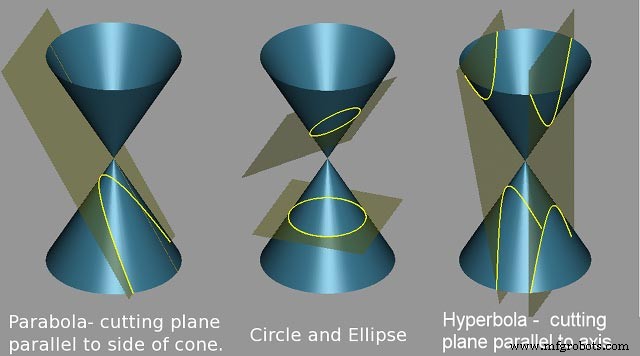
From Equations to CAD
Modeling in Autodesk Fusion 360
Below is a systematic method, derived from first principles, for constructing a parabolic reflector in Fusion 360. This approach was first outlined by Andrew Sears of Autodesk Support and has been refined for clarity.
Start with the key dimensions: the diameter D and the height h. For illustration, let D = 80 mm and h = 30 mm.
Step 1
Draw a right triangle with base D = 80 mm and height 2h = 60 mm. From the midpoint of the base, sketch a line perpendicular to the hypotenuse; this offset distance is measured as 33.282 mm.
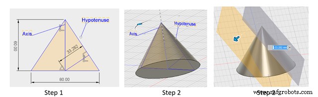
Step 2
Revolve the triangular region bounded by the hypotenuse, base, and the axis of symmetry to create a conical shell. Generate a tangent plane, copy it, and translate it by the offset distance so that it intersects the triangle’s base at the offset line’s endpoint. This plane slices the cone, revealing the desired parabolic profile.
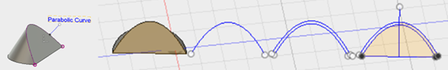
Step 3
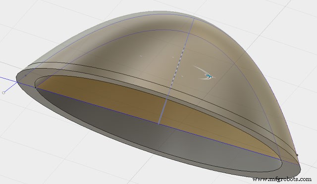
Extract the parabolic curve from the cutting plane, offset it outward by the required wall thickness (e.g., 3 mm), and revolve the resulting profile around the axis. The final solid is a parabolic reflector ready for printing.
From CAD to Prototype
3‑D printing bridges the gap between virtual design and real‑world testing, enabling rapid validation, functional trials, and small‑batch production. During iteration, consider aesthetics, printability, and mounting solutions in collaboration with your chosen printing partner.
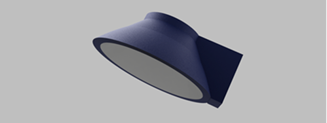
Below is an example of a parabolic reflector integrated with a mounting fixture, illustrating how design and manufacturing can be streamlined.
Stratnel offers design advisory and printing services, empowering designers to accelerate development cycles and realize complex geometries through additive manufacturing.
This article was originally authored by K. Padmanabhan, CEO & Founder of Stratnel Technologies LLP, and republished with their permission.
3D printing
- Design for Manufacturability: A Practical Guide for Engineers and Designers
- Key Design Principles for Optimizing Metal 3D Printed Parts
- 4 Key Design Principles for Successful 3D Printing
- Mastering 3‑D Print Orientation: Tips for Surface Finish, Strength, and Support Efficiency
- 3D Printing: Transforming Everyday Life Through Rapid Design, Production, and Repair
- Cut Print Time for 3D‑Printed Plastic Parts – Expert Design Strategies
- Design for Additive Manufacturing (DfAM): 3D Printing Strategies That Cut Costs and Boost Efficiency
- Step‑by‑Step Guide: Convert STL to G‑Code for Reliable 3D Printing
- Step-by-Step Guide to Creating STL Files for 3D Printing
- Expert Design Tips for Carbon DLS™ 3D Printing Success