


Mastering 3‑D Print Orientation: Tips for Surface Finish, Strength, and Support Efficiency
Choosing the right orientation for a 3‑D print is a pivotal step in achieving a functional, high‑quality part. With Stratasys systems that employ soluble support material, virtually any angle can print successfully, but that freedom also demands a deliberate strategy. Depending on the part’s geometry, you may prioritize a pristine surface, directional strength, or reduced support usage to cut time and cost.
Below, I walk through three representative models—an end‑use slider, a prototype airfoil, and a tooling jig—showing how to balance finish, strength, and support for each application. This guide assumes a basic grasp of FDM 3‑D printing and familiarity with your printer.
Example 1: End‑Use Slider
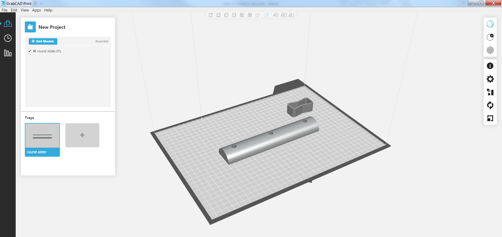
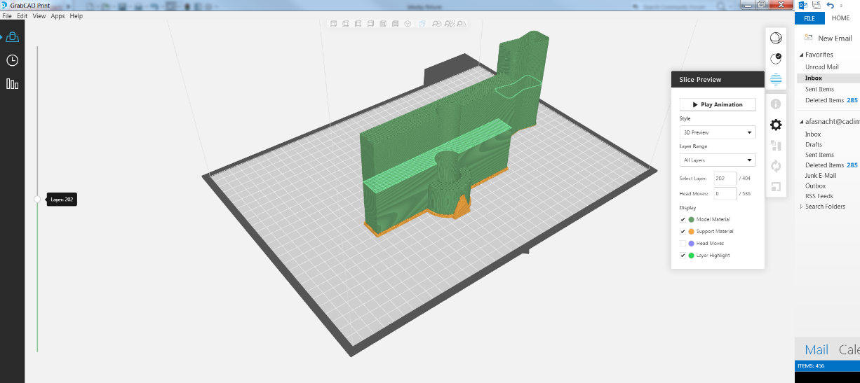
Sliding components often rely on plastic bushings or nylon contact surfaces, such as in furniture drawers. I modeled a half‑circle slider with mounting holes to illustrate orientation choices.
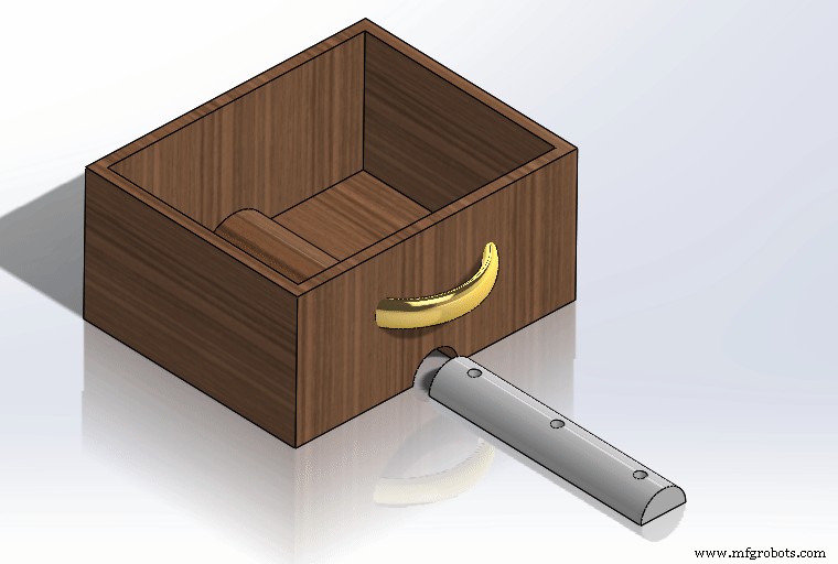
For an end‑use part, the optimal orientation places the rounded contact face horizontal. This positioning delivers the best surface finish on the sliding surface, preserves structural integrity for the mounting holes, and minimizes support material and post‑print cleanup.
Alternative orientations can improve the finish on other faces but introduce trade‑offs:
- Surface‑first orientation: Positioning the desired face flat yields a smoother finish for that area but creates layer lines along the slider’s motion path and increases support around the mounting holes.
- Flat‑first orientation: Orienting the flat face upward improves its finish but results in a rougher rounded surface and requires more support, increasing post‑processing effort.
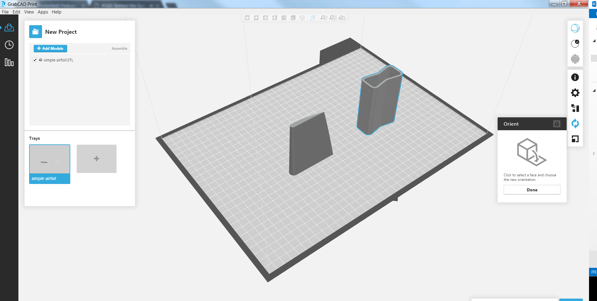
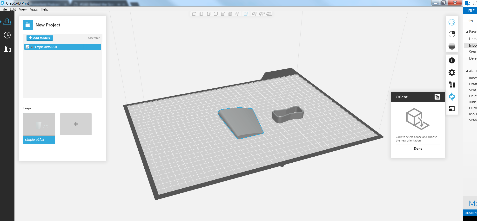
Example 2: Prototype Airfoil
Airfoils are complex geometries that benefit from careful orientation when prototyping. I designed a simple airfoil to demonstrate the trade‑offs between surface finish, strength, and support.
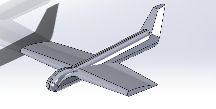
The chosen orientation places the most critical smooth surfaces—such as the upper camber—parallel to the build plate. This yields a near‑perfect finish and limits support usage. However, the inclined top surface can appear stepped due to the layer stack.
Alternatively, aligning the airfoil’s main load direction (lift) perpendicular to the layer planes enhances structural strength at the expense of a slightly rougher surface.
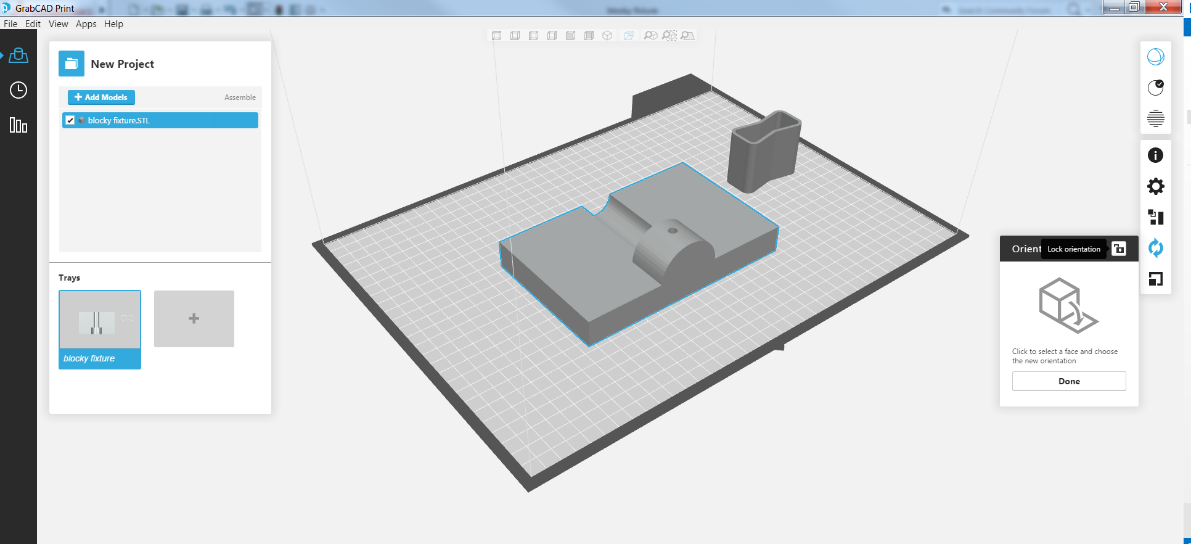
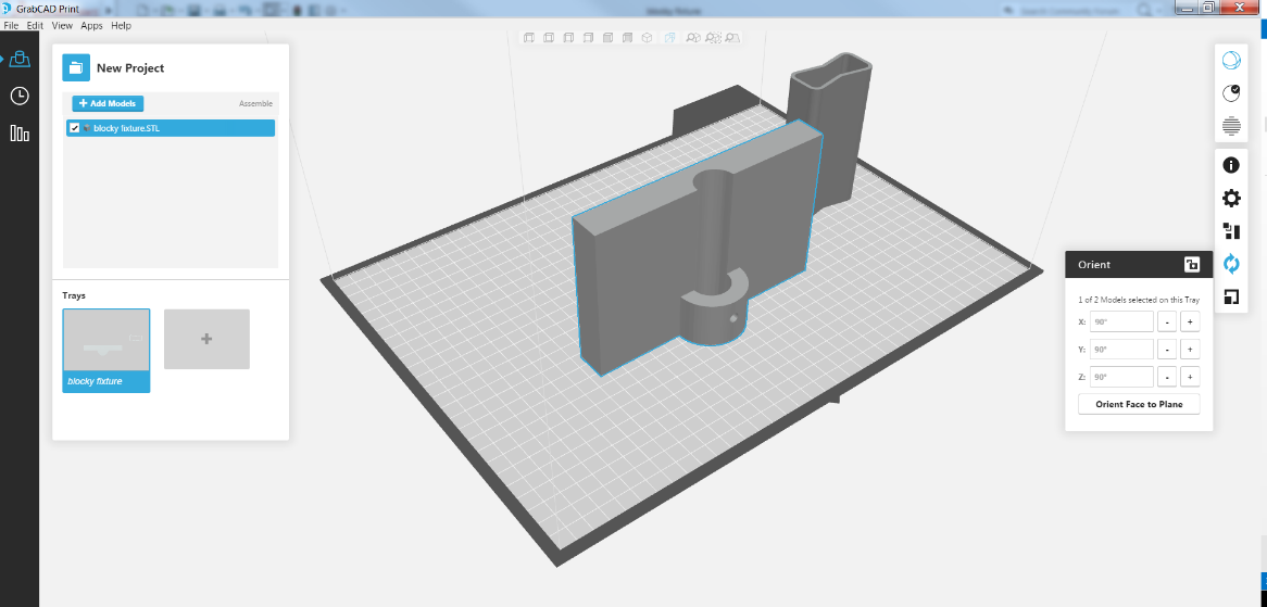
Example 3: Tooling Jig
For a jig that clamps a pipe and drills a hole through its end, strength dominates. I designed the jig to illustrate how orientation can reinforce critical load paths while balancing support.
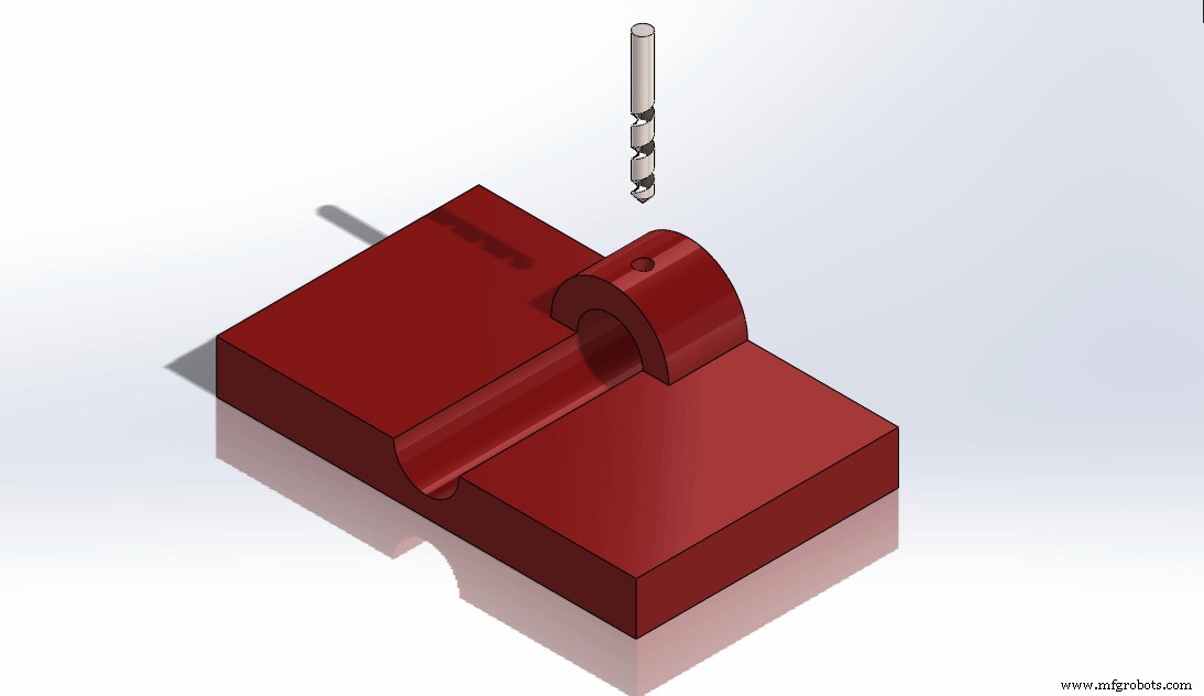
The preferred orientation aligns the layers perpendicular to the clamp forces, providing a robust build even though it consumes a modest amount of support. This choice also offers a tidy surface finish on the top face.
A support‑minimal orientation would reduce print time but compromise the jig’s strength and the finish on key faces, making it less suitable for functional use.
Choosing the right orientation often feels like art, but grounding your decision in the part’s priorities—surface finish, strength, or support economy—guides you toward the optimal setup.
Tags: 3D Printing, End‑Use Part, Positioning, Prototype, Tooling Jig
3D printing
- How MES Software Can Revolutionize Production Planning for Your 3D Printing Service
- Effortless Post‑Processing for FDM 3D Prints
- 3D Printing: From Rapid Prototyping to Full‑Scale End‑Part Production
- Persuading Your CFO to Embrace Automation: A Strategic Guide (Part 3)
- Mastering CFO Advocacy: Structuring Your Automation Pitch (Part 2)
- How to Persuade Your CFO to Invest in Automation: A Strategic Guide
- Step‑by‑Step Guide: Convert STL to G‑Code for Reliable 3D Printing
- Step-by-Step Guide to Creating STL Files for 3D Printing
- Determining if Your Part Is Ideal for 3D Printing: A Comprehensive Guide
- Revolutionize FFF 3D Printing with Soluble Filament Supports