


Embedding Nuts in 3D Printed Parts to Achieve Industrial‑Grade Fastener Strength
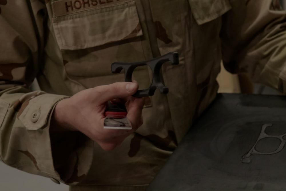
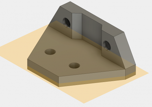
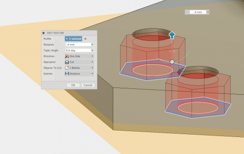
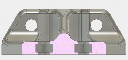
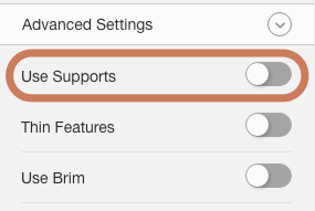
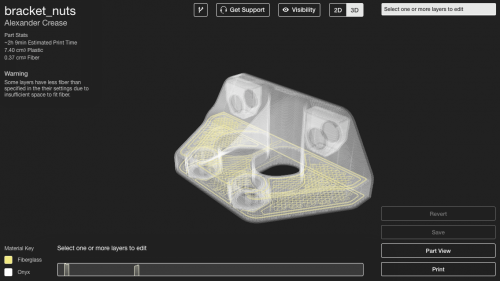
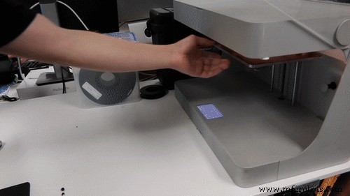
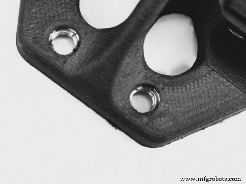
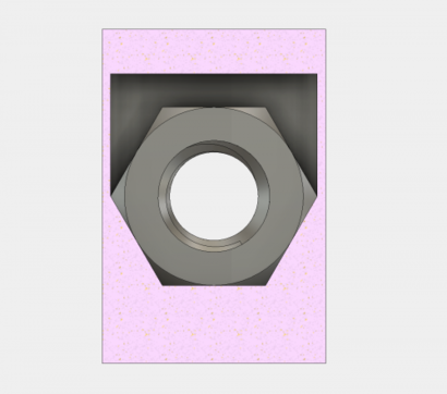
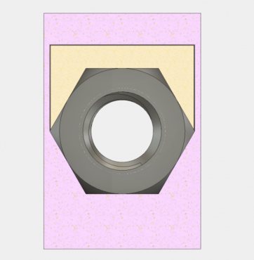
Most 3D‑printed plastics struggle to produce reliable threaded or tapped holes, especially in undersized cavities. Their intrinsic material yield strength lags behind that of conventional metal fasteners, and the minuscule dimensions of threads often push the limits of typical consumer‑grade printers. Even when fiber‑reinforced polymers such as the Mark Two or X7 are used, the reinforcement fibers do not substantially increase thread strength because they are too small to affect the thread geometry. In contrast, metal threads are inherently more precise and deliver more dependable engagement. Read our newest customer success story about a major training base for the U.S. Army. While heat‑set threaded inserts can add metal to a plastic part and reflow the surrounding material for increased strength, they come with design limitations. The insert must sit flush on the part surface, and its pull‑out strength cannot exceed the surrounding plastic’s material properties. Overprinting—or co‑processing and embedded printing—offers a practical alternative. The concept mirrors over‑molding in injection molding: a component is placed inside the mold, and plastic is cast around it. In 3D printing, you pause the build, insert the component, and resume, effectively encapsulating it within the printed structure. By embedding nuts into 3D‑printed parts, you create hidden, industrial‑grade bolt connections that exceed the performance of conventional inserts. The additional material between bolt and nut, coupled with optional fiber reinforcement, yields a stronger, more reliable joint. The process involves designing a cavity the size of the nut, pausing the print before the cavity’s top layer, inserting the nut, and continuing the build. 1. Designing the Cavity – Measure the nut’s dimensions with calipers and sketch a cavity centered on the bolt hole. Add ~0.05 mm clearance on each side (total +0.10 mm) to ensure a secure fit. For example, an M5 hex nut measured at 7.85 mm × 3.85 mm becomes an 8.0 mm × 4.0 mm cavity after rounding. Extrude the sketch to the desired cavity depth. Avoid chamfers or fillets inside the cavity, as they can hinder nut insertion. 2. Adding a Pause – In Eiger, enable the “pause after layer” option just before the cavity’s top layer. Disable supports unless absolutely necessary (Advanced Settings). 3. Adding Fiber – Reinforce the sections adjacent to the cavity with fiber. Layer the fiber on the sides of the nut or on the walls of the cavity to increase pull‑out strength. 4. Printing the Part – Start the build. When the pause triggers, insert the nut (and optional secondary part, if needed), optionally apply a thin layer of build‑plate glue to the top face to improve adhesion, then resume. 5. Managing Supports and Complex Geometries – If supports are required, remove them with needle‑nose pliers during the pause. For cavities with non‑flat ceilings, consider using angled overhangs or a secondary part to provide a flat insertion surface. Embedding nuts on non‑XY planes requires a secondary feature that offers a flat top for the print head. For instance, to embed a hex nut with its axis parallel to the build plate, design a secondary part that fills the cavity above the nut, leaving a slight clearance. Print the secondary part and the main component together. When the build pauses, insert both the nut and the secondary part, then resume so the nozzle prints over the flat top of the secondary piece. Using this technique, you can embed nuts at any angle and on any plane, opening new possibilities for complex assemblies. Feel free to experiment and share your findings on Twitter, Facebook, or Instagram!U.S. Army Case Study
Overview
Design Guidelines
Embedding Nuts in the XY Plane
Printing Secondary Parts to Embed Nuts on Other Planes
3D printing
- Metal Plating for 3D Printed Parts: A Practical, Expert Guide
- 3D‑Printed Drone Enables Rapid, Cost‑Effective Data Collection in Antarctica
- MMF #5: Mastering Component Embedding in 3D‑Printed Parts with Markforged Printers
- Modular Precision Printing Solutions for Automotive & Aerospace
- Scheurer Swiss Delivers 3D‑Printed Carbon‑Fiber Engine Parts for Toyota FT‑60 Racing Car
- Guaranteeing Dimensional Accuracy in 3D Printed Parts
- Are 3D Printed Parts Really Strong?
- 10 Proven Water-Resistant Solutions for 3D Printed Parts: Materials & Post-Processing
- Advanced Inspection Strategies for 3D Printed Engine Parts – Part 3
- Expert Guide to Polishing Metal Parts in 3D-Printed Medical Devices