


MMF #5: Mastering Component Embedding in 3D‑Printed Parts with Markforged Printers
Markforged Mechanical Features (MMF) is a series of posts that distill proven best practices for designing conventional engineering components and mechanical features optimized for composite‑reinforced 3D printing on Markforged machines.
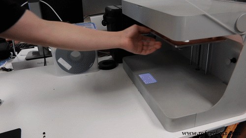
Last week we showed how overprinting nuts can create robust connections in industrial‑strength parts. This entry extends that concept by demonstrating how to embed distinct components—or even different materials—directly into a print. The technique is straightforward: begin the print, pause at a predetermined layer, insert the component, and resume. The printer will then build over the embedded piece.
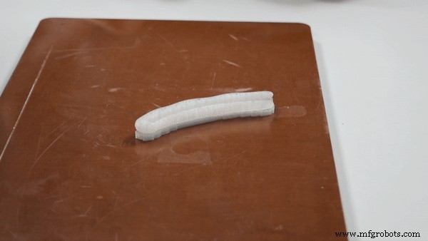
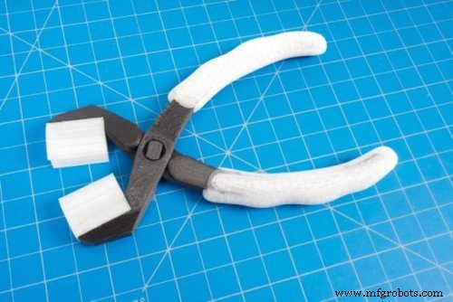
Embedding is ideal for integrating electronics, creating multimaterial parts, or prototyping high‑cost components before committing to large‑scale manufacturing. To illustrate, I designed a pair of 3‑in‑1 pliers featuring a stiff Onyx body with fiberglass reinforcement and ergonomic nylon grips.
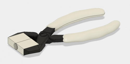
In this design, the pliers’ jaws are printed from Onyx, while the grips—fabricated from a tough nylon—are inserted during the pause. The result is a tool that feels solid yet comfortable.
Embedding works the same way a design for assembly does: you must create a cavity that accommodates the part you’ll insert. Here’s a step‑by‑step guide for modeling and printing with embedded components.
Designing the Cavity
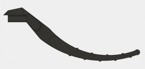
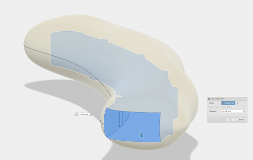
Start by selecting the build face that will expose the cavity’s top surface. For the pliers, the cavity resides on the underside of the grips. Create the void by subtracting the embedded part from the host geometry—ensuring the cavity’s roof is flat. If the embedded piece has chamfers or fillets, remove them; the printer needs a level surface to rest on.
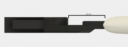
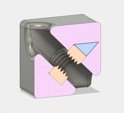
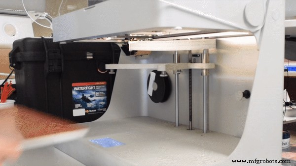
Next, verify that no portion of the embedded component extends above the cavity ceiling or too close to the extruder head. On the Mark Two, the nozzle sits roughly 35 mm from the front of the print head. Parts that protrude within this zone risk collision. Position the cavity so the embedded piece projects toward the printer’s front, keeping the top clearance above 35 mm.
After subtracting, apply a tolerance offset of approximately 0.08 mm on all cavity surfaces. This buffer guarantees a flush fit when the print resumes, preventing layer adhesion issues or mechanical interference.
If the cavity roof is irregular, consider adding a secondary insert that conforms to the embedded part’s top geometry. This strategy, detailed in our previous nuts‑overprinting post, ensures a secure fit. Otherwise, angling the roof slightly above the component can work, but may leave the part slightly loose.
When possible, avoid support material to keep the cavity clear. If supports are unavoidable—such as for complex grip geometries—remove them before inserting the component; the Markforged build plate’s kinematic coupling makes removal hassle‑free.
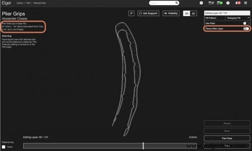
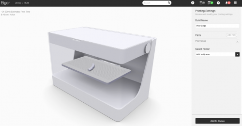
Inserting Pauses in Eiger
Open Eiger’s internal view and add a pause just before the layer that begins the cavity roof. Note the expected pause duration to time your intervention accurately. Disabling supports is recommended if your design doesn’t require them; if you do need supports, they can be removed once the print has paused.
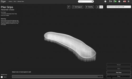
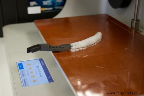
Position your model on the build plate so you can reach the cavity quickly. For the pliers, the cavity sits near the front, allowing rapid insertion of the jaw assembly.
Adding the Component
Timing is critical. The Markforged printer is a FFF machine: the filament heats, extrudes, and then cools, causing slight shrinkage. If the pause is too long, the previous layer may lose adhesion, weakening the print. Work quickly—ideally within the pause window you noted in Eiger.
When the cavity requires supports—like the complex grip bottom—remove them immediately after the print pauses and before inserting the part. The kinematic build plate then returns to its original position, ready for the resumed print.
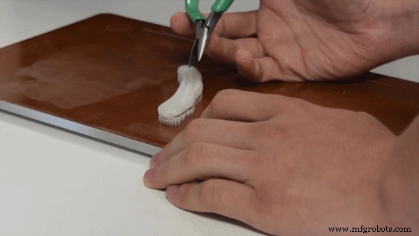
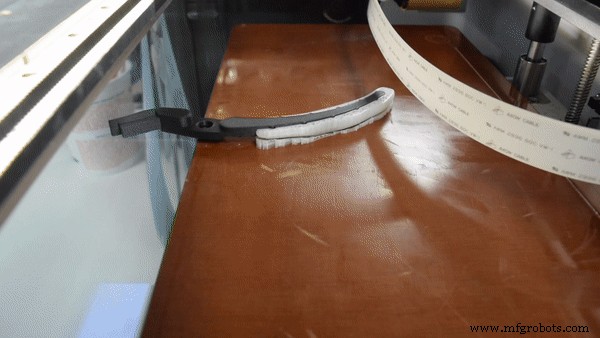
Insert the component flush with—or slightly below—the paused layer. A raised part can cause the print head to jam or the filament to clog, ruining the print.
Once the part is seated, resume the print. The Markforged’s build plate will lock back into place automatically, and the printer will continue depositing material over the embedded piece.
If the embedded part isn’t a Markforged print, apply a thin layer of the printer’s standard build‑plate adhesive to the cavity’s top surface before insertion. This adhesive enhances adhesion between the nylon grip and the underlying structure.
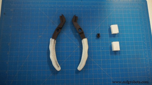
After printing two pliers and installing a small pin at the joint, the final result is a functional tool with interchangeable jaws and ergonomic grips—fully integrated in a single build.
Files for download:
Pliers and pin MFP (Onyx + fiberglass)
Grips MFP (Nylon)
Custom JAW MFP (Nylon)
Pliers STL
Pin STL
Grip STL
Custom Jaw STL
Other Applications
Overprinting unlocks a wide array of possibilities: from fully integrated electromechanical assemblies to multimaterial prototypes and overmolded parts. Whether you’re embedding hidden nuts, bearings, or electronics, the same cavity‑design principles apply. Share your own projects on Twitter, Instagram, or Facebook to join the community.
3D printing
- Metal Plating for 3D Printed Parts: A Practical, Expert Guide
- In‑Process Inspection: Elevating 3‑D‑Printed Part Quality
- 3D‑Printed Drone Enables Rapid, Cost‑Effective Data Collection in Antarctica
- Professional Guide to Finishing and Painting 3D Printed Parts
- Optimizing 3D Printed Part Strength with Efficient Fiber Routing – Part 1
- Embedding Nuts in 3D Printed Parts to Achieve Industrial‑Grade Fastener Strength
- Guaranteeing Dimensional Accuracy in 3D Printed Parts
- Enhancing the Strength of 3D Printed Parts: Proven Techniques
- Advanced Inspection Strategies for 3D Printed Engine Parts – Part 3
- Mastering Machined Part Design: A Comprehensive Guide