


MarkForged Mechanical Features #1: Mastering 3D Printed Living Hinges
Update: Dive deeper into flexural design by watching our webinar on designing flexural elements and living hinges.
Original Post: MarkForged Mechanical Features (MMF) is a series of in‑depth posts that share best practices for designing common engineering parts and mechanical features for composite‑reinforced 3D printing with MarkForged printers.
Welcome to the inaugural edition of MarkForged Mechanical Features! Customers routinely ask how to translate familiar mechanical features into 3D printed parts that fully leverage the functional strength of MarkForged materials. To help share this knowledge, we’ll publish regular articles on a single engineering feature, offering practical tips and tricks for maximizing your MarkForged printer’s potential.
Today we explore living hinges. In essence, a living hinge is a thin, integral part that bends to provide rotation around a single axis. You’ve probably seen them on everyday items—from floss container tops to shampoo bottle caps. Their durability and ease of manufacturing make them a staple in injection‑molded packaging, and with MarkForged you can embed them into your designs with industrial‑grade strength.
Tech Terms – if you’re already comfortable with living hinges, feel free to skip this section
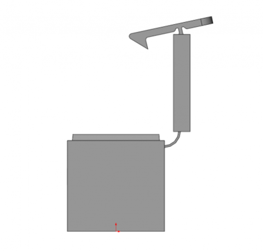
Let’s start with some basics. Below is a labeled diagram of a sample living hinge part that we’ll discuss.
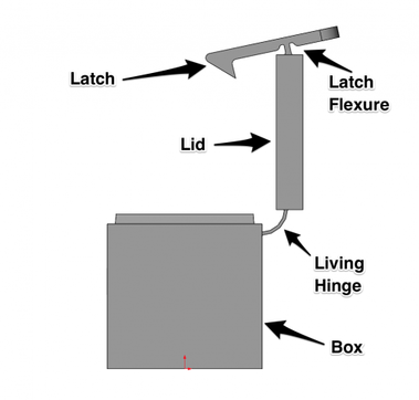
The image highlights two flexible features: the living hinge and the latch flexure. While both allow single‑axis rotation, they serve distinct functions, reflected in their geometry.
To illustrate 3D printed living hinges, I partnered with Bennett, a Senior Mechanical Engineer at MarkForged. Bennett spent three years designing electro‑mechanical systems and injection‑molded casings at a major medical robotics firm, and he’s a SolidWorks virtuoso with a passion for bringing rigorous mechanical design to 3D printing. He’s recently been crafting living hinges in the office.
Bennett: I began printing living hinges after my brother—an engineer in the Bay Area—asked me to prototype his designs on the Mark Two. His work in consumer electronics relies heavily on snaps and hinges. SLA prototypes are great for visualizing form and fit but are brittle and fail after a single use, making them unsuitable for functional testing. Traditional injection‑molded prototypes are costly and slow, hindering rapid iteration. My brother sent me the STL files, and I set them up in Eiger to print on a Mark Two that very day.
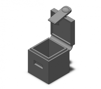
Working on his parts sparked my interest in experimenting with design parameters for Mark Two living hinges. The box below shows a simplified model that incorporates the guidelines I developed during that collaboration.
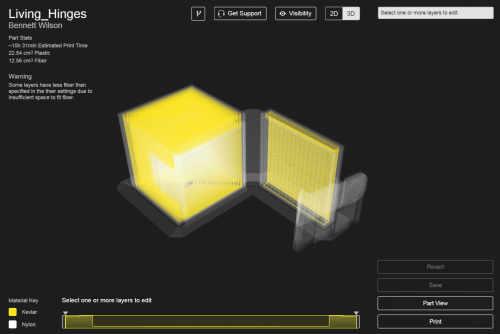
Nick: One of the keys to successful living hinge prints is proper part orientation in Eiger. Whether you use plain nylon (for flexibility) or kevlar‑reinforced nylon (for higher load‑bearing stiffness), the hinge’s side profile must align with the Z axis. In other words, the full side profile should lie flat in the XY plane.
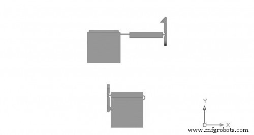
Proper orientation matters because 1) fibers can only be laid in the XY plane, so aligning the hinge allows kevlar to run along its length, and 2) as‑printed nylon tensile strength in a layer far exceeds inter‑layer adhesion. These factors necessitate the orientation shown in the Eiger screenshot below.
A frequent challenge for new users is grasping the anisotropy of 3D‑printed parts.
Tech Terms
Material anisotropy refers to directionally dependent mechanical properties. For example, wood splits easily along grain but resists cutting across it. Isotropic materials, like many metals, exhibit uniform properties regardless of orientation.
/Tech Terms
Bennett: As Nick noted, FFF gives peak strength in the XY plane. Nylon’s fatigue resistance further enhances hinge durability. Therefore, the optimal hinge cross‑section lies in the horizontal XY plane. Thicker hinges increase stiffness. In this example, a lid hinge requires full 180° motion, while a latch hinge needs less rotation but must reliably hold the lid closed. I designed the lid hinge as thin as possible and the latch hinge thicker for stiffness, modeling the lid at a 90° open neutral state and the latch slightly closed to aid snap‑in. Keep in mind that 3D‑printed flexible parts tend to return to their as‑printed state unless they undergo significant plastic deformation.
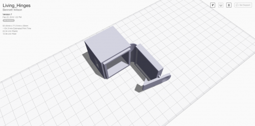
Next, I imported the part into Eiger, rotated it for correct orientation, and enabled fiber. I used a concentric fill to fully embed fiber and applied the settings to the entire part. Eiger flagged insufficient space for fiber due to my hinge dimensions, but the Mark Two’s larger nozzle accommodated fiber in both the base and lid—something the Mark One couldn’t achieve with this size. I also enabled the brim setting to support tall, thin sections during initial layers.
Technical Details
- Lid hinge thickness: 0.7 mm for maximum flexibility
- Latch hinge thickness: 1.2 mm for greater stiffness and secure locking
- Parts modeled in both open and closed positions to validate bend radius before final printing
Ready to try it yourself? Download Bennett’s SolidWorks files: Living_Hinges CAD SW file and the Eiger‑ready STL: Living_Hinges STL.
3D printing
- Living Hinges: The Rust‑Proof, Silent, and Customizable Advantage Over Metal
- Living Hinges Explained: Single‑Piece Elastic Joints that Outperform Traditional Hinges
- Coloring 3D‑Printed Parts with Wax Crayons: A Novel Post‑Processing Technique
- Elevating Quality Control: 3D‑Printed Tooling Enhances Manufacturing Precision
- Designing Functional 3D‑Printed Bicycle Pannier Adapters with Kevlar CFF
- Reimagining the Go‑Kart: 3D‑Printed Carbon‑Fiber Parts for Unmatched Performance
- Crafting a Custom 3D‑Printed Steering Wheel for a Go‑Kart: Lighter, Comfortable, and Modifiable
- Webinar: Build Stronger 3D Parts with Eiger Software
- MMF #3: Building Industrial‑Strength 3D‑Printed Hinges with Kevlar‑Reinforced Living Joints
- Professional Guide: Dyeing 3D Printed Polyamide Parts for Vibrant Color and Durability