


The Triode: A Cornerstone of Vacuum Tube Technology
The Triode: A Cornerstone of Vacuum Tube Technology
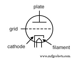
Guglielmo Marconi’s early radio experiments set the stage for the first practical vacuum tubes, the Audion tubes pioneered by Lee de Forest. De Forest’s Audion earned the moniker triode because it contained three key components: a filament (electron source), a grid (control electrode), and a plate (anode). In contrast, the simpler diode contained only a filament and a plate.
Early triodes used the filament itself as the electron emitter, but this approach had two significant drawbacks. First, the filament’s resistance caused a voltage drop along its length, leading to inconsistent electron emission and the introduction of unwanted AC noise when the filament was powered by alternating current. Second, the filament’s limited surface area capped the maximum current the tube could conduct.
To overcome these limitations, manufacturers adopted an indirectly heated cathode—a thin metal cylinder that enveloped the twisted filament. The filament supplied heat to the cathode, which then emitted electrons without carrying the heating current itself. The classic triode symbol for an indirectly heated cathode looks like this:
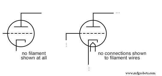
For simplicity, many diagrams omit the filament or show it without a power connection:
Basic Amplifier Operation
Below is a classic single‑stage triode amplifier circuit:
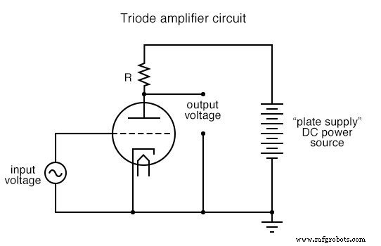
In this configuration, a low‑voltage AC signal applied between the grid and cathode modulates the electron flow from cathode to plate. The grid’s alternating voltage “throttles” the high‑voltage DC supply, producing a corresponding AC voltage on the plate‑cathode output. Because the grid’s voltage swings are tiny compared to the plate’s voltage, the triode acts as an efficient amplifier of the input signal.
Non‑Linearity and Harmonic Distortion
The relationship between grid‑cathode voltage, plate‑cathode voltage, and the resulting plate current is inherently nonlinear. As the grid voltage varies, the plate current does not change proportionally, especially when the plate voltage simultaneously shifts due to the same current flow. This nonlinearity distorts the output waveform, adding harmonics that deviate from the original input shape.
Stray Capacitance and High‑Frequency Challenges
Every pair of conductive surfaces separated by a vacuum forms a tiny capacitor. In a triode, the most significant capacitance exists between the grid and plate, as illustrated below:
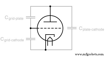
Although the capacitance is small, its reactive impedance becomes critical at radio frequencies, where the stored energy can interfere with signal integrity. These high‑frequency limitations spurred further refinements in tube design, such as adding a screen grid to create a tetrode, thereby reducing grid‑plate capacitance and improving performance.
Industrial Technology
- From Edison’s Lamp to the Audion: The Early Evolution of Vacuum Tubes
- Pentodes: The Fifth Element for Enhanced Tube Performance
- Discover the Crippa Tube Bender: Italy’s Leading Tube Bending Innovation
- A Comprehensive Guide to Tube Bending Techniques
- Precision Tube Bending for Aerospace Excellence
- Tube Bending Mastery: Techniques, Applications, & Industry Standards
- Choosing the Right Small-Bore Tube Fittings: A Comprehensive Guide
- Professional CNC Tube Bending Machine: Precision & Efficiency
- Selecting the Ideal Tube Tester: A Comprehensive Guide
- Precision Tube Roller Benders for Industrial Flexing