


Precision Sheet Metal Enclosure Design: Expert Guide to Bending & Hole Placement
Designing a custom sheet‑metal enclosure is more complex than it appears on screen. A flange that is two millimetres too narrow, a ventilation slot positioned too close to a bend line, or a missing bend relief can all lead to warped panels, failed IP seals, and costly rework.
This guide details the key decisions that most significantly affect enclosure quality: bend geometry, hole placement, and the common design errors our engineers spot during CAD reviews.
Key Functional Requirements of Sheet Metal Enclosures
Before delving into geometry principles, understand why enclosures demand higher precision than generic sheet‑metal parts. A quality enclosure must satisfy:
- IP‑rated sealing (e.g., IP54, IP65): requires tight, gapless seams at every corner. Bend accuracy directly influences seam integrity.
- EMI shielding: small panel gaps can compromise electromagnetic confinement in industrial electronics housings.
- Structural rigidity: panels must withstand component load and repetitive door or cover cycling.
Each requirement hinges on bending precision and hole location. A 1–2° deviation can open seam gaps; a hole too close to a bend distorts the flange and prevents a flush fit. These are functional specifications, not merely fabrication preferences.
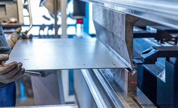
Essential Sheet Metal Bending Design Guidelines
Successful enclosure fabrication depends on two design choices: selecting the correct radius for the material and sizing flanges to avoid post‑forming instability. Mastering both mitigates structural and assembly issues downstream.
Mastering the Bend Radius for Different Materials
The interior bend radius is often misunderstood. A radius that is too tight splits the outer surface; a radius that is too generous compromises dimensional control.
For aluminum, a starting point of 2× the material thickness is typical. For mild steel, 1.5× the thickness is common. Actual minima depend on temper, thickness range, and available tooling.
Special attention is needed for 6061‑T6 aluminum. Its work‑hardening during forming means a radius below 1.5–2T can cause cracking at enclosure corners, even if other alloys tolerate tighter bends. Stainless steel (304/316) exhibits even stronger work‑hardening; a 1.5–2T radius is a practical safety margin.
Validate your radius against the fabricator’s press‑brake tooling library before finalizing corner geometry. A radius that requires non‑standard tooling will increase lead time regardless of feasibility.
Designing Stable Flanges and Mounting Edges for Enclosures
Flange width is frequently under‑specified. A narrow flange triggers a cascade of issues:
- Panel rigidity: short flanges flex under lateral strain, causing rack in control boxes and industrial PC housings.
- Screw mounting: adequate material is needed for clearance holes and an edge distance of roughly 2× the hole diameter.
- Cover and door alignment: panel‑mount connectors or hinged doors are sensitive to flange flatness.
- Assembly clearance: tight inner flanges can clash with mounting hardware for PCBs or internal wiring.
Industry guidelines recommend a minimum flange width of 4× the material thickness for most materials. Larger flanges are justified for load‑bearing side panels or cabinets requiring additional strengthening bends.
Holes and cutouts add geometry that the metal must navigate during shaping. If a feature sits too close to a bend line, plastic deformation pulls the material, distorting the hole and the surrounding panel.
Keep cuts outside the bend deformation zone to preserve structural integrity and avoid flush‑mount issues, especially for connectors or ventilation arrays. The Sheet Metal Design Handbook recommends:
- Standard holes: minimum distance = 2.5T + R (T = thickness, R = bend radius). Some manuals allow 2T+R for holes <1”, but 2.5T+R eliminates out‑of‑round errors.
- Long slots and cutouts: minimum distance = 4T + R. The free edge of a long slot is a key stress concentrator; closer spacing usually produces a wavy panel face.
Design tip: If space is limited and a cutout must be adjacent to a bend line, insert a relief cut or notch across the bend line before forming.
Common Enclosure Design Mistakes Engineers Should Avoid
From our frequent CAD reviews, the most common issues are:
| Mistake | Fix |
|---|---|
| Inconsistent wall thickness across panels | Use a single gauge throughout; mixed thicknesses require separate tooling setups and increase cost. |
| Missing bend reliefs at corner intersections | Add a relief notch (width ≥ 1T, depth ≥ T + R) wherever two bend lines meet to prevent tearing during forming. |
| Holes inside the deformation zone near bends | Follow the 2.5T + R minimum for holes; 4T + R for slots. |
| Ignoring surface‑finishing allowances | Powder coating: typical thickness 60–80 µm per coat. Type II anodizing: 5–25 µm. These affect thread engagement and mating fits if not accounted for. |
These guidelines are baseline values; adjust them for specific part requirements.
Ready to Elevate the Quality of Your Metal Enclosures?
Good enclosure design is a collaboration between design intent and manufacturing reality. The most reliable enclosures aren’t the most complex—they’re the ones where every bend radius, hole clearance, and flange width is thoughtfully planned with production in mind.
Our engineering team evaluates all CAD files for Design‑For‑Manufacturing (DFM) concerns to optimize the part before production. Upload your CAD files or contact JTR’s engineering team for a free manufacturability review and custom material selection. For project requirements, contact us today.
FAQs
Q1: What is the minimum distance between bends in sheet metal?
A1: Keep parallel bend lines at least 4× the material thickness apart as a practical design minimum for enclosures. Narrower spacing can create tooling interference during forming and may reduce flange stability and dimensional consistency.
Q2: Why do holes deform near bends?
A2: Bending plastically deforms the material in the bend zone, stretching the outer surface and compressing the inner. A hole placed too close—typically within about 2.5× the material thickness plus bend radius—can become distorted as surrounding material flows during forming.
Q3: Which material is best for custom sheet metal enclosures?
A3: For most electronics enclosures, aluminum 5052 is a practical default: it bends cleanly, anodizes well, and keeps weight low. If welded construction, outdoor durability, or higher shielding effectiveness is required, 304 stainless steel is often the stronger choice. Its work‑hardening behavior demands careful attention to bend radius, as stainless cracking failures commonly start at improperly designed bends.
Related Guides
Industrial Technology
- Exothermic Welding Explained: Process, Applications & Benefits
- 5 Essential Considerations for Optimizing Your Analyzer Shelter
- Parallel vs Serial Electrical Signals: How Differential Voltage and Modulation Enhance Reliability
- Top PCB Design Pitfalls Engineers Must Avoid
- Hard Turning: The Key to Precise Machining of High-Hardness Materials
- Streamlining Manufacturing Supply Chains: 7 Proven Strategies for Simplicity and Efficiency
- 10 Proven Logistics & Procurement Strategies to Slash Spending
- Discover the Key CMMS Benefits That Simplify Facility Management
- CNC Aluminum vs Cast vs Forged: Which is Best for Motorcycle Parts?
- Enhancing Polyurethane Conductivity with Conductive Additives