


Parallel vs Serial Electrical Signals: How Differential Voltage and Modulation Enhance Reliability
In the BogusBus system, each of the five signal wires carried a single binary bit: 0 V denoted “off” and 24 V DC represented “on.” Because all bits arrived simultaneously, BogusBus is classified as a parallel network.
Adding binary encoding at the transmitter and decoding at the receiver—so that more resolution can be conveyed over fewer wires—does not change the parallel nature of BogusBus.
Introducing a parallel‑to‑serial converter at the transmitter and a serial‑to‑parallel converter at the receiver transforms the architecture into a serial network.
Serial communication forces us to develop more sophisticated techniques for transmitting data.
Serial data transmits every bit over the same pair of conductors, demanding a higher‑frequency signal to keep pace with the data rate.
Imagine a modified BogusBus that sends 8 bits per update instead of the original 5, still using parallel, binary‑encoded transmission.
The A/D converter on the transmitter side generates a new output every second, resulting in 8 bits per second of data being sent to the receiver.
For example, the transmitter alternates between the outputs 10101010 and 10101011 once per second:
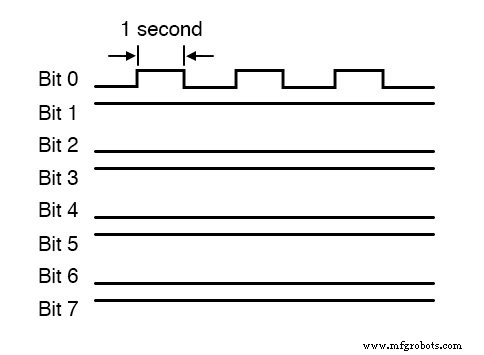
Because only the least significant bit changes, the signal on any given wire varies at a maximum of 0.5 Hz—far below typical communication frequencies.
In contrast, an 8‑bit serial network must transmit all bits sequentially over the single channel within the one‑second window between A/D updates. The resulting waveform would look like this:
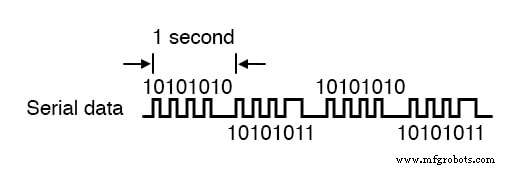
The serial representation now oscillates at roughly 4 Hz—an eight‑fold increase over the parallel case.
While 4 Hz is still benign, scaling to 32 or 64 bits per update at kilohertz update rates pushes the required frequency into the radio spectrum.
Serial data network frequencies enter the radio range, turning simple wires into antennas and transmission lines, with inductive and capacitive reactances affecting performance.
Square‑wave digital signals are equivalent to an infinite series of sine waves with diminishing amplitude and increasing frequency. A 10 kHz square wave is perceived by the line’s capacitance and inductance as a spectrum of higher‑frequency components, so over long runs the waveform degrades.
Bandwidth
When engineers speak of network bandwidth, they refer to the practical frequency limit of a medium. In serial communication, bandwidth equals data volume (bits per word) multiplied by data speed (words per second).
The standard metric is bits per second (bps). The obsolete unit “baud” measures signal level changes per second and is not synonymous with bps, especially when multiple voltage levels encode a single bit.
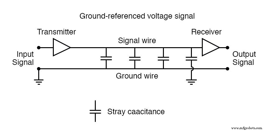
Common Ground Method
The traditional BogusBus design references all bits to a common ground, which is the worst‑case scenario for high‑frequency square‑wave communication. It works well over short distances but becomes problematic when signals travel far.
Differential Voltage Method
A robust alternative is the differential voltage method, where each bit is represented by the voltage difference between a ground‑isolated pair of wires, rather than a voltage to ground.
This approach reduces inductive and capacitive loading and mitigates external electrical interference, extending the practical reach of serial networks.
The differential amplifiers output a voltage between two signal wires, eliminating any ground reference. Only the capacitance between the two signal wires matters, and series capacitances are smaller than individual ones.
Noise induced on both signal wires is ignored because the receiver responds only to the differential voltage.
RS‑232C is a ground‑referenced serial standard suited to short, low‑interference office wiring, whereas RS‑422A uses differential signaling and is common in industrial environments with long runs and high electrical noise.
Despite the benefits, many digital network problems stem from the square‑wave nature of signals. One way to avoid these issues is to modulate a sine‑wave carrier with digital data.
Modulation means that the magnitude of one signal controls some aspect of another. Radio technology has long used amplitude modulation (AM) and frequency modulation (FM) to encode audio onto a higher‑frequency carrier.
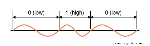
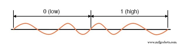
Frequency‑shift keying (FSK) is the digital equivalent of FM. Simple FSK uses two sine waves of distinct frequencies to represent binary 1 and 0:
Because it is difficult to start and stop sine waves exactly at zero crossings, phase‑continuous FSK is often employed. In this scheme, consecutive low‑high and high‑low frequency pairs encode binary states, ensuring each bit takes the same transmission time.
Using sine‑wave carriers mitigates many square‑wave problems, though the modulation and demodulation circuitry is more complex and costly.
RELATED WORKSHEETS:
- Electrical Signal Types Worksheet
Industrial Technology
- Resistor Types Explained: From Potentiometers to Thermistors
- Understanding Network Topologies: From Point‑to‑Point to Ring and Star
- Networks in Embedded Systems: Types, Roles, and Why They Matter
- Validating Neural Networks for Reliable Signal Processing
- Top Carbide Spiral Router Bits for Precision Woodworking
- Electrical Discharge Machines (EDM): Types, Advantages, and Disadvantages Explained
- Electrical Earthing Explained: Methods, Types, and Installation Guidelines
- Comprehensive Guide to Wiring Systems and Electrical Connection Methods
- Motor Protection: Identifying Fault Types & Selecting the Right Devices
- Choosing the Right Drill Bit for Precision Part Manufacturing