


Advanced Tipping Bucket Rain Gauge with Arduino Integration
Components and supplies
 |
| × | 1 | |||
| × | 1 | ||||
| × | 1 | ||||
| × | 1 | ||||
 |
| × | 1 | |||
 |
| × | 1 | |||
 |
| × | 2 | |||
 |
| × | 2 | |||
 |
| × | 1 | |||
 |
| × | 1 | |||
| × | 1 | ||||
 |
| × | 1 | |||
| × | 1 | ||||
| × | 1 |
Necessary tools and machines
 |
| |||
 |
|
About this project
This is a tipping bucket rain gauge, based on rain gauges that are used by professional meteorologists. The device works by funneling rain water onto a tipping bucket which resembles a teeter-totter, with each end having a bucket that hold approx 2 ml of rainwater, When one side fills up, the bucket tips and rainwater begins collecting in opposite bucket. Each time bucket tips, a reed switch is temporarily turned on sending a signal to the Arduino hardware interrupt. The Arduino tracks each bucket 'tip', and converts the 'tips' to rainfall amount (inches of rain), based on volume of bucket and the surface area of the collection reservoir (16.605 sq. in.).
The indoor display unit has a menu select to show 'current hour', 'previous hour', 'current day', and 'previous day' totals.
For each bucket tip, a date stamped event is written to an SD card file. This file can later be imported to Excel for analysis and charting.
Although I do not have a video showing the actual 'bucket tip', this video shows gauge recording actual rainfall event.
Step 1
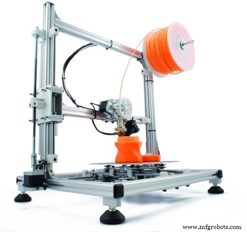
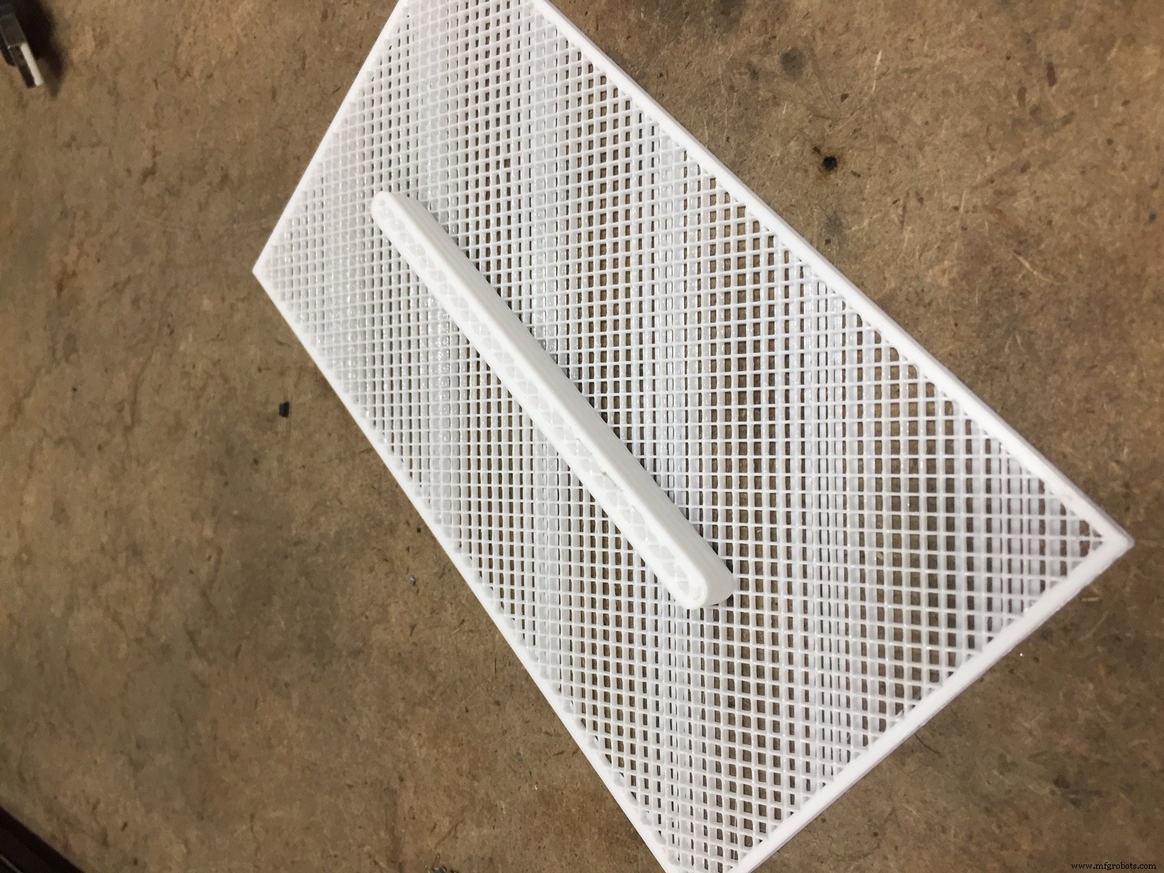
Print all components listed. I used PETG for all components as it is a material that is well suited to UV exposure and temp exposure for outdoor use. For the top filter, make sure to turn off all horizontal shells (top and bottom) to create the porous detail.
Step 2
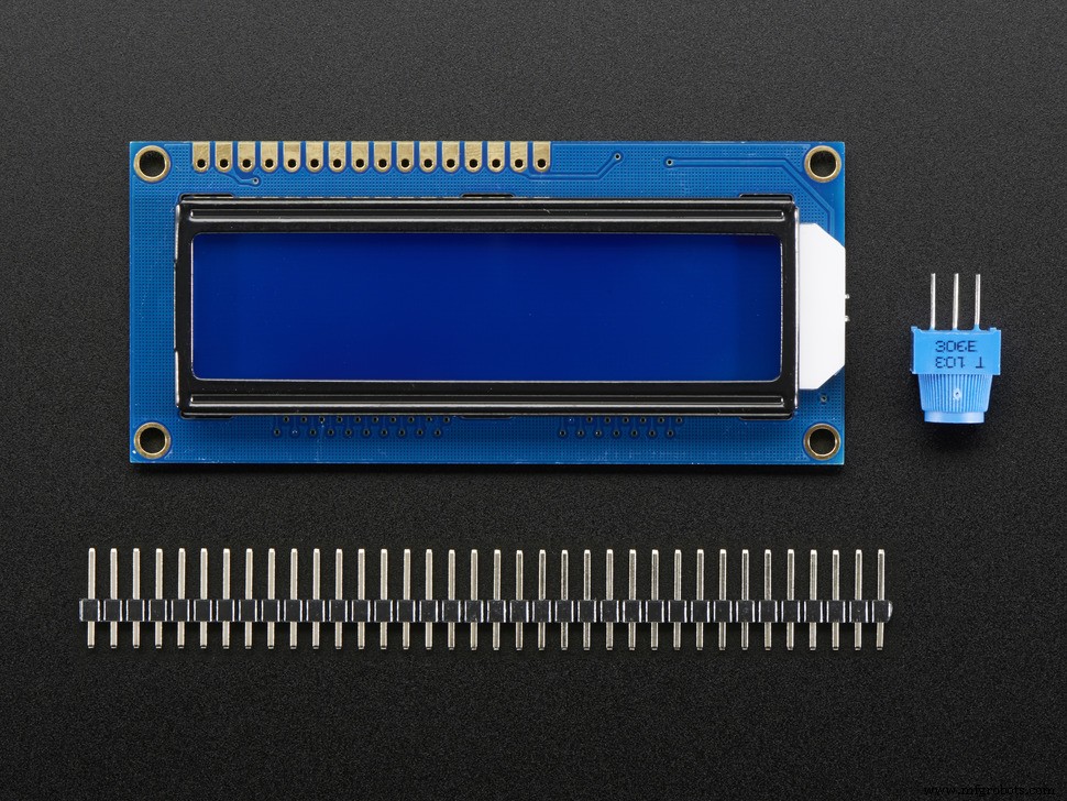
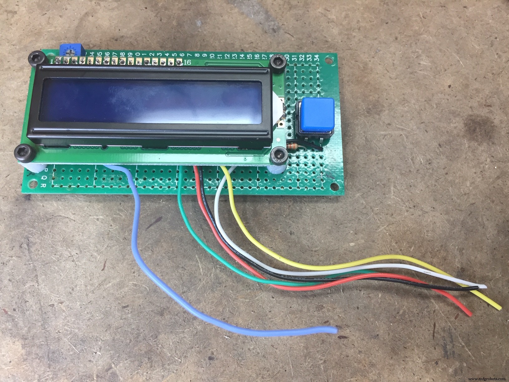
Before beginning assembly of front panel circuit board, insert LCD onto PY-5*10CM board (without soldering) with pin 1 of LCD in the C-1 hole location on board. Drill through perf board at the locations of the four LCD board mounting holes. Now remove remove LCD for later assembly.
Step 3
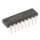
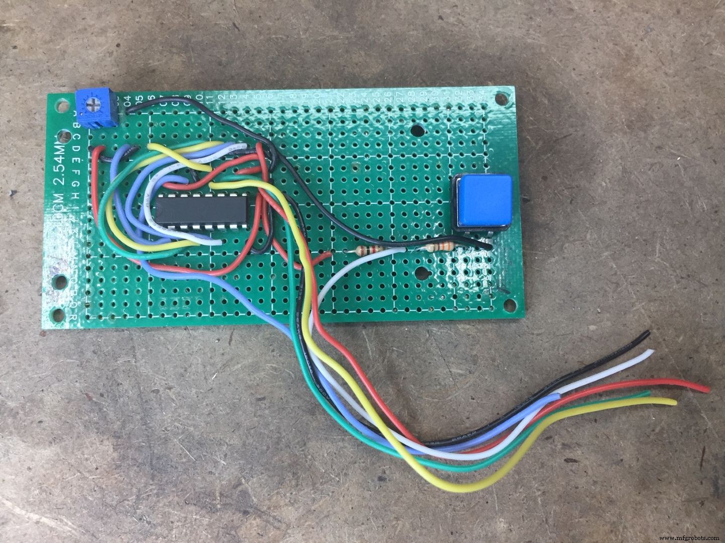
Assemble front panel circuit board. Place 74HC595N Shift Register IC, switches, and resistors as shown. Route all necessary wires (refer to wiring diagram) to location points that will be attached to the LCD Display, as well as 6" length that will extend to be later connected to the second board.
Step 4
Mount LCD onto the front panel board, using the printed spacers to raise LCD to clear the IC. Attach using 3mm x15mm cap screws and nuts. (All fasteners are available through Fastenal and/or McMaster Carr)
Step 5
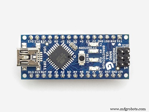
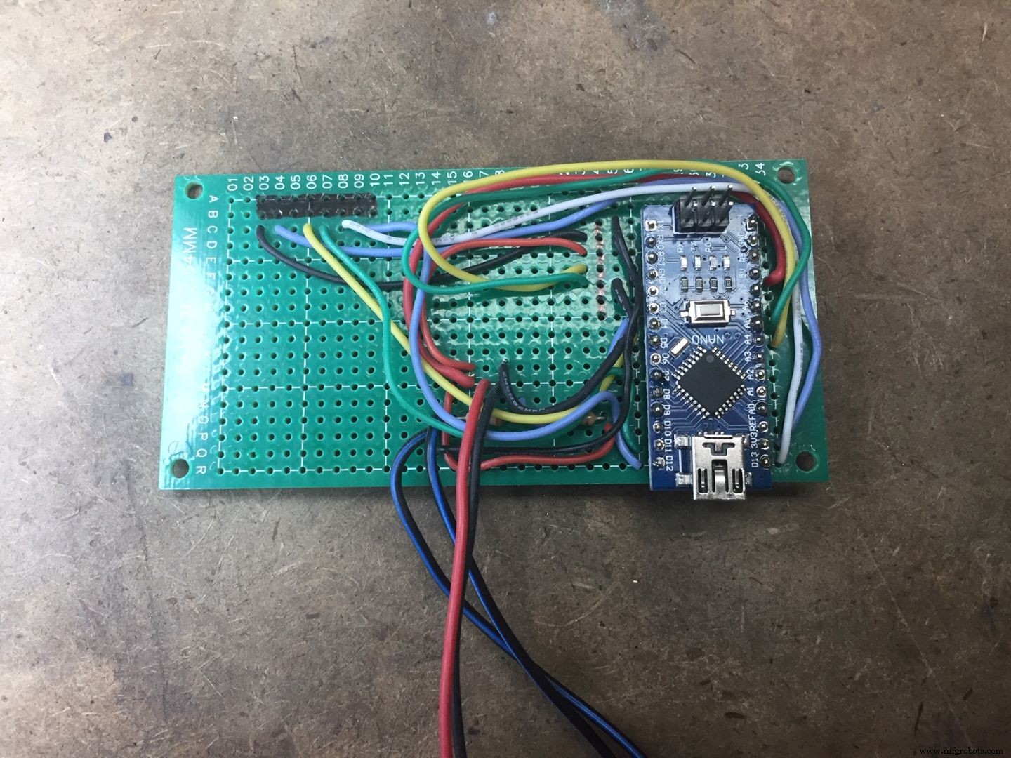
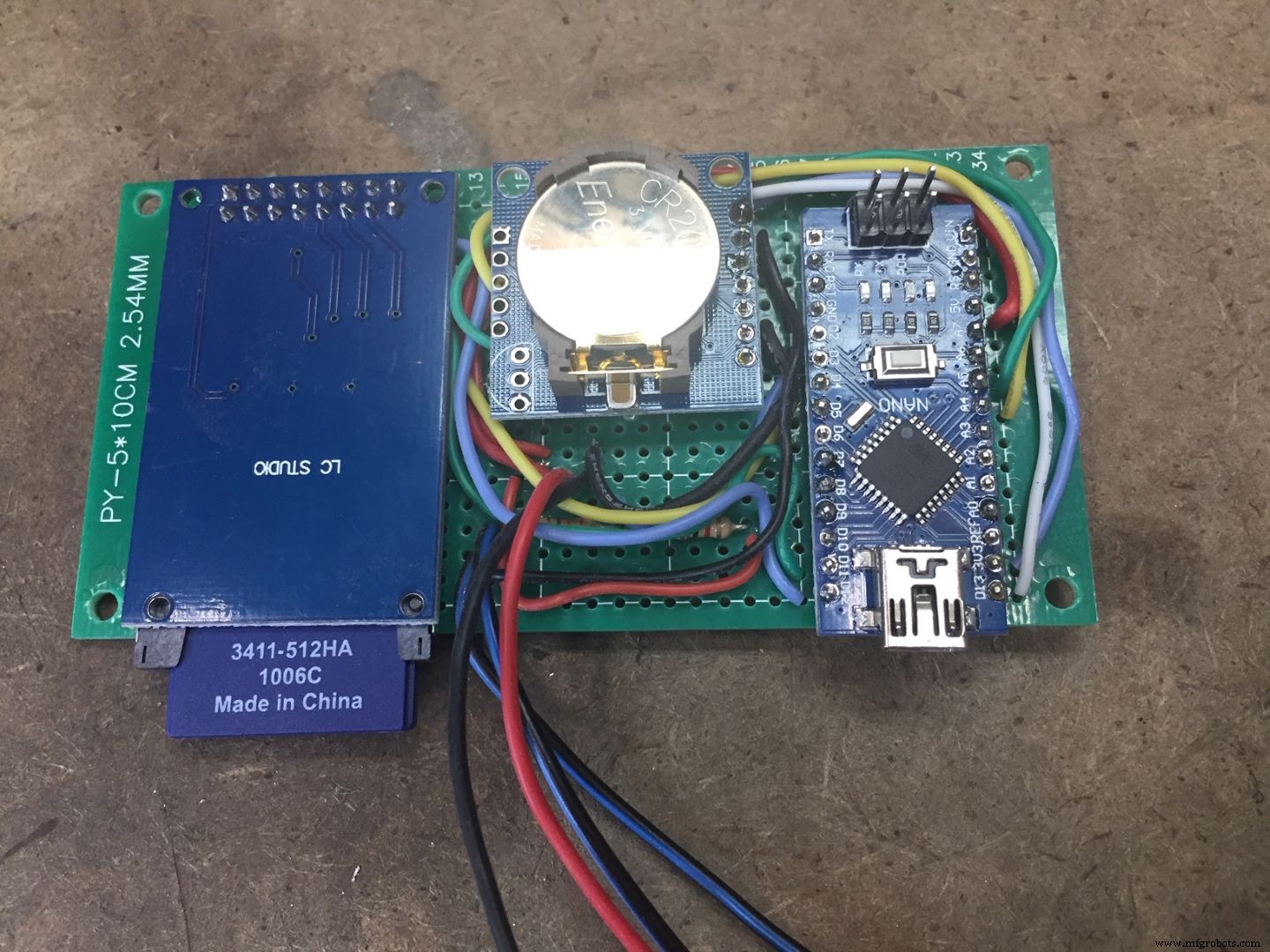
Assemble main circuit board by inserting Arduino with Pin D12 at the hole location R27 on circuit board. Add capacitor and resistors, and run all wiring to locations prior to inserting SD and RTC modules. Reference wiring schematic for all details.
Step 6
Assemble SD Reader at the hole locations A-3 through B-10. Assemble TinyRTC at hole locations C-24 through I-24. Solder all connections.
Step 7
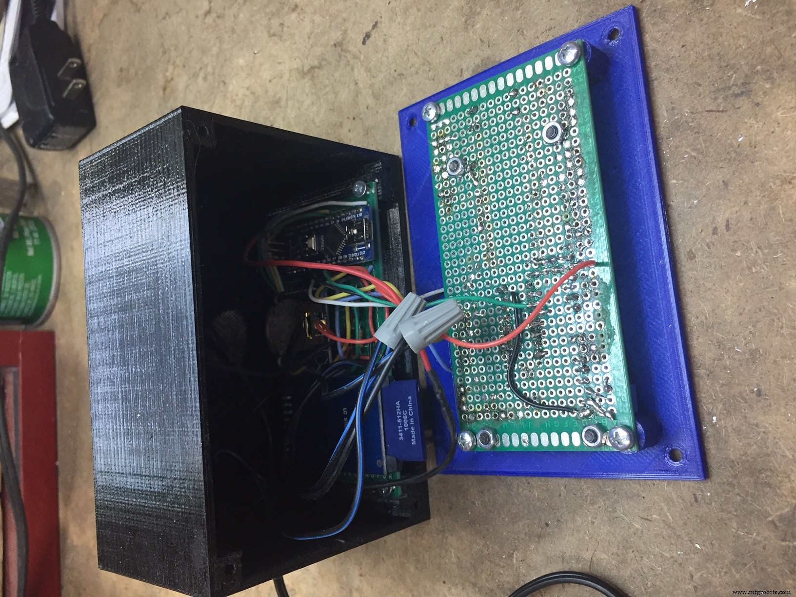
On the Indoor Unit Control Enclosure, drill holes at whatever location best meets your needs for the two wires that will go to outdoor unit, as well as holes for wires coming from external power supply or wall wart. Run wires through into enclosure, and solder at appropriate locations. Slide main board into case and attach with two 3mm x 6mm longs screws. Insert push button for switch through front cover and attache the front circuit board to front panel with 3mm x 6mm long screws. Note: I used a small turned brass piece for the switch button instead of the printed part, as I liked the 'feel' of it better.
Step 8
Attach the front cover using M3-0.5 x 10mm long Flathead screw
.
Step 9
Plugin USB to PC and upload the RTC program to set time. After clock is set, upload main program. Insert SD card. Test unit by shorting out the leads that go to reed switch on outdoor unit. Rainfall totals should increment for each short circuit (contact closed) event.Verify SD card is reading date by reading with a text editor such as Notepad or WordPad on a computer. There should be a file called"Text.txt". File will have a date stamp for each 'tip'event.
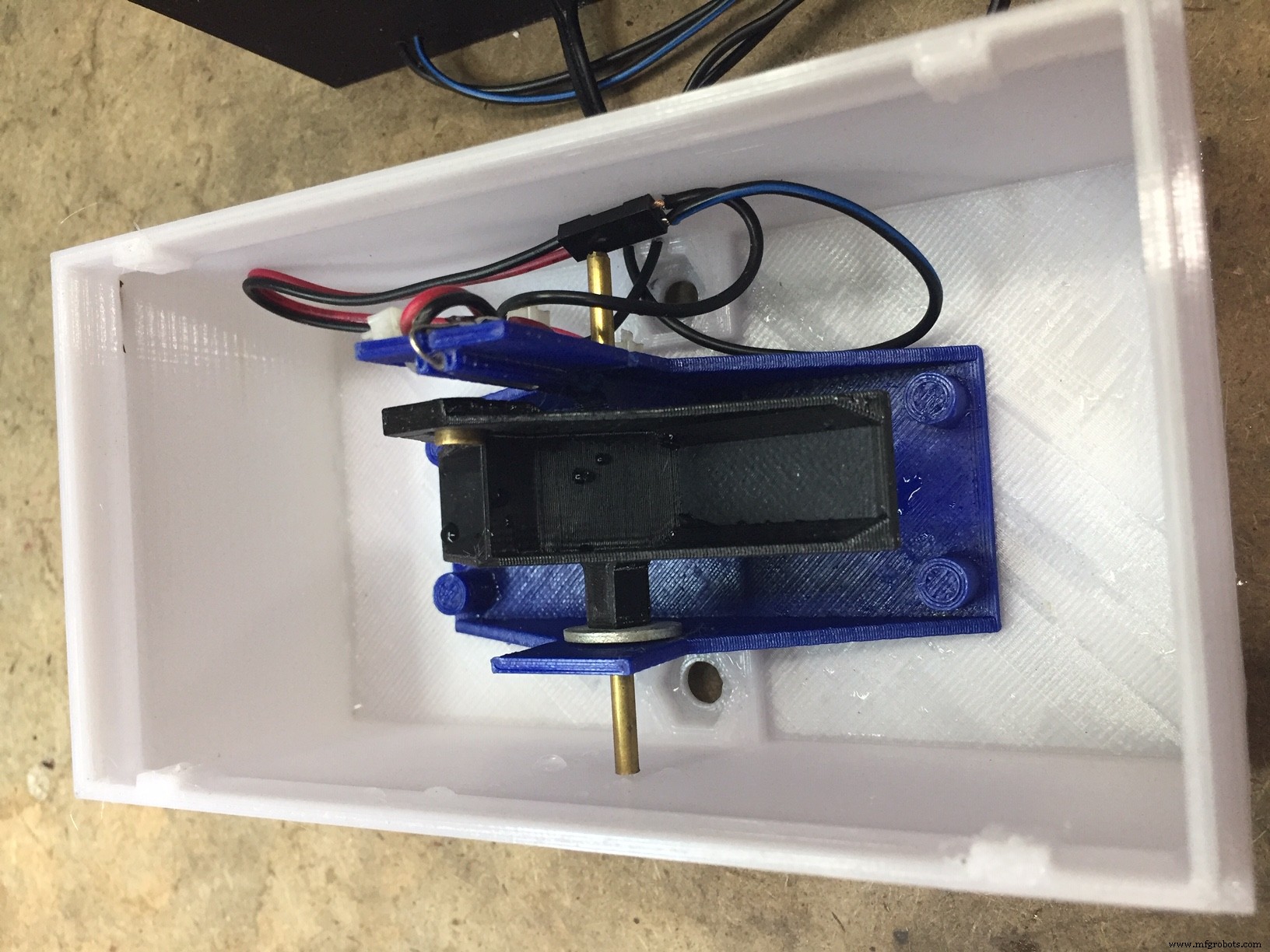
Step 10
Attach reed switch to the Sub Base. Use wire ties to hold in place. Assemble a magnet to the buck, and mount the bucket with a short piece of 1/8"diameter brass tubing (about 2" long). Note before assembling,run a 1/8" drill through the holes in bucket to clean up. Bucket needs to tip easily with no friction. Use a small round file in bucket holes if needed. Add a small 1/8" washer on the outermost side of bucket to close up spacing slightly. Determine how you will mount the outdoor unit. I used 1" aluminum angle. Attach the base to the angle or bracket using 1/4-20 hex bolts installed from inside out. Attach sub base to Outside unit bottom using M3-0.5x 10mm screws.
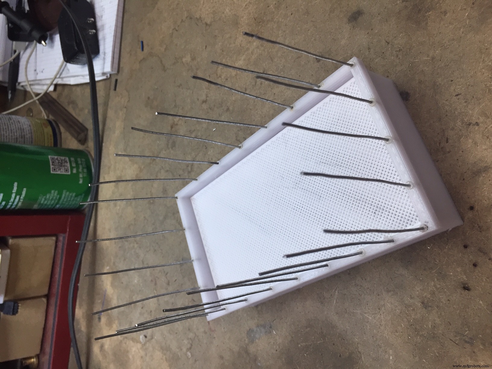
Step 11
Insert funnel into top enclosure. Cut approx. 24 pieces of 2" length 18 gauge galvanized wire. Holding a piece of wire with pliers, heat with a torch or lighter and carefully press into plastic top. These wires will deter birds from perching on the unit. You want to measure amount of rain not bird poop. Attach top to main enclosure with (4)M3-0.5x 6mm screws. Install the filter into funnel top. This filter will keep out leaves and prevent clogging.. Remember to check occasionally and clean as needed.
Step 12
Mount Outdoor unit and run wires to indoor unit. Make sure outdoor unit top is level in both directions.
Step 13
Power up unit and add water to outdoor unit to verify operation.
Step 14 (Optional)
To verify accuracy, you can very SLOWLY add one cup of water and check to see that the unit measure 0.87" of rainfall. (One cup = 14,44 cubic inches. Area of collector is 16.605" [Rainfall=14.44 cu.in./16.605"=0.87"]. You can adjust correction factor in main program if your unit differs from mine.
Congratulations!! Enjoy being able to track your rainfall.
Code
- Arduino Code to set time on RTC
- Main Program Arduino code For Rain Gauge
Arduino Code to set time on RTCArduino
Load this code first to set time on RTC. Edit the code with actual date and time before uploading to Arduino.#include "Wire.h"
#define DS1307_I2C_ADDRESS 0x68 // the I2C address of Tiny RTC
byte second, minute, hour, dayOfWeek, dayOfMonth, month, year;
// Convert normal decimal numbers to binary coded decimal
byte decToBcd(byte val)
{
return ( (val/10*16) + (val%10) );
}
// Convert binary coded decimal to normal decimal numbers
byte bcdToDec(byte val)
{
return ( (val/16*10) + (val%16) );
}
// Function to set the currnt time, change the second&minute&hour to the right time
void setDateDs1307()
{
second =00;
minute = 11;
hour = 12;
dayOfWeek = 5;
dayOfMonth =24;
month =7;
year= 20;
Wire.beginTransmission(DS1307_I2C_ADDRESS);
Wire.write(decToBcd(0));
Wire.write(decToBcd(second)); // 0 to bit 7 starts the clock
Wire.write(decToBcd(minute));
Wire.write(decToBcd(hour)); // If you want 12 hour am/pm you need to set
// bit 6 (also need to change readDateDs1307)
Wire.write(decToBcd(dayOfWeek));
Wire.write(decToBcd(dayOfMonth));
Wire.write(decToBcd(month));
Wire.write(decToBcd(year));
Wire.endTransmission();
}
// Function to gets the date and time from the ds1307 and prints result
void getDateDs1307()
{
// Reset the register pointer
Wire.beginTransmission(DS1307_I2C_ADDRESS);
Wire.write(decToBcd(0));
Wire.endTransmission();
Wire.requestFrom(DS1307_I2C_ADDRESS, 7);
second = bcdToDec(Wire.read() & 0x7f);
minute = bcdToDec(Wire.read());
hour = bcdToDec(Wire.read() & 0x3f); // Need to change this if 12 hour am/pm
dayOfWeek = bcdToDec(Wire.read());
dayOfMonth = bcdToDec(Wire.read());
month = bcdToDec(Wire.read());
year = bcdToDec(Wire.read());
Serial.print(hour, DEC);
Serial.print(":");
Serial.print(minute, DEC);
Serial.print(":");
Serial.print(second, DEC);
Serial.print(" ");
Serial.print(month, DEC);
Serial.print("/");
Serial.print(dayOfMonth, DEC);
Serial.print("/");
Serial.print(year,DEC);
Serial.print(" ");
Serial.println();
//Serial.print("Day of week:");
}
void setup() {
Wire.begin();
Serial.begin(19200);
setDateDs1307(); //Set current time;
}
void loop()
{
delay(2000);
getDateDs1307();//get the time data from tiny RTC
}
Main Program Arduino code For Rain GaugeArduino
Main Program for Rain Gauge. Make sure you install all associated libraries before compiling your program. Reference website [ https://roboindia.com/tutorials/arduino-3-pin-serial-lcd/ ] for instructions on updating the LiquidCrystal library./*
Tipping Bucket Rain Gauge
Written by Bob Torrence
*/
#include <SPI.h>
#include <SD.h>
#include <Wire.h>
#include "RTClib.h"
#include <LiquidCrystal_SR.h> // includes the LiquidCrystal Library (special version) ref https://roboindia.com/tutorials/arduino-3-pin-serial-lcd/
// Defining LCD and Pins for interfacing.
LiquidCrystal_SR lcd(6, 5, 9); // Pin 6 - Data Enable/ SER, Pin 5 - Clock/SCL, Pin 9 -SCK
RTC_DS3231 rtc;
int backlight = 7; // the pin the LED is connected to pin 7 (D7)
// constants won't change. They're used here to set pin numbers:
const byte interruptPin_bucket = 3;
const byte interruptPin_menu = 2;
// Variables will change:
volatile int Bucket_Tip_Occurence;
volatile int Menu_Select;
float Bucket_tip_hour_total = 0;
float Bucket_tip_current_hour_total = 0;
float Bucket_tip_previous_hour_total = 0;
float Bucket_tip_current_day_total = 0;
float Bucket_tip_previous_day_total = 0;
int current_minute;
int loop_minute;
int current_hour;
int loop_hour;
int current_day;
int loop_day;
int tip_counter;
float conversion_factor = .00854; //inches of rain per tip - calculated by measuring bucket volume and area of collector (16.605 sq.in.)
volatile unsigned long backlightOfftime;
volatile unsigned long backlightOnDuration=30000; // duration (miiliseconds) that backlight remains on aftter menu select button pushed
String print_time(DateTime timestamp) {
char message[120];
int Year = timestamp.year();
int Month = timestamp.month();
int Day = timestamp.day();
int Hour = timestamp.hour();
int Minute = timestamp.minute();
int Second= timestamp.second();
sprintf(message, "%02d:%02d:%02d %02d/%02d", Hour,Minute,Second,Month,Day);
return message;
}
File myFile;
void setup() {
lcd.begin(16,2); // Initializes the interface to the LCD screen, and specifies the dimensions (width and height) of the display
lcd.home(); // Setting Cursor at Home i.e. 0,0
rtc.begin(); //initiate use of Real Time Clock variables
pinMode(10, OUTPUT);
pinMode(backlight, OUTPUT); // Declare the LED as an output
digitalWrite(backlight,HIGH); //turn on lcd backlight
backlightOfftime = millis() + backlightOnDuration; //set inital time delay for the LCD backlight to be On
if (!SD.begin(4)) {
lcd.print("insert SD Card");
return;
}
// Set up our digital pin as an interrupt for bucket
pinMode(interruptPin_bucket, INPUT_PULLUP);
attachInterrupt(digitalPinToInterrupt(interruptPin_bucket), count, FALLING);
// Set up our digital pin as an interrupt for bucket
pinMode(interruptPin_menu, INPUT_PULLUP);
attachInterrupt(digitalPinToInterrupt(interruptPin_menu), menu, RISING);
myFile = SD.open("test.txt", FILE_WRITE);
if (myFile) {
myFile.println("Rain Gauge Ready - unit powered up");
myFile.close();
}
DateTime now = rtc.now() ;
current_minute = now.minute();
loop_minute = now.minute();
current_hour = now.hour();
loop_hour = now.hour();
lcd.setCursor (0,0);
lcd.print(print_time(now)); // Prints "Arduino" on the LCD
lcd.setCursor(1,1);
lcd.print("Rain Gauge");
}
void loop(){
DateTime now = rtc.now() ;
current_minute = now.minute();
loop_minute = now.minute();
current_hour = now.hour();
loop_hour = now.hour();
current_day = now.day();
loop_day = now.day();
//Begin Loop to determine tally current day totals
while (loop_day - current_day == 0){
//Begin Loop to determine tally current hour totals
while (loop_hour - current_hour == 0){
if (millis() > backlightOfftime) {
digitalWrite(backlight,LOW);
}
if (Bucket_Tip_Occurence == 1) {
Bucket_Tip_Occurence = 0;
tip_counter = tip_counter + 1;
DateTime now = rtc.now() ;
myFile = SD.open("test.txt", FILE_WRITE);
myFile.print("Event ");
myFile.print(now.year(), DEC);
myFile.print('/');
myFile.print(now.month(), DEC);
myFile.print('/');
myFile.print(now.day(), DEC);
myFile.print(" ");
myFile.print(now.hour(), DEC);
myFile.print(':');
myFile.print(now.minute(), DEC);
myFile.print(':');
myFile.print(now.second(), DEC);
myFile.print(" ");
myFile.print(conversion_factor,5);
myFile.println();
myFile.close();
delay(200); }
else { //Check for current hour status
DateTime now = rtc.now() ;
loop_hour= now.hour();}
switch (Menu_Select) {
case 1:
lcd.clear();
lcd.setCursor(0,0);
lcd.print("Current Hour");
lcd.setCursor(0,1);
lcd.print(tip_counter * conversion_factor);
delay(500);
break;
case 2:
lcd.clear();
lcd.setCursor(0,0);
lcd.print("Previous Hour");
lcd.setCursor(0,1);
lcd.print(Bucket_tip_previous_hour_total);
delay(500);
break;
case 3:
lcd.clear();
lcd.setCursor(0,0);
lcd.print("Current Day");
lcd.setCursor(0,1);
lcd.print(Bucket_tip_current_day_total + tip_counter * conversion_factor);
delay(500);
break;
case 4:
lcd.clear();
lcd.setCursor(0,0);
lcd.print("Previous Day");
lcd.setCursor(0,1);
lcd.print(Bucket_tip_previous_day_total);
// lcd.print(print_time(now));
delay(500);
break;
}
}
DateTime now = rtc.now() ;
// Reset counters for next one hour loop
current_hour = now.hour();
loop_day = now.day();
loop_hour= now.hour();
//Totalize current hour total
Bucket_tip_previous_hour_total = tip_counter * conversion_factor;
Bucket_tip_current_day_total = Bucket_tip_previous_hour_total + Bucket_tip_current_day_total;
tip_counter = 0;
/* Optional file write with only hourly total
myFile = SD.open("test.txt", FILE_WRITE);
myFile.print("Hourly Summary ");
myFile.print(Bucket_tip_previous_hour_total);
myFile.print(now.year(), DEC);
myFile.print('/');
myFile.print(now.month(), DEC);
myFile.print('/');
myFile.print(now.day(), DEC);
myFile.print(" ");
myFile.print(now.hour(), DEC);
myFile.print(':');
myFile.print(now.minute(), DEC);
myFile.print(':');
myFile.print(now.second(), DEC);
myFile.print(" ");
myFile.print(Bucket_tip_previous_hour_total);
myFile.println();
myFile.close();
delay(200);
*/
}
//Totalize current hour total
Bucket_tip_previous_day_total = Bucket_tip_current_day_total;
Bucket_tip_current_day_total = 0;
Bucket_tip_current_hour_total = 0;
tip_counter = 0;
/* Optional file write with previous day total only
myFile = SD.open("test.txt", FILE_WRITE);
myFile.print("Day Total ");
myFile.print(Bucket_tip_previous_day_total);
myFile.print(print_time(now));
myFile.close();
*/
}
//initaiate interrupt fromm bucket reed switch
void count() {
static unsigned long last_interrupt_time_bucket = 0;
unsigned long interrupt_time_bucket = millis();
// If interrupts come faster than 300ms, assume it's a bounce and ignore
if (interrupt_time_bucket - last_interrupt_time_bucket > 300)
{
Bucket_Tip_Occurence = 1;
}
last_interrupt_time_bucket = interrupt_time_bucket;
}
//initaiate interrupt fromm menu toggle switch
void menu() {
static unsigned long last_interrupt_time_menu = 0;
unsigned long interrupt_time_menu = millis();
// If interrupts come faster than 300ms, assume it's a bounce and ignore
if (interrupt_time_menu - last_interrupt_time_menu > 300)
{
if (digitalRead(backlight)== LOW) {
digitalWrite(backlight,HIGH); //turns on backlight if was previously off
}
else
Menu_Select = Menu_Select + 1;
if(Menu_Select > 4){
Menu_Select = 1;
}
backlightOfftime = millis() + backlightOnDuration;
Menu_Select = Menu_Select;
last_interrupt_time_menu = interrupt_time_menu;
}}
Custom parts and enclosures
STL for 3D Printing Outdoor unit base. I printed with PETG at 30% infillSTL file for 3D printing outdoor unit cover. I printed with PETG at 30% infillSTL File for 3D Printing outdoor unit funnel. I printed using PETG at 30% infill.STL File for 3D Printing outdoor unit filter. I printed using PETG at 20% infill. This part must be printed with NO horizontal bottom or top layers, creating a 'porous' filter.STL file for 3D Printing the sub base that the bucket attaches to through pivot rod. I printed using PETG with 30% infill.STL File for 3D Printing the bucket. I printed using PETG with 30% infill.STL File for printing the indoor unit enclosure. I printed with PETG at 30% infill.STL file for 3D Printing the front cover for indoor unit. I printed with PETG at 30% infill.STL file to print spacers to keep LCD unit raised above the shift register IC. I printed using PETG at 30% infill.Fusion 360 model of outdoor unitrain_gauge_assembly___smaller_profile_v15_CFg0dGwM8s.f3d.STP file of outdoor unitrain_gauge_assembly___smaller_profile_v15_jWCS0hjSDq.stepSTEP Cad model of indoor Unitcontroller_box_v1_fwltgu6D0S.stepFusion 36 CAD model of Outdoor unitcontroller_box_v1_NxtSrPG4Vo.f3zSTL file for 3D Printing the Switch push buttonSchematics
Project Wiring Schematicrain_gauge_NtjqXF6QEw.fzzManufacturing process
- Precision Pressure Gauges for Industrial & Safety Applications
- Smart Blinds: Automated Light Control with Arduino & Solar Power
- Build an AI LCD Companion: Your Interactive Buddy
- Touch‑Free Gesture Lock: Secure Access with APDS‑9960 and Arduino
- Arduino Nano Companion Kit – Essential Components & Tools for DIY Electronics
- SmartPostBox: IoT-Enabled Intelligent Mailbox System
- Ultrasonic Eyes: Interactive 8x8 LED Matrix Distance Sensor
- How Pressure Gauges Work: Types, Functions, and Benefits
- Mastering Strain Gauges: How They Convert Mechanical Stress into Precise Electrical Signals
- The Pirani Gauge Explained: Working Principles, Applications, and Benefits