


Wireless Laser Data Transmission (LiFi) – 100 b/s Performance Overview
Components and supplies
 |
| × | 2 | |||
 |
| × | 2 | |||
 |
| × | 2 | |||
 |
| × | 30 | |||
| × | 1 | ||||
 |
| × | 2 | |||
 |
| × | 2 | |||
 |
| × | 1 | |||
 |
| × | 1 | |||
 |
| × | 2 | |||
 |
| × | 3 |
Necessary tools and machines
 |
| |||
 |
|
Apps and online services
 |
|
About this project
This project is made of two parts the emitter and the receiver it can be used to send texts over laser using a keyPad and an LCD
Code
- LI-FI Transmitter Code V 2.0
- LI-FI Receiver Code V 2.0
LI-FI Transmitter Code V 2.0C/C++
LI-FI Transmitter Code V 2.0/*LI-FI Transmitter Code V 2.0
Written By HOUALEF AHMED RAMZI
Started on 29-9-2020
Last Update on 14-10-2020
*/
#define LaserPin 2
#include <LiquidCrystal.h>
const int rs = 12, en = 11, d4 = 6, d5 = 5, d6 = 4, d7 = 3;
LiquidCrystal lcd(rs, en, d4, d5, d6, d7);
int incomingchar;
int KeyPad_R[] = {A2, A1, 9, 7}; //The KeyPad rows
int KeyPad_C[] = {8, 10, A3}; // The KeyPad Columns
int KeyReturn = 0; // The Output of the Keypad Function from 1-12
int ABC; //variable used to code 3 chars using one button
int Row; //variable used in the Keypad function
int Column;//variable used in the Keypad function
int StCursor = 0; //variable for the Cursor Control
int NdCursor = 0; //variable for the Cursor Control
int outcomingmatrix[32][5]; //The DATA Buffer
int m = 0;// variable used to know the length of the outcomingmatrix to avoid sending all the 32*5 emty buffer
int A[] = {1, 1, 1, 1, 0}, B[] = {0, 0, 0, 1, 0}, C[] = {0, 0, 0, 1, 1}, D[] = {0, 0, 1, 0, 0}, E[] = {0, 0, 1, 0, 1}, F[] = {0, 0, 1, 1, 0}, G[] = {0, 0, 1, 1, 1}, H[] = {0, 1, 0, 0, 0};
int I[] = {0, 1, 0, 0, 1}, J[] = {0, 1, 0, 1, 0}, K[] = {0, 1, 0, 1, 1}, L[] = {0, 1, 1, 0, 0}, M[] = {0, 1, 1, 0, 1}, N[] = {0, 1, 1, 1, 0}, O[] = {0, 1, 1, 1, 1}, P[] = {1, 0, 0, 0, 0};
int Q[] = {1, 0, 0, 0, 1}, R[] = {1, 0, 0, 1, 0}, S[] = {1, 0, 0, 1, 1}, T[] = {1, 0, 1, 0, 0}, U[] = {1, 0, 1, 0, 1}, V[] = {1, 0, 1, 1, 0}, W[] = {1, 0, 1, 1, 1}, X[] = {1, 1, 0, 0, 0};
int Y[] = {1, 1, 0, 0, 1}, Z[] = {1, 1, 0, 1, 0}, SPACE[] = {1, 1, 1, 1, 1}; // a small data base to stor all coded charachters
void setup() {
lcd.begin(16, 2);
pinMode(LaserPin, OUTPUT);
Serial.begin(9600);
for (int i; i < 4; i++) {
pinMode( KeyPad_R[i], OUTPUT);
}
for (int j; j < 3; j++) {
pinMode( KeyPad_C[j], INPUT);
}
lcd.print("HOUALEF RAMZI");
delay(5000);
lcd.clear();
lcd.setCursor(0,0);
}
void conv(int alpha [5], char Char ) { // TO FILL THE OUTPUT BUFFER FROM THE DATA BASE
for (int i = 0; i < 5; i++) {
outcomingmatrix[m][i] = alpha[i];
}
lcd.print(Char);
}
void start_bit() { //THE START BIT
digitalWrite(LaserPin, HIGH);
delay(9);
digitalWrite(LaserPin, LOW);
}
void KeyPad() { // OUTPUTS THE BUTTON'S NUMBER PRESSED FROM 1 TO 12
for (int i = 0; i < 4; i++) {
digitalWrite( KeyPad_R[i], HIGH);
for (int j = 0; j < 3; j++) {
if (digitalRead(KeyPad_C[j]) == 1) {
Row = i;
Column = j;
digitalWrite( KeyPad_R[i], LOW);
if (Row == 0) {
switch (Column) {
case 0: KeyReturn = 1; break; case 1: KeyReturn = 2; break; case 2: KeyReturn = 3; break;
}
}
if (Row == 1) {
switch (Column) {
case 0: KeyReturn = 4; break; case 1: KeyReturn = 5; break; case 2: KeyReturn = 6; break;
}
}
if (Row == 2) {
switch (Column) {
case 0: KeyReturn = 7; break; case 1: KeyReturn = 8; break; case 2: KeyReturn = 9; break;
}
}
if (Row == 3) {
switch (Column) {
case 0: KeyReturn = 10; break; case 1: KeyReturn = 11; break; case 2: KeyReturn = 12; break;
}
}
}
}
} Serial.println(KeyReturn);
}
void KeyToAscii(int KeyN, int FirtAsciiValue) { // TO CONVERT DATA FROM THE KEYPAD TO THE ASCII VALUE TO WORK WITH THE CONV FUNCTION ABOVE THAT'S HOW WE CAN USE BOTH OF SERIAL MONITOR AND THE KEYPAD
if (KeyReturn == KeyN) {
incomingchar = FirtAsciiValue + ABC;
ABC++;
if (ABC == 3) {
ABC = 0;
}
}
}
void CursorControler() {
lcd.setCursor(StCursor, NdCursor);
if (KeyReturn == 10) { //TO CONFIRM THE CHARACTERS BECAUSE 11 IN THE CONFIRM BUTTON
delay(100);
StCursor++;
m++;
}
if (StCursor == 16) { // TO WRITE IN NEW LINE WHEN THE FIRST IS FULL
StCursor = 0;
NdCursor = 1;
}
}
void loop() {
KeyPad();
delay(150);
CursorControler();
KeyToAscii(1, 65); KeyToAscii(2, 68); KeyToAscii(3, 71); KeyToAscii(4, 74); KeyToAscii(5, 77); KeyToAscii(6, 80); KeyToAscii(7, 83); KeyToAscii(8, 86); KeyToAscii(9, 89); KeyToAscii(11, 32);
switch (incomingchar) {
case 65: conv(A, 'A'); break; case 66: conv(B, 'B'); break; case 67: conv(C, 'C'); break; case 68: conv(D, 'D'); break; case 69: conv(E, 'E'); break; case 70: conv(F, 'F'); break; case 71: conv(G, 'G'); break;
case 72: conv(H, 'H'); break; case 73: conv(I, 'I'); break; case 74: conv(J, 'J'); break; case 75: conv(K, 'K'); break; case 76: conv(L, 'L'); break; case 77: conv(M, 'M'); break; case 78: conv(N, 'N'); break;
case 79: conv(O, 'O'); break; case 80: conv(P, 'P'); break; case 81: conv(Q, 'Q'); break; case 82: conv(R, 'R'); break; case 83: conv(S, 'S'); break; case 84: conv(T, 'T'); break; case 85: conv(U, 'U'); break;
case 86: conv(V, 'V'); break; case 87: conv(W, 'W'); break; case 88: conv(X, 'X'); break; case 89: conv(Y, 'Y'); break; case 90: conv(Z, 'Z'); break; case 32: conv(SPACE, ' '); break; case 33: conv(SPACE, ' '); break;
}
//TO USE THE SPACE FROM THE SERIAL MONITOR YOU HAVE TO CHANGE CASE 91 TO CASE 32
if (KeyReturn == 12) { //TO SEND DATA BECAUSE 12 IS THE SEND BUTTON
delay(100);
for (int j = 0; j < m; j++) {
start_bit();
for (int i = 0; i < 5; i++) {
digitalWrite(LaserPin, outcomingmatrix[j][i]);
delay(10);
}
digitalWrite(LaserPin, LOW);
delay(20);
}
for (int k = 0; k < 32; k++) {
for (int l = 0; l < 5; l++) {
outcomingmatrix[k][l] = 0; // To Clear The buffer
}
}
}
incomingchar = 0; // To Avoid continuous DATA storing
KeyReturn = 0; // That means no button is pressed currently
}
LI-FI Receiver Code V 2.0C/C++
LI-FI Receiver Code V 2.0/*LI-FI Receiver Code V 2.0
Written By HOUALEF AHMED RAMZI
Started on 29-9-2020
Last Update on 14-10-2020
*/
#include <LiquidCrystal.h>
#define SolarCell A0 //To define the input pin of the solarcell
int StCursor = 0; // To control the lcd Cursor
int A[] = {1, 1, 1, 1, 0}, B[] = {0, 0, 0, 1, 0}, C[] = {0, 0, 0, 1, 1}, D[] = {0, 0, 1, 0, 0}, E[] = {0, 0, 1, 0, 1}, F[] = {0, 0, 1, 1, 0}, G[] = {0, 0, 1, 1, 1}, H[] = {0, 1, 0, 0, 0};
int I[] = {0, 1, 0, 0, 1}, J[] = {0, 1, 0, 1, 0}, K[] = {0, 1, 0, 1, 1}, L[] = {0, 1, 1, 0, 0}, M[] = {0, 1, 1, 0, 1}, N[] = {0, 1, 1, 1, 0}, O[] = {0, 1, 1, 1, 1}, P[] = {1, 0, 0, 0, 0};
int Q[] = {1, 0, 0, 0, 1}, R[] = {1, 0, 0, 1, 0}, S[] = {1, 0, 0, 1, 1}, T[] = {1, 0, 1, 0, 0}, U[] = {1, 0, 1, 0, 1}, V[] = {1, 0, 1, 1, 0}, W[] = {1, 0, 1, 1, 1}, X[] = {1, 1, 0, 0, 0};
int Y[] = {1, 1, 0, 0, 1}, Z[] = {1, 1, 0, 1, 0}, SPACE[] = {1, 1, 1, 1, 1};
const int rs = 12, en = 11, d4 = 5, d5 = 4, d6 = 3, d7 = 2;
int Cell_Input; // The input of the Solar-Cell
int Threshold;
int info[5]; //The received DATA
LiquidCrystal lcd(rs, en, d4, d5, d6, d7);
void setup() {
pinMode(A0, INPUT);
Serial.begin(9600);
lcd.begin(16, 2);
lcd.setCursor(0, 0);
Threshold = analogRead(SolarCell) + 10;
lcd.print("READY TO RECEIVE");
delay(5000);
lcd.clear();
}
void BufferClear() { // The clear the buffer
for (int i = 0; i < 5; i++) {
info[i] = 0;
}
}
void check_condition(int received_bits[5], int Binaryalpha[5], char Lcdalpha) {//To compare the received bits With the data base
if (received_bits[0] == Binaryalpha[0] && received_bits[1] == Binaryalpha[1] && received_bits[2] == Binaryalpha[2] && received_bits[3] == Binaryalpha[3] && received_bits[4] == Binaryalpha[4]) {
lcd.print(Lcdalpha);
CursorControler();
}
}
void CursorControler() { // To control the cursor
StCursor++;
if (StCursor == 16)
lcd.setCursor(0, 1);
}
void loop() {
Cell_Input = analogRead(SolarCell);
if (Cell_Input > Threshold) { // the start bit detection
delay(10); // timing
for (int i = 0; i < 5; i++) { // save data
if (analogRead(SolarCell) > Threshold) {
info[i] = 1;
}
else {
info[i] = 0;
}
delay(10);
}
check_condition(info, A, 'A'); check_condition(info, B, 'B'); check_condition(info, C, 'C'); check_condition(info, D, 'D');
check_condition(info, E, 'E'); check_condition(info, F, 'F'); check_condition(info, G, 'G'); check_condition(info, H, 'H');
check_condition(info, I, 'I'); check_condition(info, J, 'J'); check_condition(info, K, 'K'); check_condition(info, L, 'L');
check_condition(info, M, 'M'); check_condition(info, N, 'N'); check_condition(info, O, 'O'); check_condition(info, P, 'P');
check_condition(info, Q, 'Q'); check_condition(info, R, 'R'); check_condition(info, S, 'S'); check_condition(info, T, 'T');
check_condition(info, U, 'U'); check_condition(info, V, 'V'); check_condition(info, W, 'W'); check_condition(info, X, 'X');
check_condition(info, Y, 'Y'); check_condition(info, Z, 'Z'); check_condition(info, SPACE, ' ');
BufferClear();
}
}
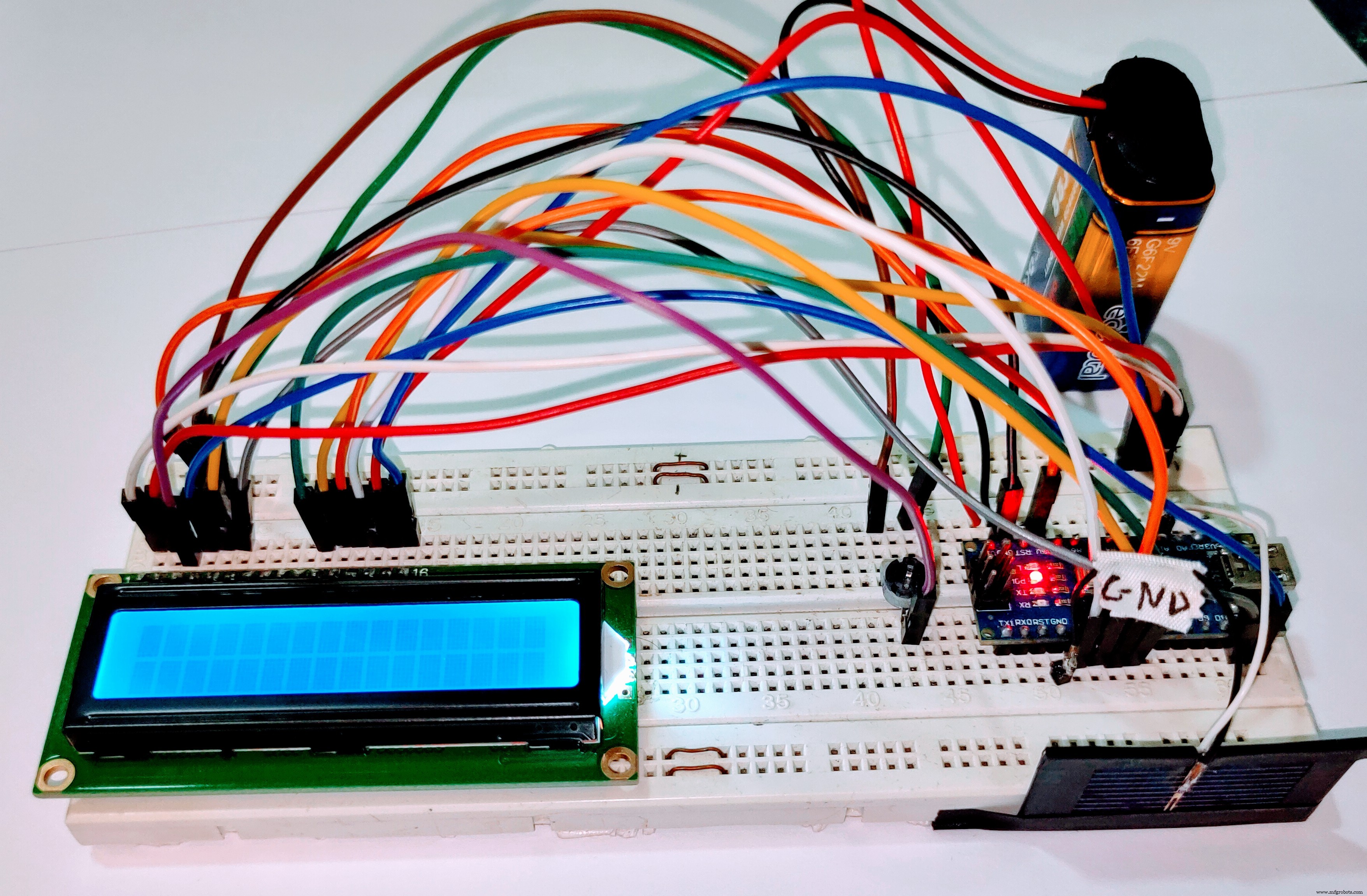
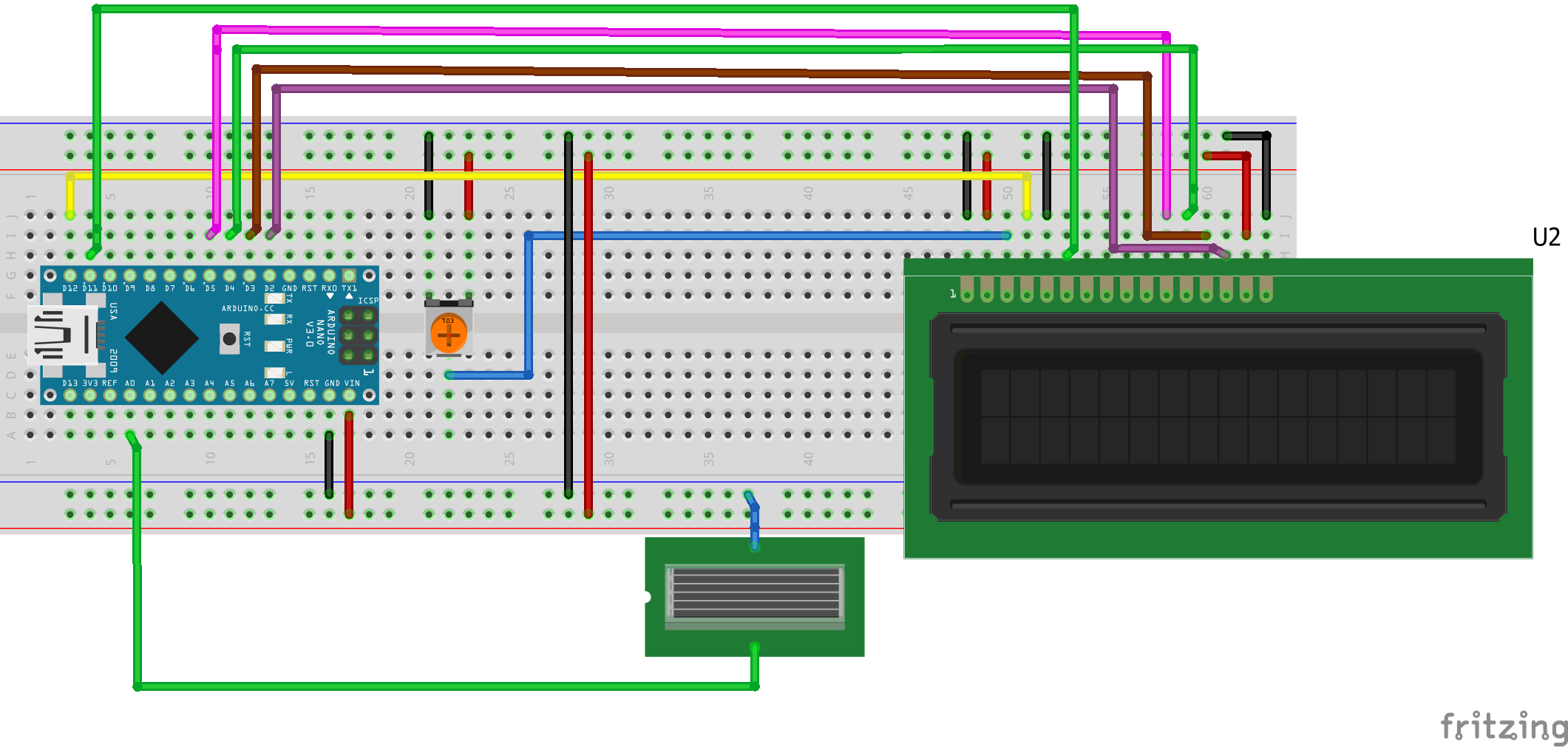
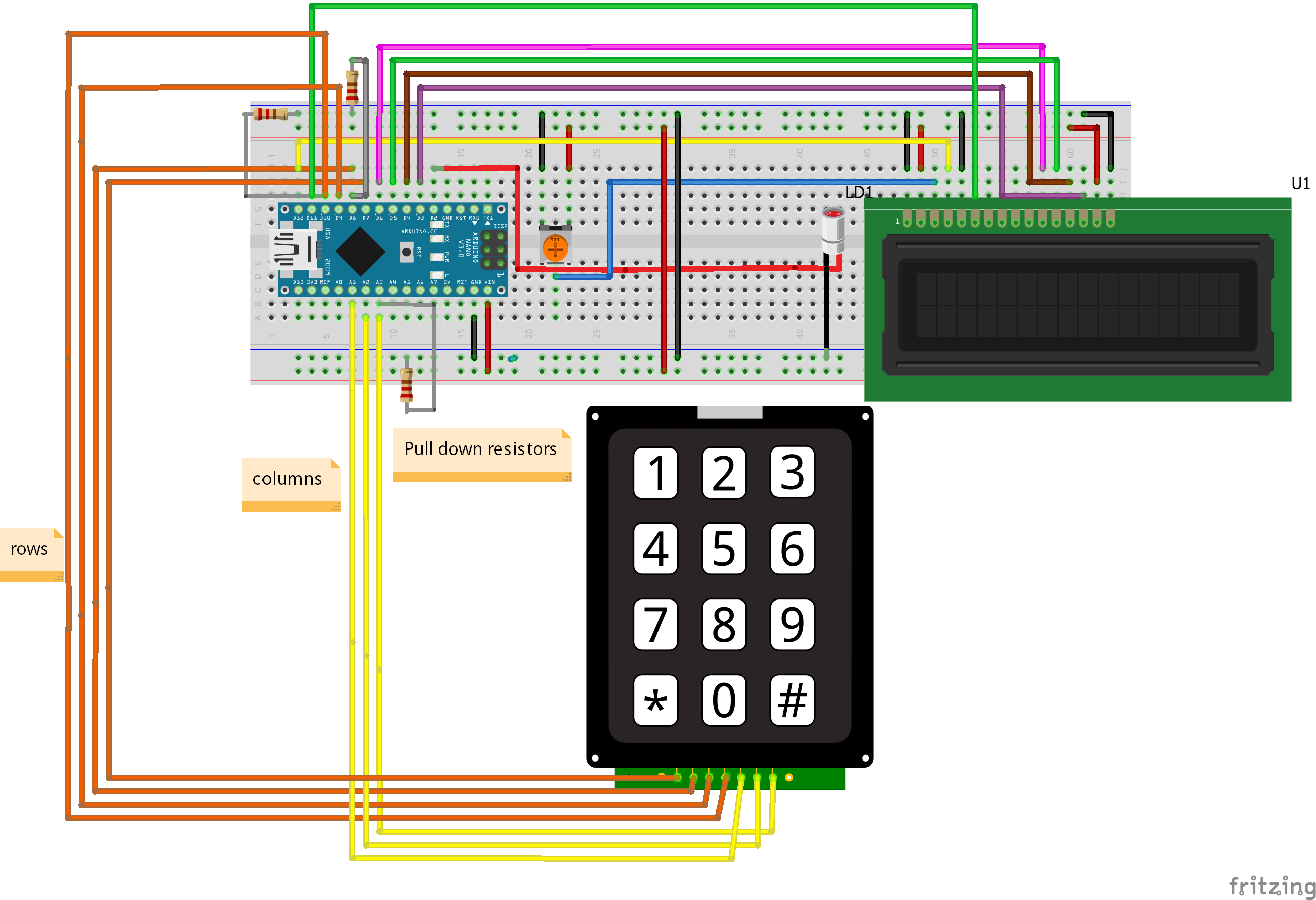
Schematics
the photo cell must be placed face to face with laser to receive dataLCD:
VSS ---> Ground
VDD ---> Arduino 5V
K ---> Ground
A ---> Arduino 5V
RW ---> Ground
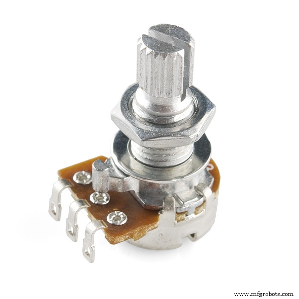
V0/VEE ---> The Vout of the potentiometer
RS ---> Arduino digital pin 12
EN ---> Arduino digital pin 11
D4 ---> Arduino digital pin 5
D5 ---> Arduino digital pin 4
D6 ---> Arduino digital pin 3
D7 ---> Arduino digital pin 2
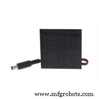
Solar Cell:
The Negative lead of the SC is connected to the ground
The Positive lead of the SC is connected to the Arduino Analog pin A0
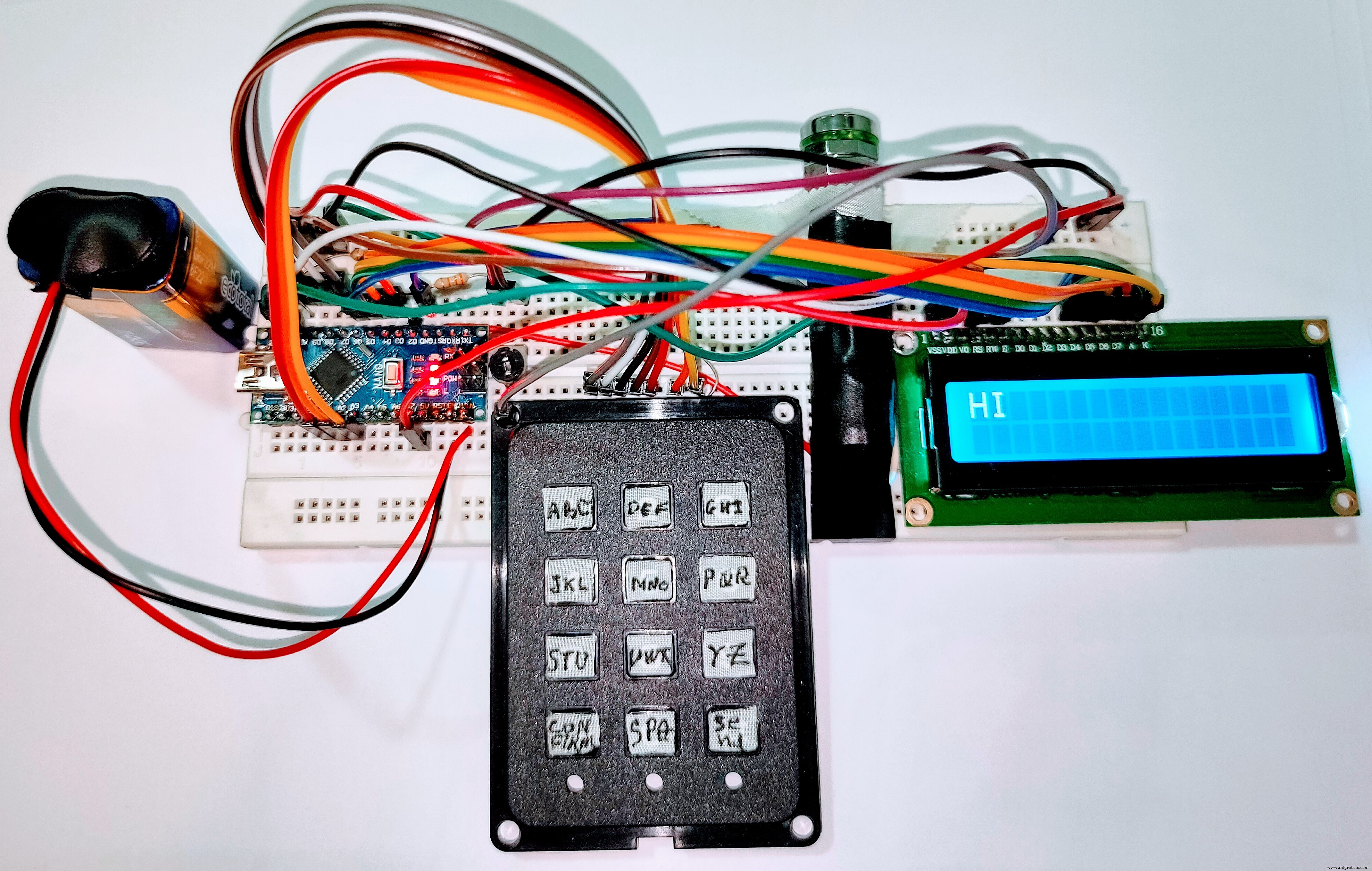
 the user must choose what he wants to send using the keypad and the LCD ,after typing each letter you should press the confirm button and eventually press the send button .
LCD:
VSS ---> Ground
VDD ---> Arduino 5V
K ---> Ground
A ---> Arduino 5V
RW ---> Ground
V0/VEE ---> The Vout of the potentiometer
RS ---> Arduino digital pin 12
EN ---> Arduino digital pin 11
D4 ---> Arduino digital pin 6
D5 ---> Arduino digital pin 5
D6 ---> Arduino digital pin 4
D7 ---> Arduino digital pin 3
KEYPAD:
A ---> Arduino Analog pin A2 //all analog pins are used as digital pins
B ---> Arduino Analog pin A1
C ---> Arduino digital pin 9
D ---> Arduino digital pin 7
1 ---> Arduino digital pin 8
2---> Arduino digital pin 10
3---> Arduino Analog pin A3
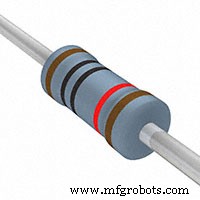
PULL-DOWN RESISTORS:
the first end of the resistor in connected to the Digital pin 8 and the 2nd to the ground
the first end of the resistor in connected to the Digital pin 10 and the 2nd to the ground
the first end of the resistor in connected to the Analog pin A3 and the 2nd to the ground
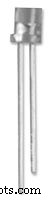
LASER DIODE:
The Cathode of the LD is connected to the ground
The Anode of the LD is connected to the Arduino digital pin 2
Arduino Handwashing Timer: Simple DIY Tool to Fight COVID‑19
Build a Precise 7‑Segment Clock with Arduino Pro Mini & DS1302 RTC
Manufacturing process
- Comprehensive Guide to Laser Marking: Types, Benefits, and Applications
- Laser Pointer: Design, Manufacturing, and Safety Overview
- Semiconductor Lasers: Precision Light Generation for Modern Technology
- Laser‑Guided Missiles: Development, Manufacturing, and Strategic Impact
- Revolutionary Electro-Optic Laser Delivers 30 GHz Pulse Rate for Ultra-Fast Imaging and Communications
- 3D RGB Arduclock – Bluetooth LED Timepiece with Real‑Time Clock
- Arduino Temperature & Humidity Logger Using DHT11 and Ethernet Shield
- River Health Monitor: Arduino-Based Water Quality System
- Interactive Joystick Game with Arduino and LED Feedback
- Build a Real-Time 360° Radar with Arduino – Step‑by‑Step Guide