


Advanced Arduino Collision Warning System – Visual & Audio Alerts for Vehicle Safety
Components and supplies
 |
| × | 1 | |||
| × | 1 | ||||
 |
| × | 2 | |||
 |
| × | 1 | |||
 |
| × | 2 |
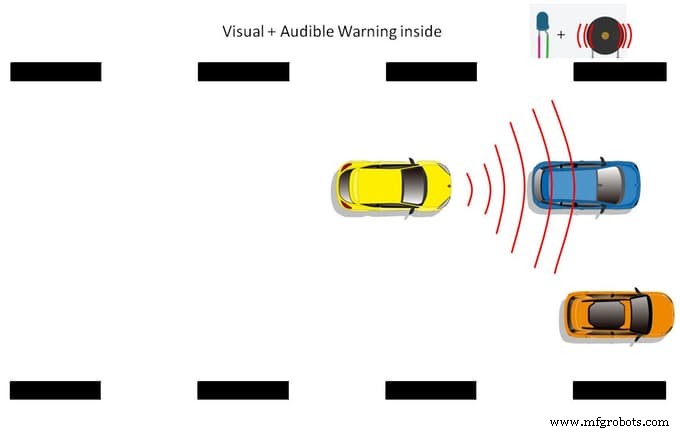
About this project
This is an Arduino-based collision detection warning system. This kind of system is the fastest growing safety feature in automotive industries. Such a system enables vehicles to identify the chances of collision and give visual and audio warning to driver, so that the driver can take necessary action to avoid collision. This project idea is based on an Arduino controller and the whole project will give you very good understanding of how this system works. The step-by-step method is explained so that you can make this system. The hardware connection, pin information and Arduino program is explained clearly.
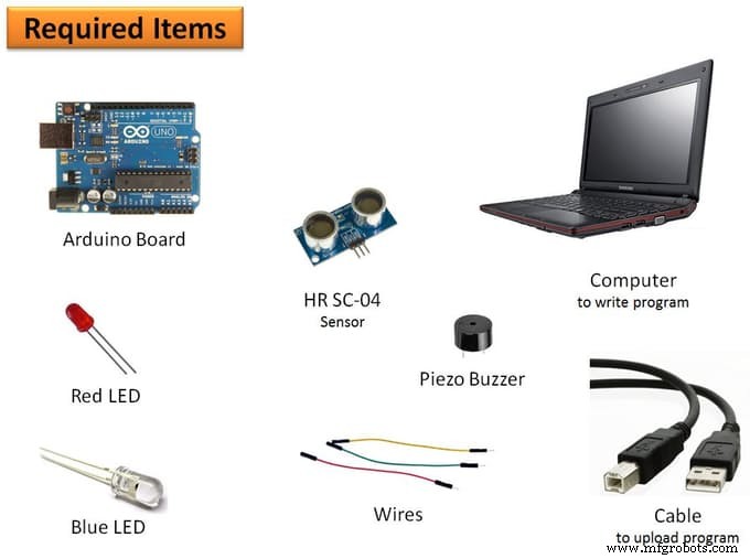
Step 1: Please gather the following items- Computer: This is required to write program and flash program to the controller. Also, you need to install Arduino IDE which is available free on the Arduino website download section.
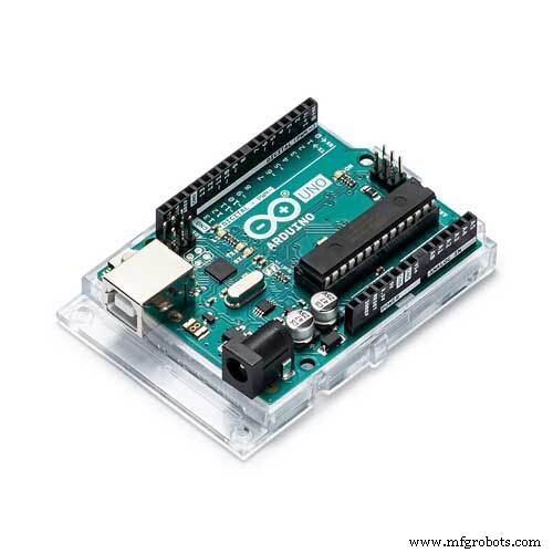
- Controller: I used Arduino micro-controller. This you can get from an online seller like Amazon, etc.
- Sensor: I used HR SC-04 ultrasonic sensor.
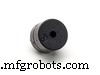
- Piezo Buzzer: I used Piezo buzzer to make the audio warning.
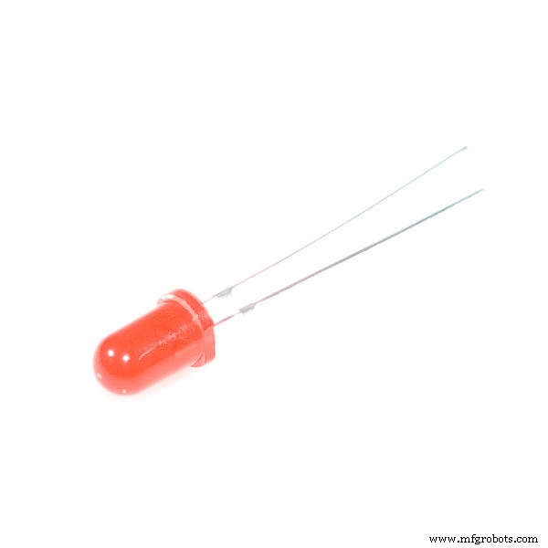
- LED: There are two colors of LED I used - red and blue.
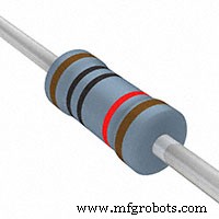
- Wires: Jumper wires are required to make hardware connections. You need to use all types of jumper wires like male-male, female-female and female-male.
The hardware you gather in first step, now connect all of them to the controller through wires.
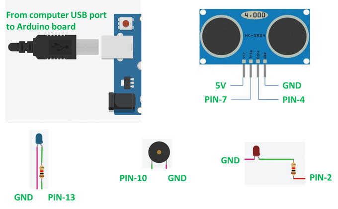
Sensor to controller pin information
The sensor has four pins: VCC, Trig, Echo, and GND. Connect:
- VCC pin to 5V on controller
- GND pin to GND on controller
- Trig pin to pin-7 on controller
- Echo pin to pin-4 on controller
Piezo Buzzer to controller pin information
Piezo buzzer has two pins:
- Connect one pin to pin-10 on controller
- Connect another pin to GND on controller
Red LED to controller pin information
The red LED has two pins:
- Connect one pin to pin-2 on controller
- Connect another pin to GND on controller
Blue LED to controller pin information
The blue LED has two pins:
- Connect one pin to pin-13 on controller
- Connect another pin to GND on controller
Controller to Computer connection information
You have a USB data cable that you get with buying the Arduino. With this data cable, you connect the computer to the Arduino board. Now launch Arduino IDE. After connecting the computer, you must select the board and port from the menu. Please see the attached screen shot for the help.

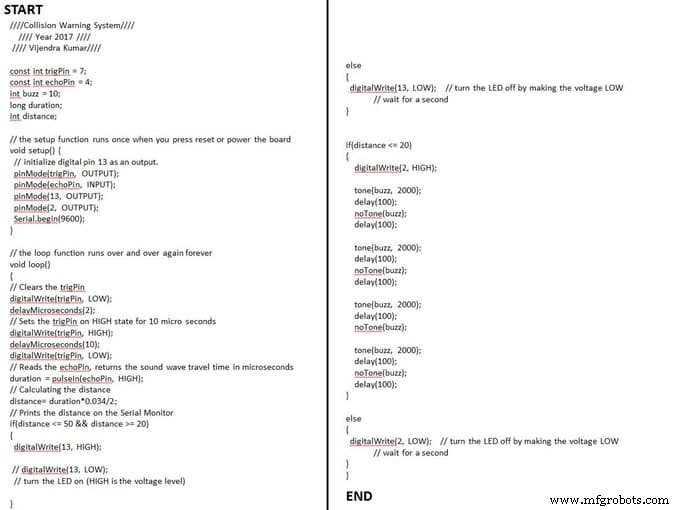
In the previous step, we defined pin information for the hardware. Now, that info we'll use to write program instructions. Launch Arduino IDE and try to write the program by yourself. Otherwise you can directly use my program or download the .ino format file attached.
While copying this code, you have to be careful because some characters used in the program cannot be paste while writing this on particular medium. Better to download .ino format file.
////Collision Warning System////
//// Year 2017 ////
//// Vijendra Kumar////
const int trigPin = 7;
const int echoPin = 4;
int buzz = 10;
long duration;
int distance;
// the setup function runs once when you press reset or power the board
void setup() {
// initialize digital pin 13 as an output.
pinMode(trigPin, OUTPUT);
pinMode(echoPin, INPUT);
pinMode(13, OUTPUT);
pinMode(2, OUTPUT);
Serial.begin(9600);
}
// the loop function runs over and over again forever
void loop()
{
// Clears the trigPin
digitalWrite(trigPin, LOW);
delayMicroseconds(2);
// Sets the trigPin on HIGH state for 10 micro seconds
digitalWrite(trigPin, HIGH);
delayMicroseconds(10);
digitalWrite(trigPin, LOW);
// Reads the echoPin, returns the sound wave travel time in microseconds
duration = pulseIn(echoPin, HIGH);
// Calculating the distance
distance= duration*0.034/2;
// Prints the distance on the Serial Monitor
if(distance <= 50 && distance >= 20)
{
digitalWrite(13, HIGH);
// digitalWrite(13, LOW);
// turn the LED on (HIGH is the voltage level)
}
else
{
digitalWrite(13, LOW); // turn the LED off by making the voltage LOW
// wait for a second
}
if(distance <= 20)
{
digitalWrite(2, HIGH);
tone(buzz, 2000);
delay(100);
noTone(buzz);
delay(100);
tone(buzz, 2000);
delay(100);
noTone(buzz);
delay(100);
tone(buzz, 2000);
delay(100);
noTone(buzz);
tone(buzz, 2000);
delay(100);
noTone(buzz);
delay(100);
}
else
{
digitalWrite(2, LOW); // turn the LED off by making the voltage LOW
// wait for a second
}
}
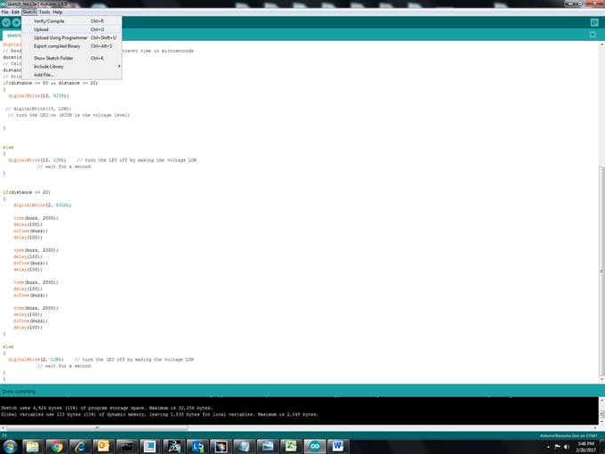
After making all the connections, we are ready to upload the program to the Arduino board. Please see the attached image for reference.
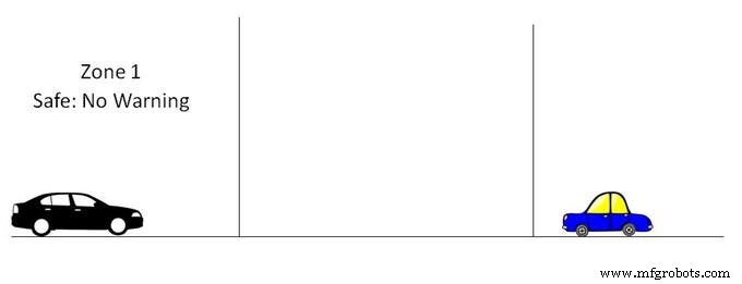
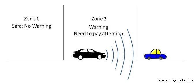
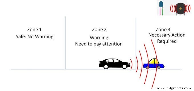
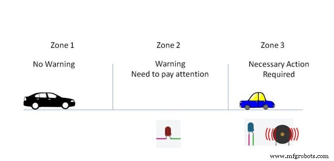
Let me explain for you how this system works. I defined three different zones:
- Zone 1: No warning
- Zone 2: Only visual warning (in this zone, driver has to pay attention)
- Zone 3: Both visual and audio warning (driver has to take necessary action to avoid collision)
Now the whole system is ready to test. Please see the above video to see the how to check that the system is working.
Code
- Arduino based collision detection warning system
Arduino based collision detection warning system Arduino
You can use this code for this system////Collision Warning System////
//// Year 2017 ////
//// Vijendra Kumar////
const int trigPin = 7;
const int echoPin = 4;
int buzz = 10;
long duration;
int distance;
// the setup function runs once when you press reset or power the board
void setup() {
// initialize digital pin 13 as an output.
pinMode(trigPin, OUTPUT);
pinMode(echoPin, INPUT);
pinMode(13, OUTPUT);
pinMode(2, OUTPUT);
Serial.begin(9600);
}
// the loop function runs over and over again forever
void loop()
{
// Clears the trigPin
digitalWrite(trigPin, LOW);
delayMicroseconds(2);
// Sets the trigPin on HIGH state for 10 micro seconds
digitalWrite(trigPin, HIGH);
delayMicroseconds(10);
digitalWrite(trigPin, LOW);
// Reads the echoPin, returns the sound wave travel time in microseconds
duration = pulseIn(echoPin, HIGH);
// Calculating the distance
distance= duration*0.034/2;
// Prints the distance on the Serial Monitor
if(distance <= 50 && distance >= 20)
{
digitalWrite(13, HIGH);
// digitalWrite(13, LOW);
// turn the LED on (HIGH is the voltage level)
}
else
{
digitalWrite(13, LOW); // turn the LED off by making the voltage LOW
// wait for a second
}
if(distance <= 20)
{
digitalWrite(2, HIGH);
tone(buzz, 2000);
delay(100);
noTone(buzz);
delay(100);
tone(buzz, 2000);
delay(100);
noTone(buzz);
delay(100);
tone(buzz, 2000);
delay(100);
noTone(buzz);
tone(buzz, 2000);
delay(100);
noTone(buzz);
delay(100);
}
else
{
digitalWrite(2, LOW); // turn the LED off by making the voltage LOW
// wait for a second
}
}
Custom parts and enclosures
Please use this pin information. You can change pin number as per yours but in that case you have to change code also.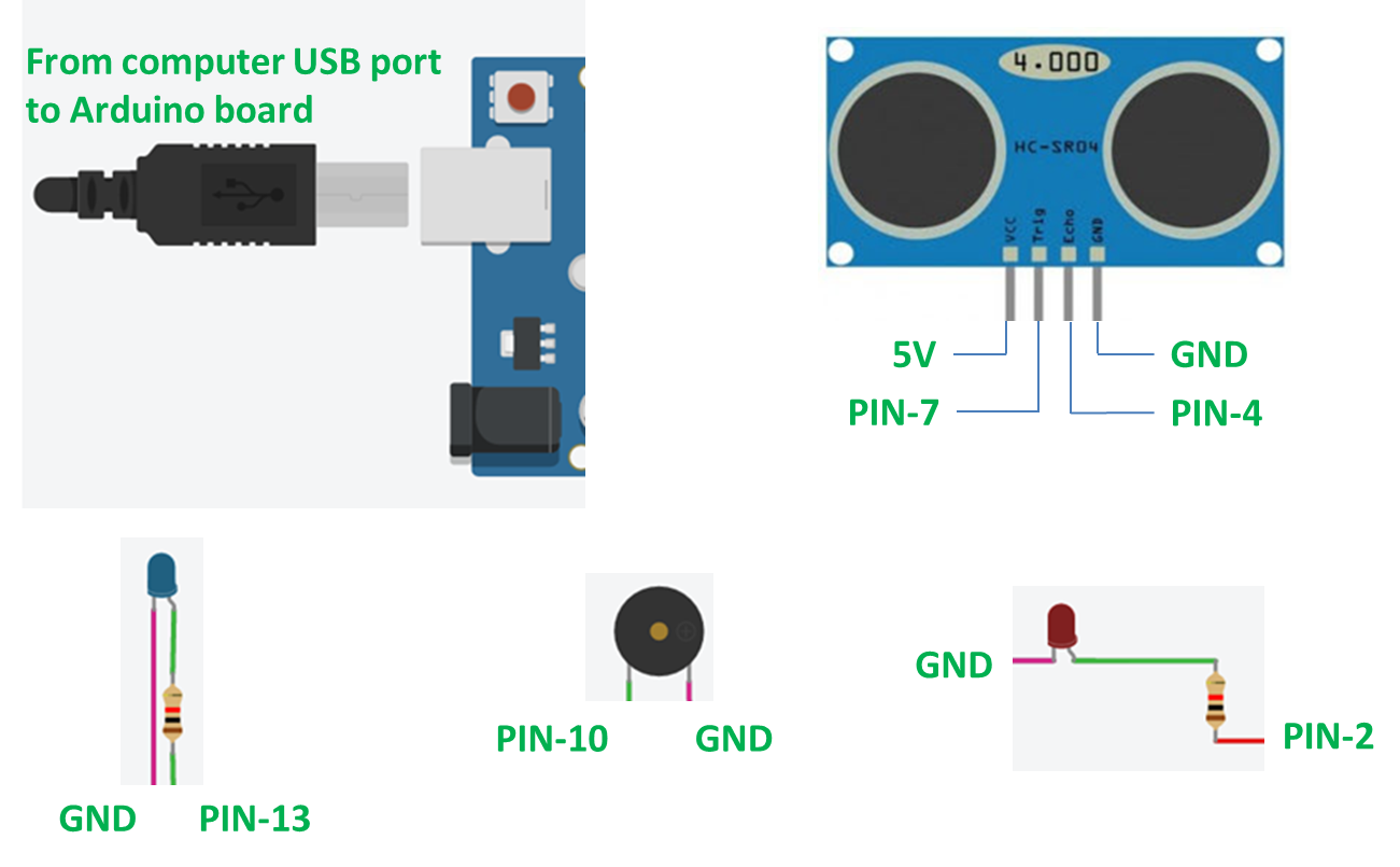
Schematics
Please follow this schematic to connect hardware to board and pin numbers.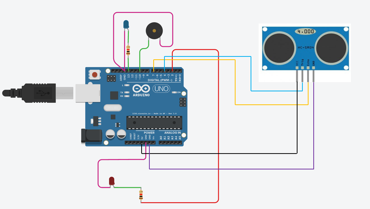
Manufacturing process
- Motion Detection Alarm System with Java & Reactive Blocks – Deploy on Raspberry Pi & Send SMS
- Arduino Uno-Based Human Detection Robot: Step‑by‑Step Sensor Integration
- SERENA: A Custom Arduino Mega 2560 Alarm System with TFT LCD Touchscreen
- Real‑Time Forest Fire Monitoring System with SMS Alerts
- Smart Basement Ventilation System: Arduino‑Powered Moisture Control
- Advanced Fall Detection System Using Arduino, Windows IoT, and Azure Cloud
- Detect Coughs with TinyML on Arduino Nano for Early Flu Detection
- Detecting Object Colors with Arduino Nano and TCS3200 Sensor
- Real‑Time Water Quality Monitoring System with Arduino & GPRS/GPS
- Arduino-Based Early Flood Detection System – Source Code & Circuit Design