


Arduino Sound Sensor with LED Indicators and LCD for Real-Time Sound Level Monitoring
Components and supplies
 |
| × | 1 | |||
 |
| × | 1 | |||
 |
| × | 1 | |||
 |
| × | 1 | |||
| × | 1 | ||||
 |
| × | 1 | |||
 |
| × | 1 | |||
| × | 1 | ||||
 |
| × | 2 | |||
 |
| × | 4 | |||
 |
| × | 2 | |||
| × | 4 | ||||
| × | 4 | ||||
 |
| × | 8 | |||
 |
| × | 4 | |||
 |
| × | 4 |
Apps and online services
 |
|
About this project
This project is about monitoring the sound level data that is being released, produced or outputted(?) by the speakers.
Aaah... this is a product of curiosity and boredom.
I used a [KY-038] microphone sound sensor module to pickup the values that I then gathered from the Serial Monitor, transferred to a spreadsheet, arranged to ascending order then chose the values that occurs more repetitively than others or just the ones that I like.
I picked a number of variables from the lowest range to the mid and high range.
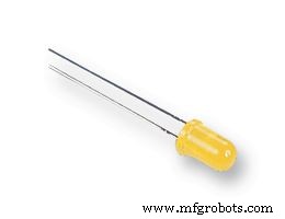
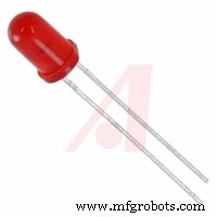
The variables from the lowest range of values will activate the Yellow LEDs, the mid range ones will activate the Green LEDs and the high range ones will activate the Red ones.
The LEDs will be activated or turned on when the certain sensorValue is reached or detected by the sound sensor.
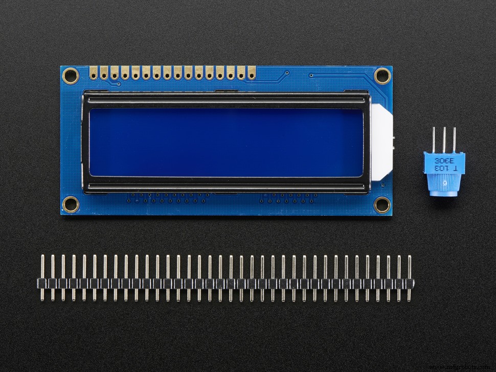
I also included an optional LCD to view the values in real time just for fun.
I basically just upgraded this code
Added some codes from here
And here
The LCD Codes are from my previous project
And Username MAS3's Comment here
I encountered a problem where the data that is appearing on the LCD have some leftover digits from the past sensorValue. Like, when the current value is supposed to be 619 which is what is on the Serial Monitor, but it becomes 6194, because the past value was 1234.
Download the .cpp and .h files here.
******************************************************************************
Social Media Links To Follow (I mean, if you want to):
Facebook - https://fb.me/HeathenHacks
Twitter - https://twitter.com/HeathenHacks
Instagram - https://instagr.am/HeathenHacks
******************************************************************************

https://drive.google.com/file/d/15NRocdFjr-DG7Hu2zyyvSvRz7bcncvU7/

Code
- SoundSensorLEDwData
SoundSensorLEDwDataArduino
I added comments on the code for some explanation. I hope I know what I'm doing. lol.#include "Arduino.h"
#include "LiquidCrystal_PCF8574.h"
#define LCD_ADDRESS 0x27
#define LCD_ROWS 2
#define LCD_COLUMNS 16
#define SCROLL_DELAY 150
#define BACKLIGHT 255
LiquidCrystal_PCF8574 LCDi2C;
//Add name and position of the LED bulb on the breadboard + Where it's connected on the Arduino.
// LED1 is LED Bulb 1 on the breadboard and 3 is Digital PWM 3 on the Arduino.
int LED1=3;
int LED2=4;
int LED3=5;
int LED4=6;
int LED5=7;
int LED6=8;
int LED7=9;
int LED8=10;
int soundSensor=2; // Digital Pin 2 on the Arduino is where the "DO" of the Sound Sensor is connected.
int sensorValue = analogRead(A0); //This is where the "AO" of the Sound Sensor is connected.
boolean LEDStatus=false;
void setup () {
Serial.begin(9600);
LCDi2C.begin(LCD_COLUMNS, LCD_ROWS, LCD_ADDRESS, BACKLIGHT); //These are the ones that we defined earlier.
pinMode(soundSensor,INPUT); //Because our Sound Sensor is an Input Device.
pinMode(LED1, OUTPUT);
pinMode(LED2, OUTPUT);
pinMode(LED3, OUTPUT);
pinMode(LED4, OUTPUT);
pinMode(LED5, OUTPUT);
pinMode(LED6, OUTPUT);
pinMode(LED7, OUTPUT);
pinMode(LED8, OUTPUT);
pinMode(sensorValue, OUTPUT); //sensorValue is declared as an output because it will be printed on the LCD and Serial Monitor.
}
void loop() {
int sensorValue=analogRead(sensorValue);
int SensorData=digitalRead(soundSensor);
if(SensorData=1){
if(LEDStatus==false){
LEDStatus=true;
Serial.println(sensorValue); //This will be printed on the Serial Monitor just to make sure that the data on the LCD is the same.
LCDi2C.setCursor(0,0); //This is to make the text not scroll up and disappear then reapper again when sensorValue data is being added.
LCDi2C.print("SoundLevel Data:"); //The text that will appear and stay on Row 1 of the LCD.
LCDi2C.setCursor(0,1); //This is to make the text not scroll up and disappear then reapper again when sensorValue data is being added.
LCDi2C.print(sensorValue); // The data that will appear on the LCD.
LCDi2C.print(" "); // This is to prevent extra digit from the past value appearing on current value. Like, when the past value is 1234, then the current is supposed to 619, but it appears as 6194.
}
if(sensorValue>=750) { // sensorValue greater than or equal to XX. XX numbers are gathered from the most recent data on the Serial Monitor. Copied and pasted it on a spredsheet, then arranged from the lowest to the semi highest sound volume level.
digitalWrite(LED8,HIGH); // You can use the different values from the sensor on each LED bulb if you want it to act like a sensor by displaying or lighting up corresponding LED bulbs according to the sensor values data.
} // Like Yellow LED bulbs will light up when the sensor picks up a low volume sound aka. Minimum volume level, Green LED bulbs light up when the Volume level is OK, and Red LED Bulbs light up when the volume hits the Loud volume threshold.
else{ // Alternatively, you can just add the same value to all the LEDs if you want all of them to react at the same time.
LEDStatus=false; // You can also play with the sensor values to make the LEDs dance. Rearranging the sensor values randomly for example. Or making 2 LEDs react at the same value and other LEDs react to other values.
digitalWrite(LED8,LOW);
}
if(sensorValue>=735) {
digitalWrite(LED7,HIGH);
}
else{
LEDStatus=false;
digitalWrite(LED7,LOW);
}
if(sensorValue>=725) {
digitalWrite(LED6,HIGH);
}
else{
LEDStatus=false;
digitalWrite(LED6,LOW);
}
if(sensorValue>=720) {
digitalWrite(LED5,HIGH);
}
else{
LEDStatus=false;
digitalWrite(LED5,LOW);
}
if(sensorValue>=715) {
digitalWrite(LED4,HIGH);
}
else{
LEDStatus=false;
digitalWrite(LED4,LOW);
}
if(sensorValue>=700) {
digitalWrite(LED3,HIGH);
}
else{
LEDStatus=false;
digitalWrite(LED3,LOW);
}
if(sensorValue>=675) {
digitalWrite(LED2,HIGH);
}
else{
LEDStatus=false;
digitalWrite(LED2,LOW);
}
if(sensorValue>=650) {
digitalWrite(LED1,HIGH);
}
else{
LEDStatus=false;
digitalWrite(LED1,LOW);
}
}
else{
LEDStatus=false; //Not really sure why I added this. Lol.
digitalWrite(LED1,LOW);
digitalWrite(LED2,LOW);
digitalWrite(LED3,LOW);
digitalWrite(LED4,LOW);
digitalWrite(LED5,LOW);
digitalWrite(LED6,LOW);
digitalWrite(LED7,LOW);
digitalWrite(LED8,LOW);
}
}
Schematics
Just follow the wires from end to end.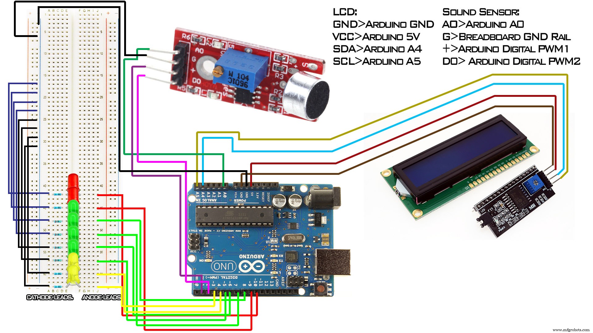
Manufacturing process
- Integrating Sensor Data into a Raspberry Pi: A Hands‑On Guide
- Arduino Nano Flight Simulator 2020 Control Panel – LCD & CDI Display
- DHT11 Temperature & Humidity Sensor Project with LED Indicators and Piezo Speaker
- Audio Data Transmission with Arduino Nano 33 BLE Sense
- Arduino Ultrasonic Distance & Temperature Monitor with LCD Alarm System
- Arduino Temperature Sensor Project: Read, Convert, and Display Fahrenheit
- Contact‑Free Faucet with Door‑Activated Control – Safe & Smart COVID‑19 Solution
- Real-Time Soil Moisture Monitoring with LCD Display – Arduino DIY Kit
- Build an IR Sensor Project with Arduino UNO – Simple Guide
- Portable Arduino-Based Temperature & Humidity Monitor with 16x2 LCD Display