


ArduRadio Alarm Clock: DIY Arduino-Based FM Radio & Alarm System
Components and supplies
 |
| × | 1 | |||
| × | 1 | ||||
| × | 1 | ||||
 |
| × | 1 | |||
 |
| × | 1 | |||
 |
| × | 1 | |||
 |
| × | 1 | |||
 |
| × | 6 | |||
 |
| × | 1 | |||
 |
| × | 1 | |||
 |
| × | 1 | |||
| × | 1 | ||||
 |
| × | 1 |
About this project
This is the evolution of the "Alarm Clock" (https://create.arduino.cc/projecthub/Tittiamo/alarm-clock-f61bad) with the addition of the radio (TEA 5767)
Navigating the Web I found a beautiful project of an FM radio with Arduino (https://www.instructables.com/id/Make-an-Arduino-FM-Radio-using-TEA5767/#CLPEZERIX0PVJW6), and since I like music I decided to update my "Alarm Clock".
TEA 5767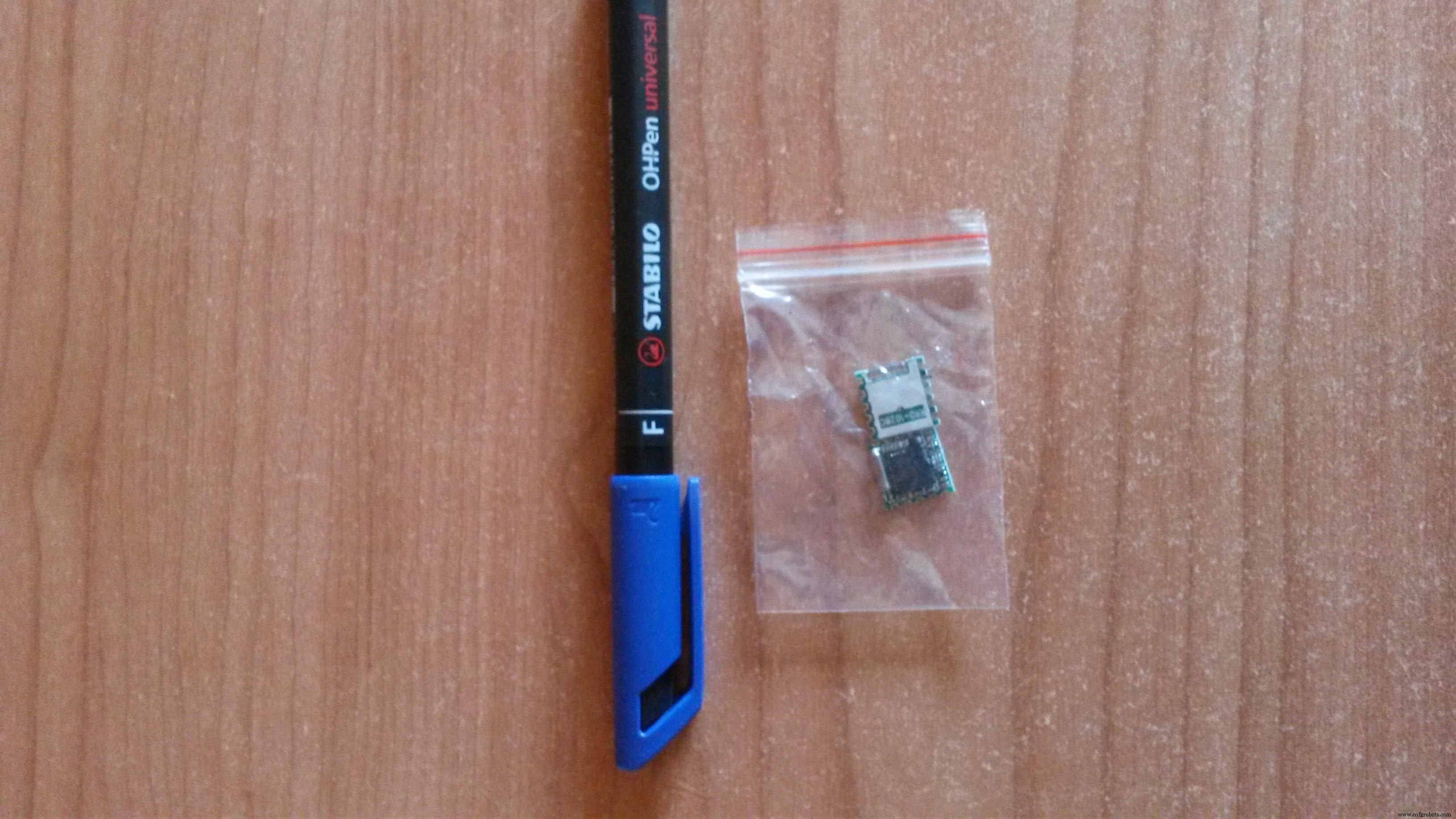
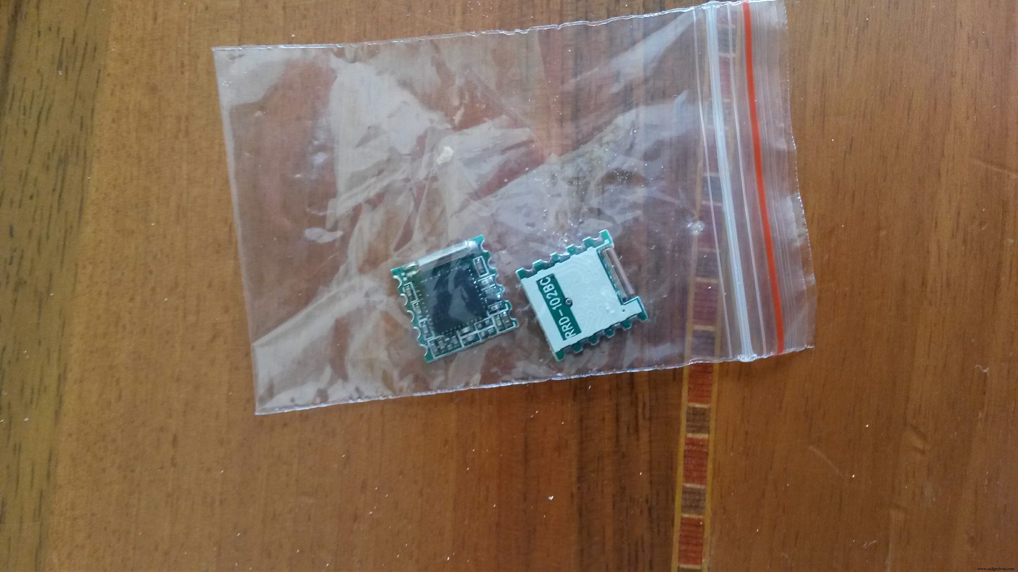
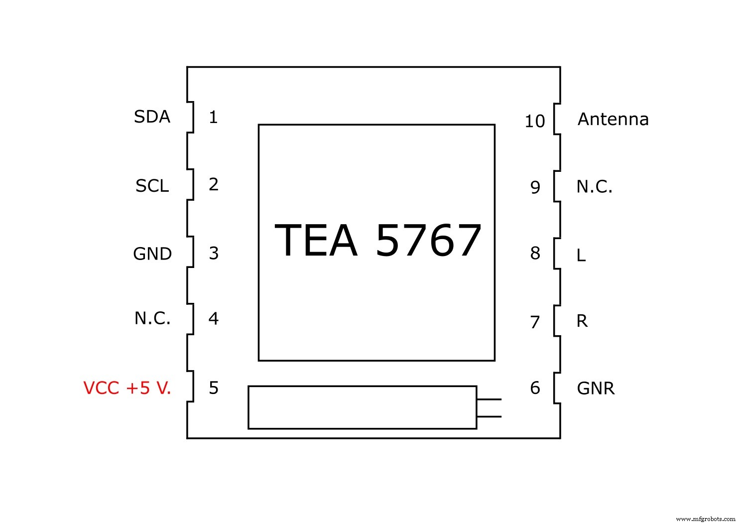
The "TEA 5767" card, purchased for a few € on Aliexpress, carries out most of the work, is connected to Arduino to pin A4, A5 (protocol I2c) and a Stereo TDA 7297 amplifier.
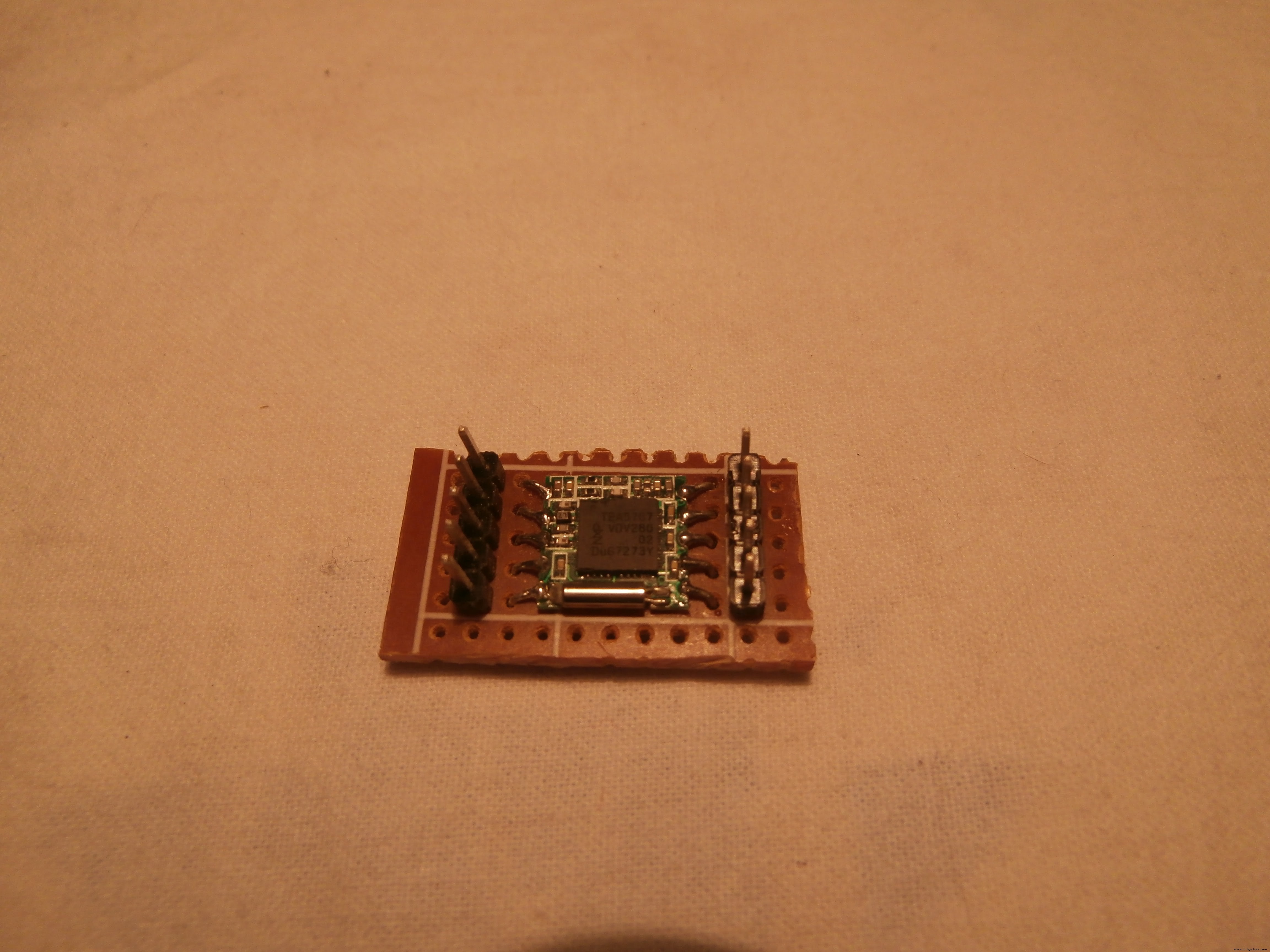
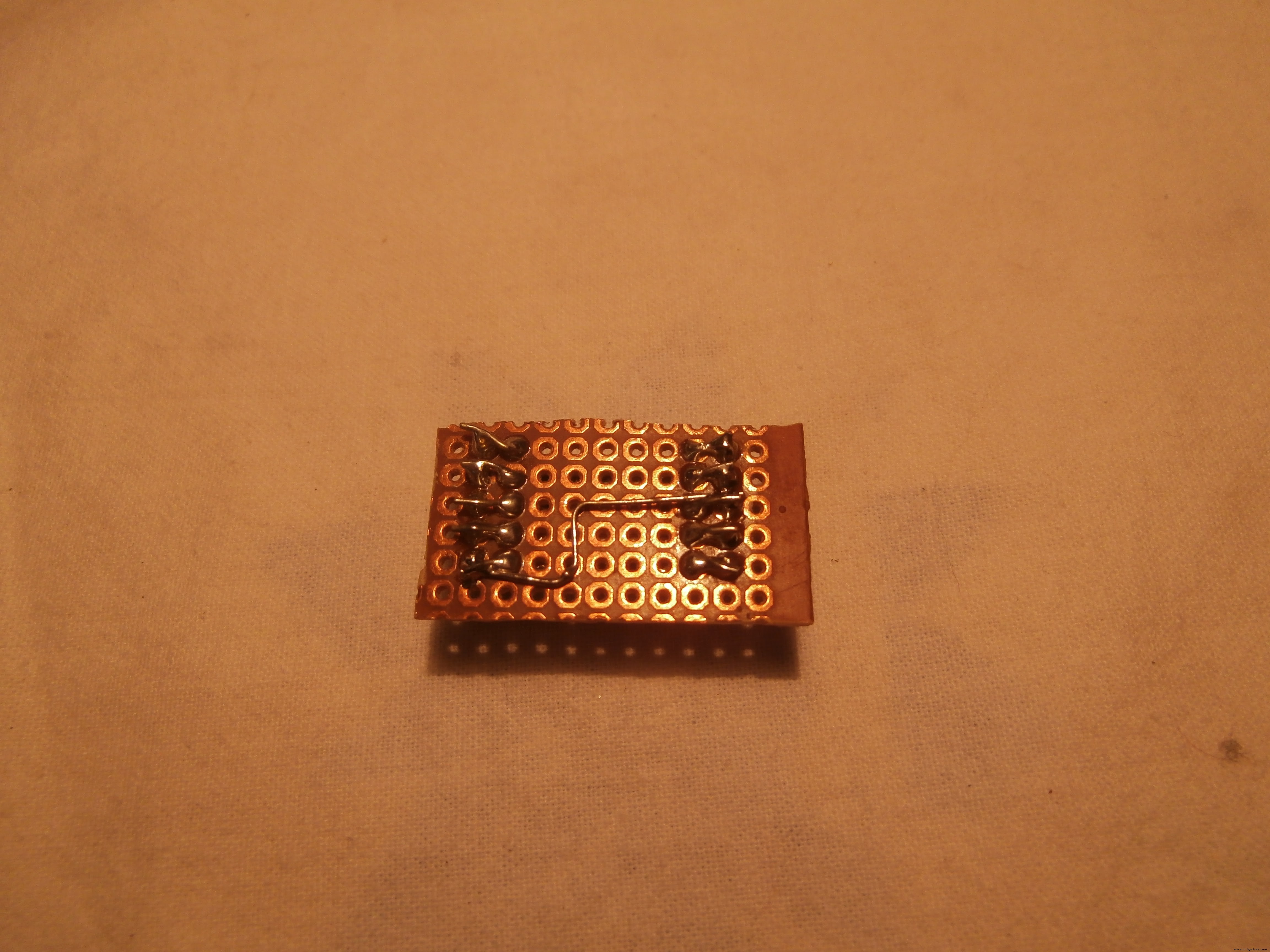
The TEA 5767 is very small and I had to do a lot of effort to fit a card with a thousand holes
Scheme
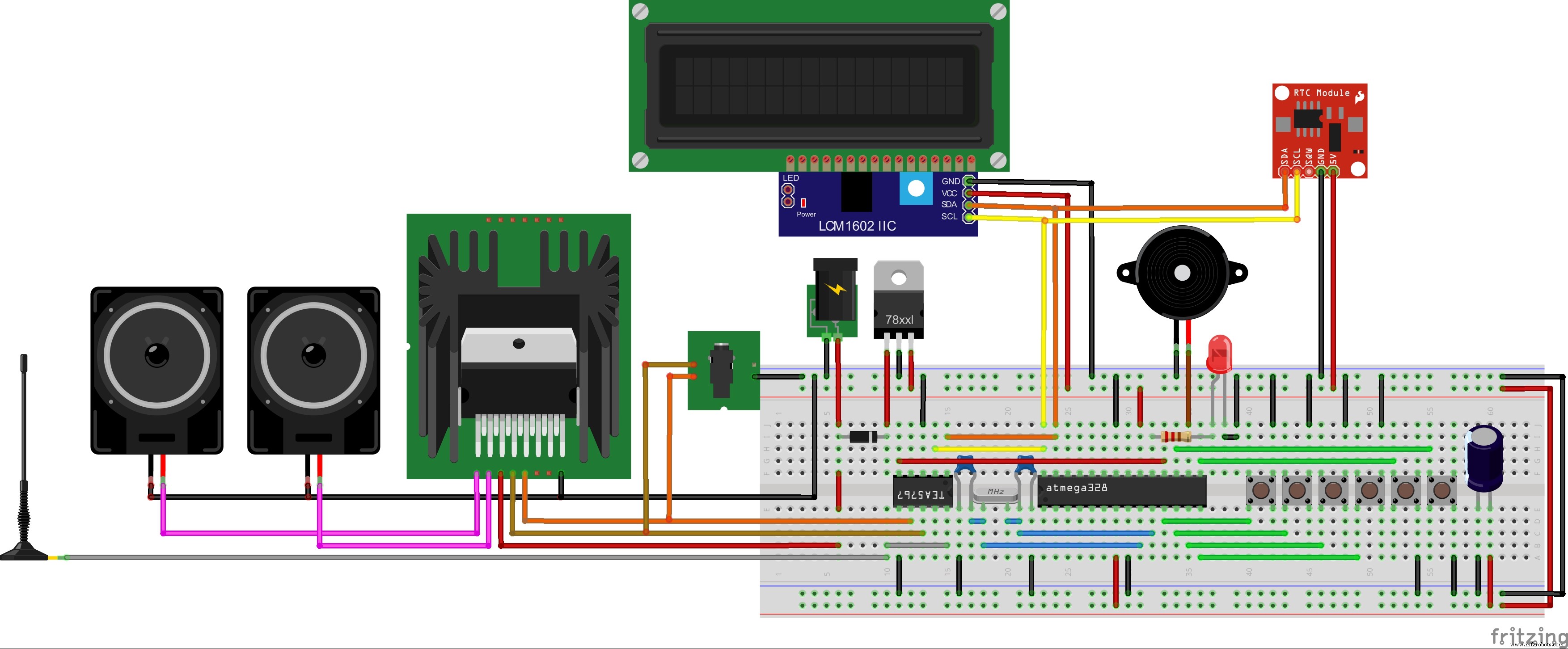
I took a lot of inspiration from the project "erik12892" but I also made several changes.
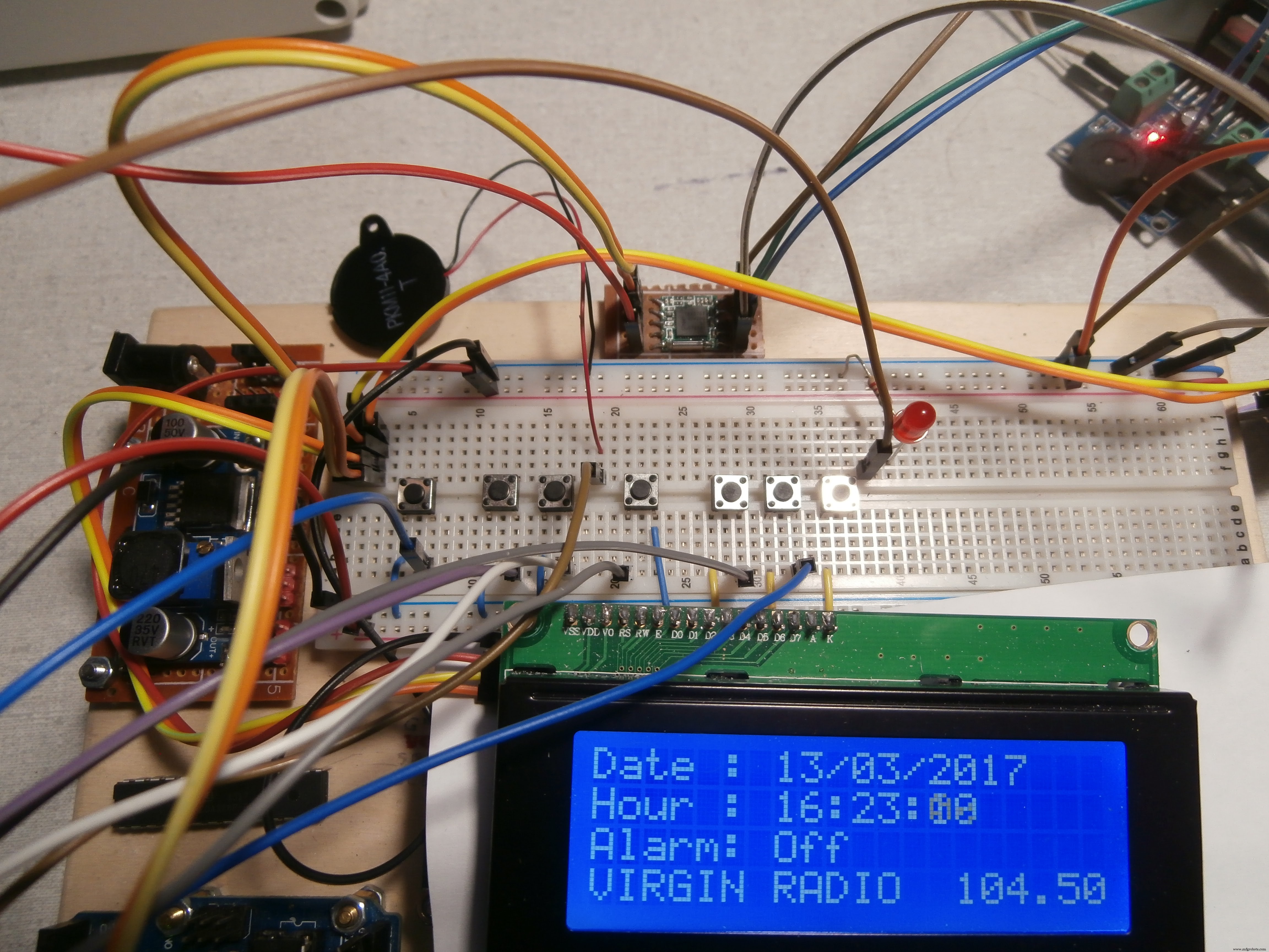
In addition to the P1, P2, P3, P4 buttons on the Alarm Clock, I have added 2 more than I need:
• P5 to change stored stations, I have only entered 4, but you can increase, it by changing the code a bit
• P6 since the TEA 5767 card consumes very little current, has been used to turn the radio on or off via Arduino, in order to use an auxiliary input (mp3, phone, etc.)
To change the radio frequency, use the buttons P2 = More, and P3 = Less.
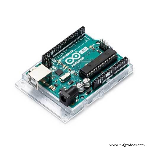
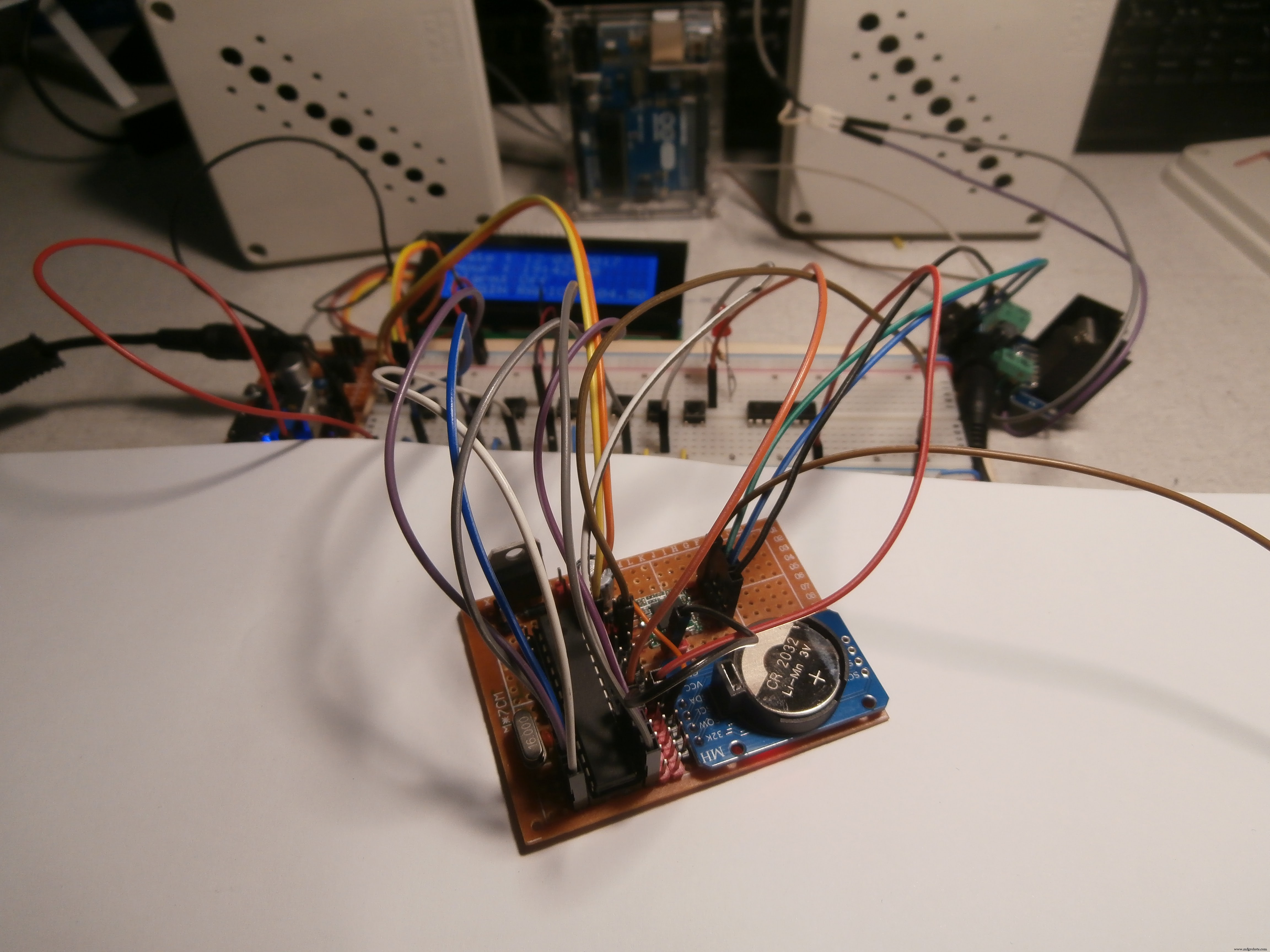
To stay low with the measurements, I built an Arduino Standalone.
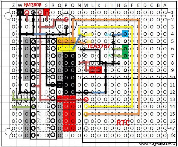
I enclose the electrical diagram, the Fritzing scheme and the PCB drawn in EXCEL.
Construction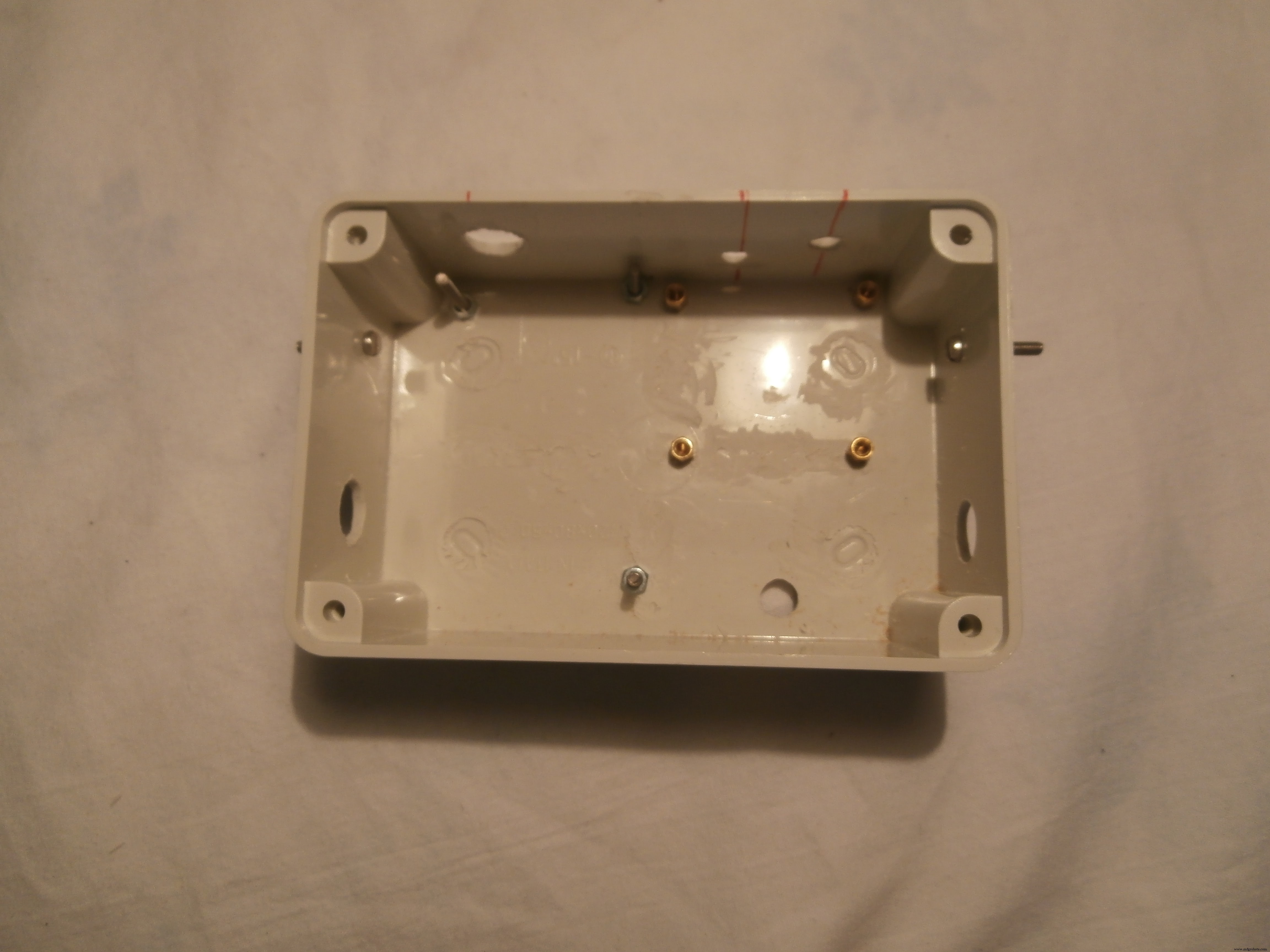

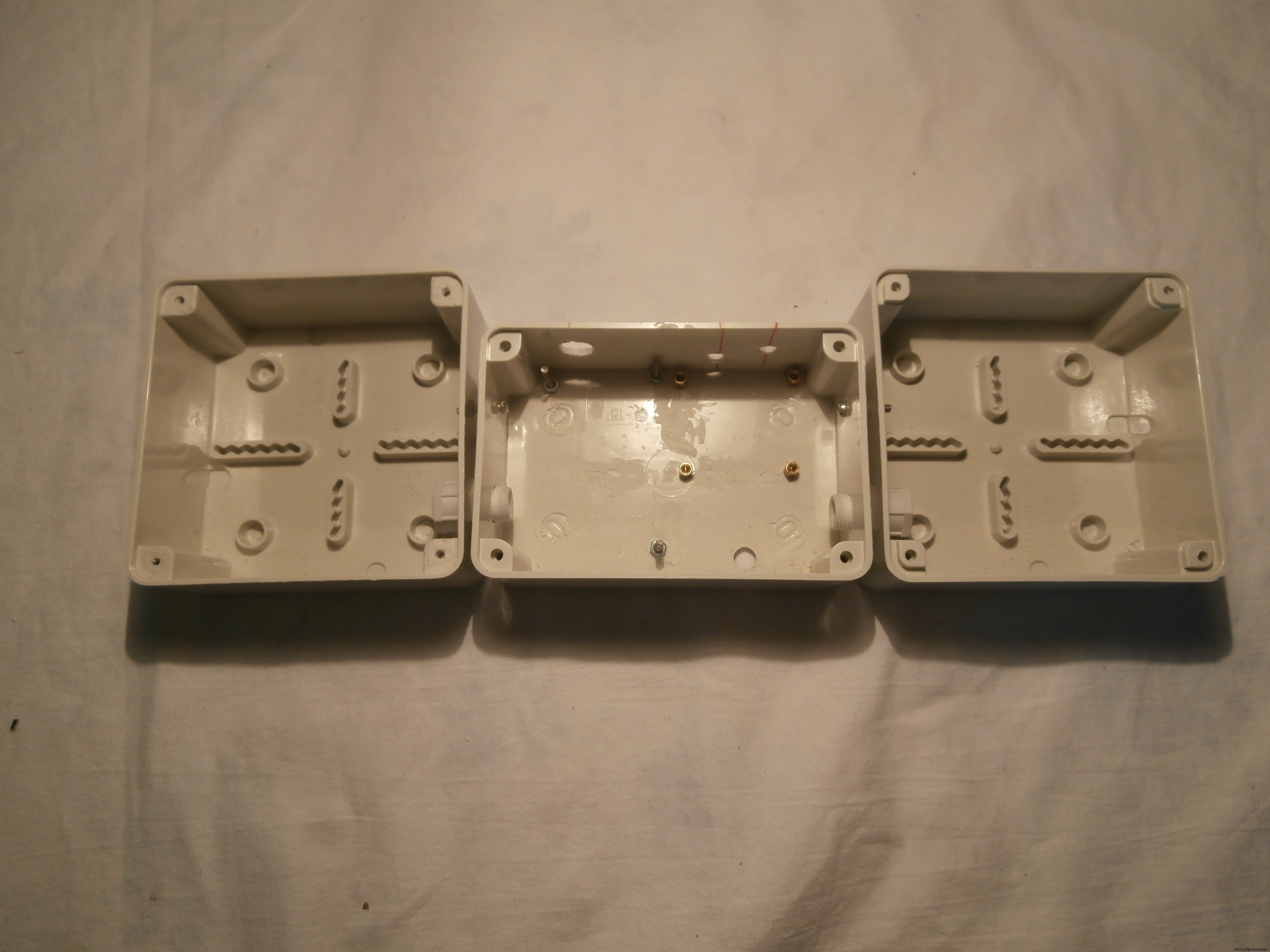
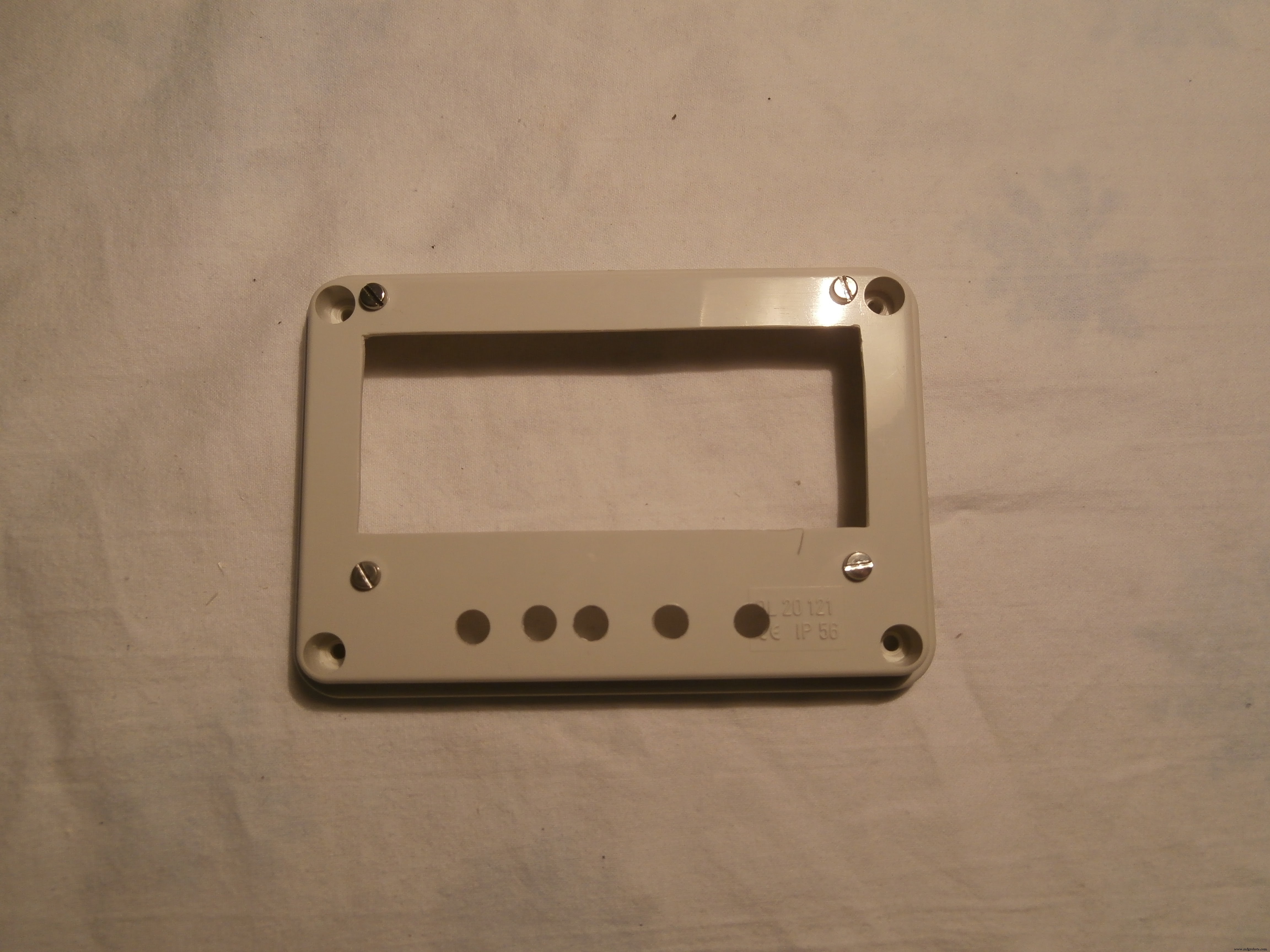


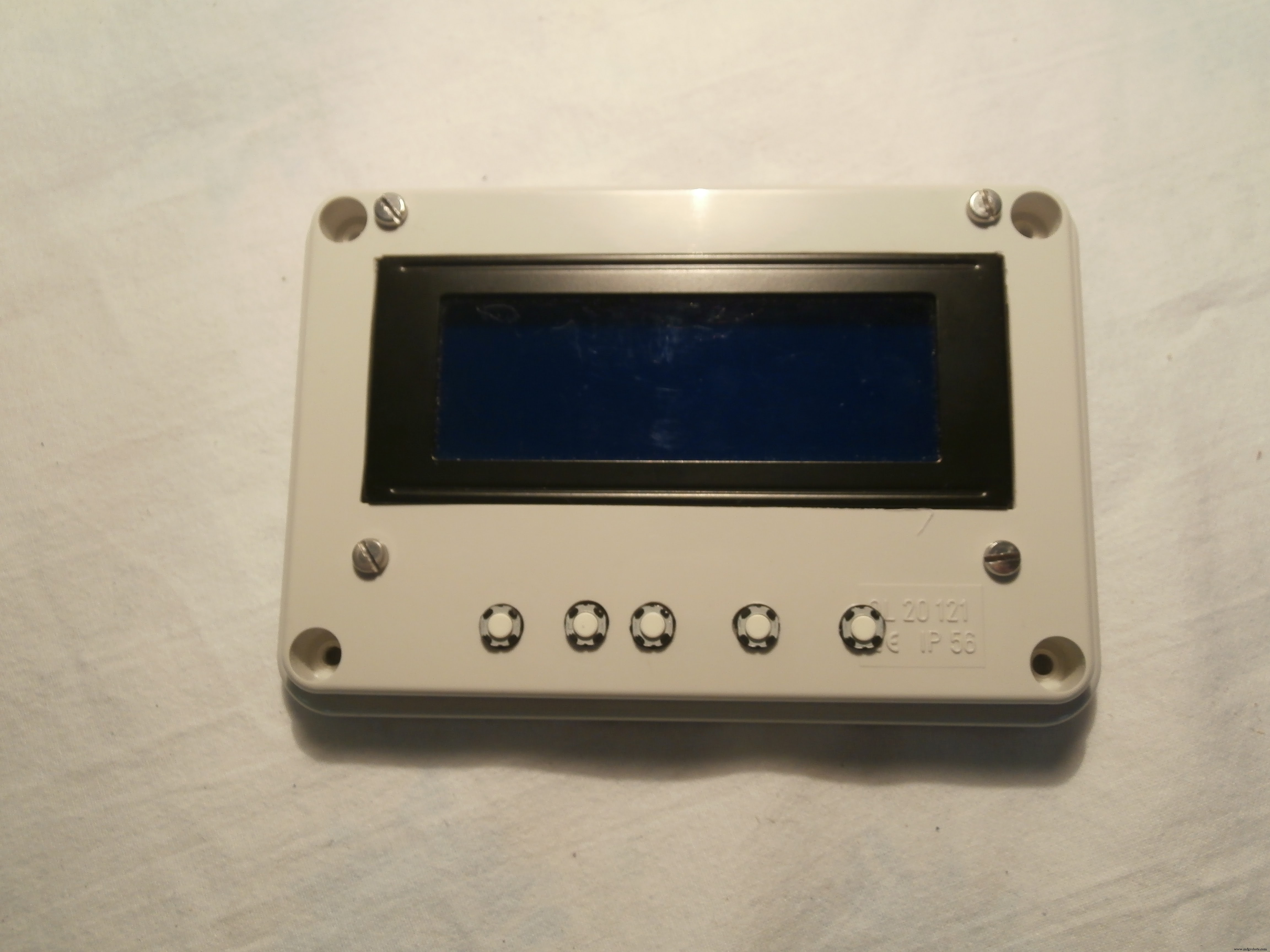
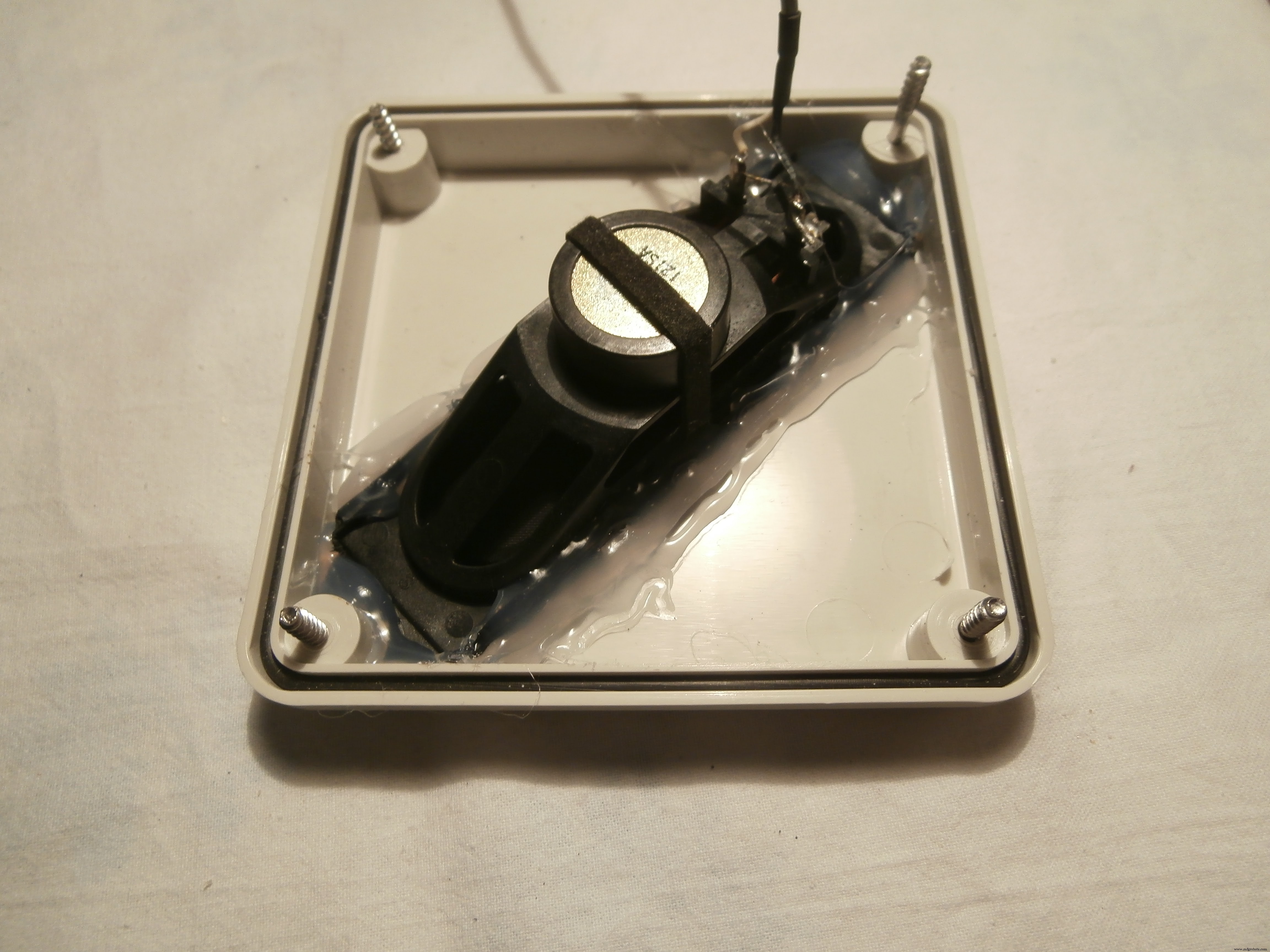
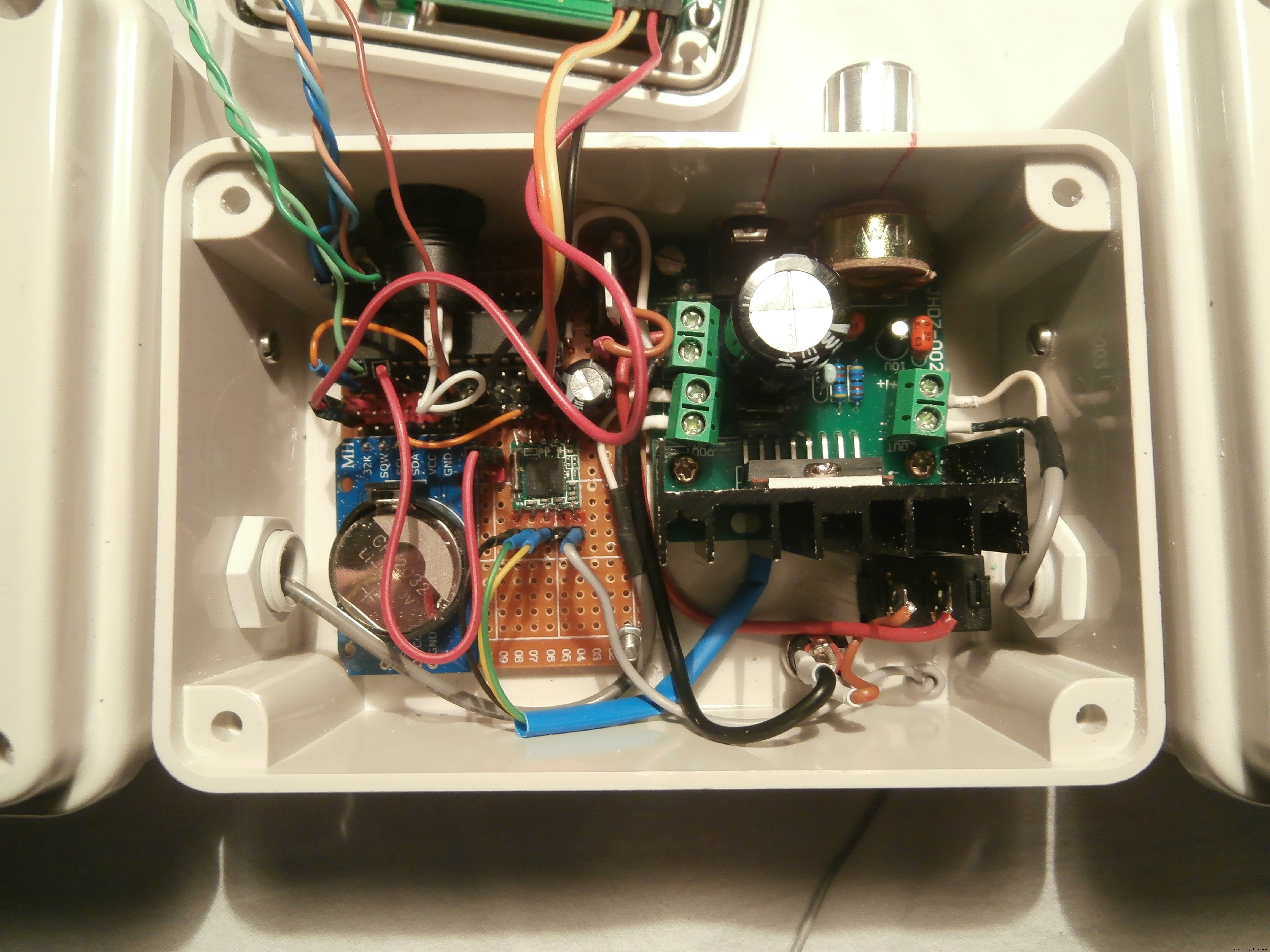
As with many of my designs,I used the electrical junction boxes, there are different sizes and shapes, I used a 120 x 80 x 50 mm for the container and two 100 x 100 x 50 mm for the speakers.
The speakers were recovered from an old cathode-ray monitor
The 3 boxes have been joined by cable glands and M3 screws.
Test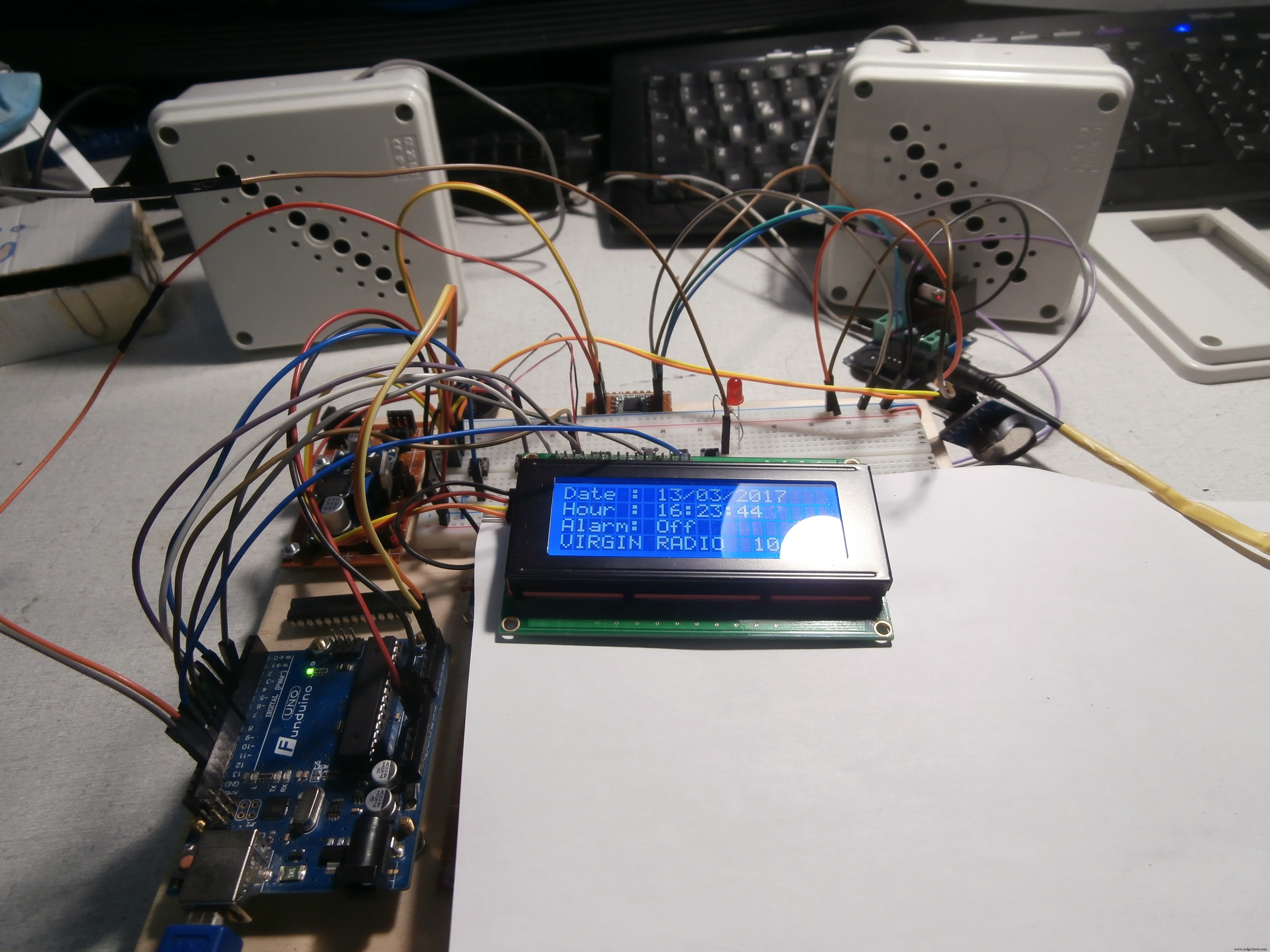
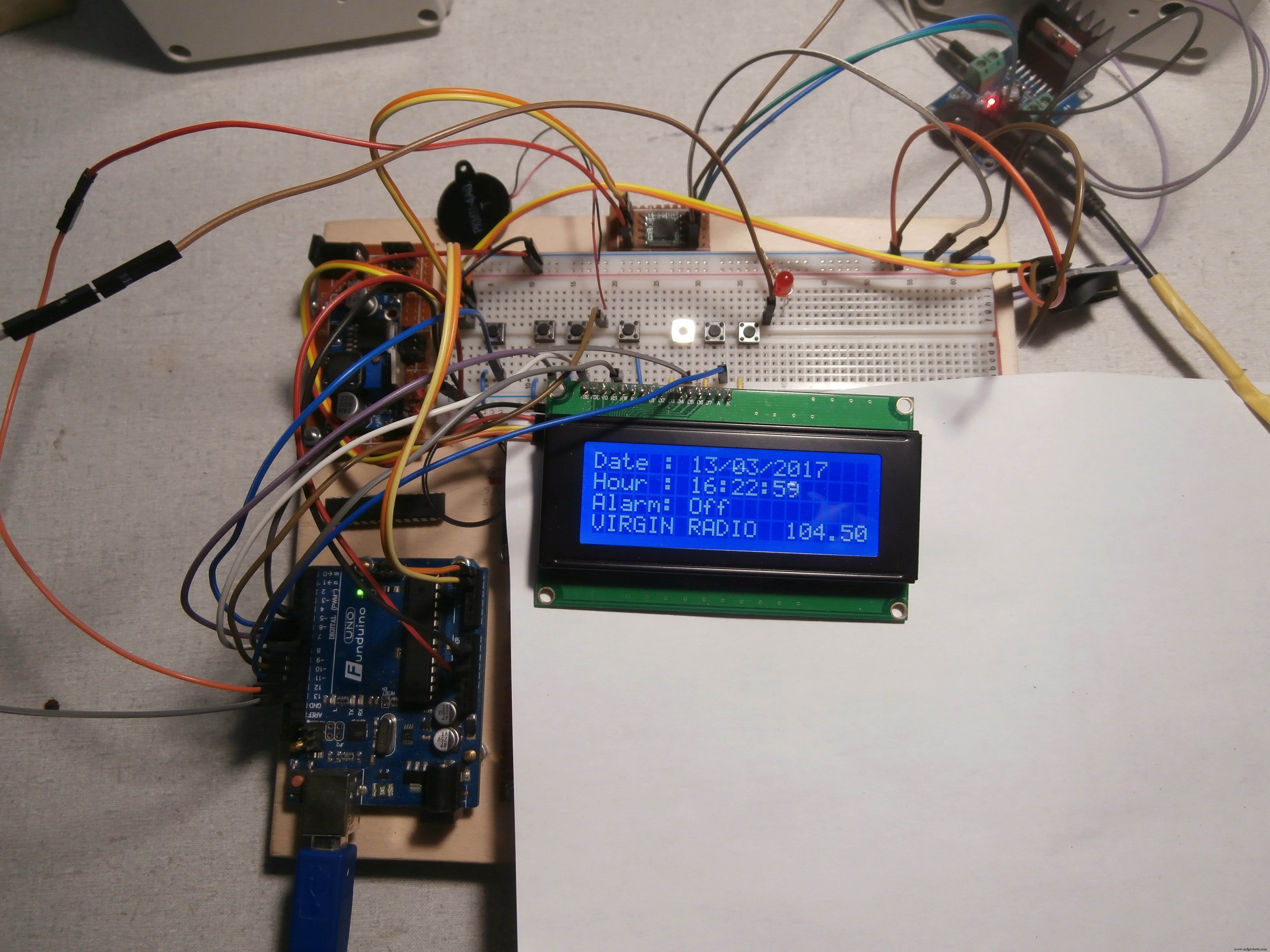
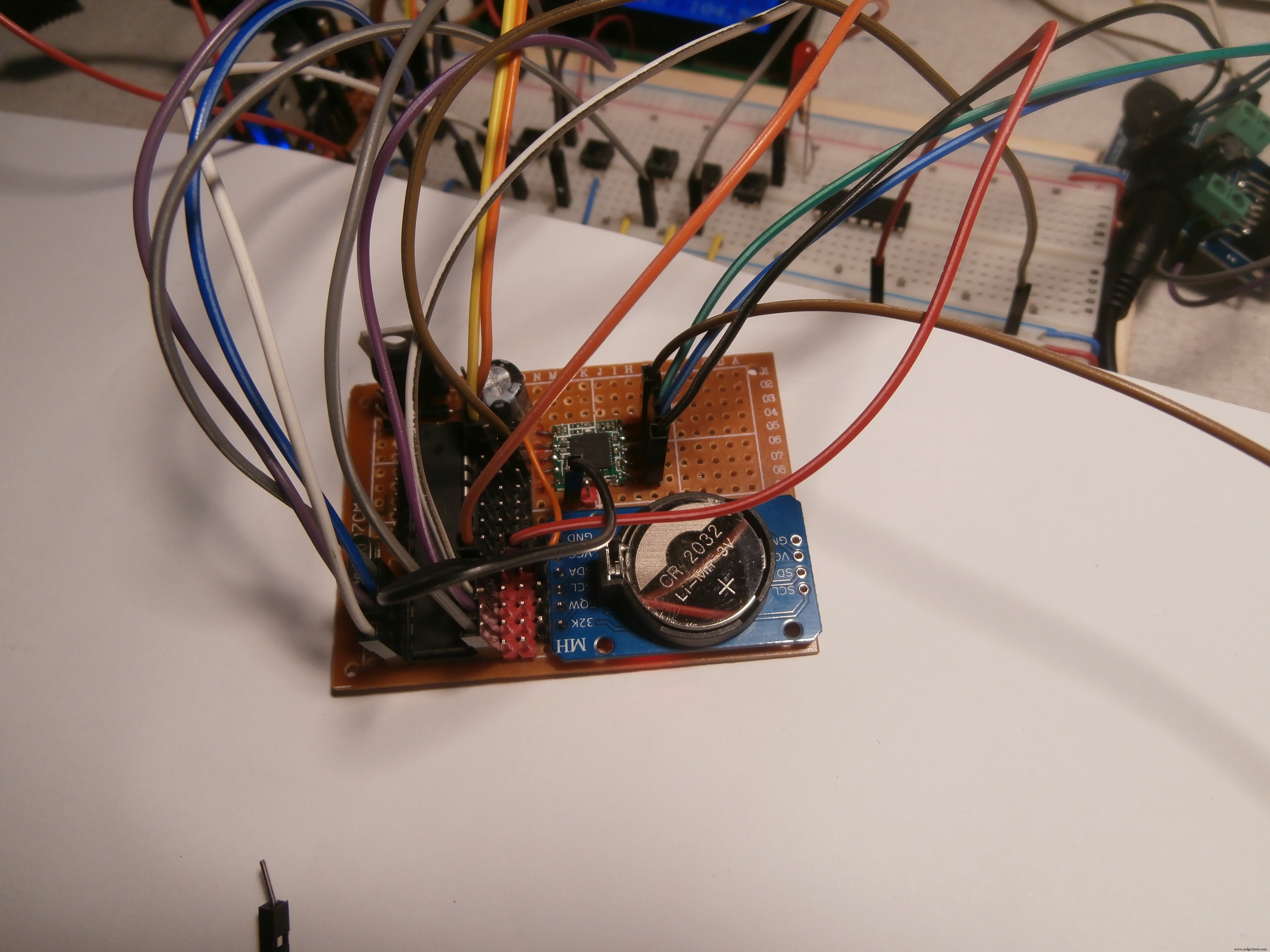
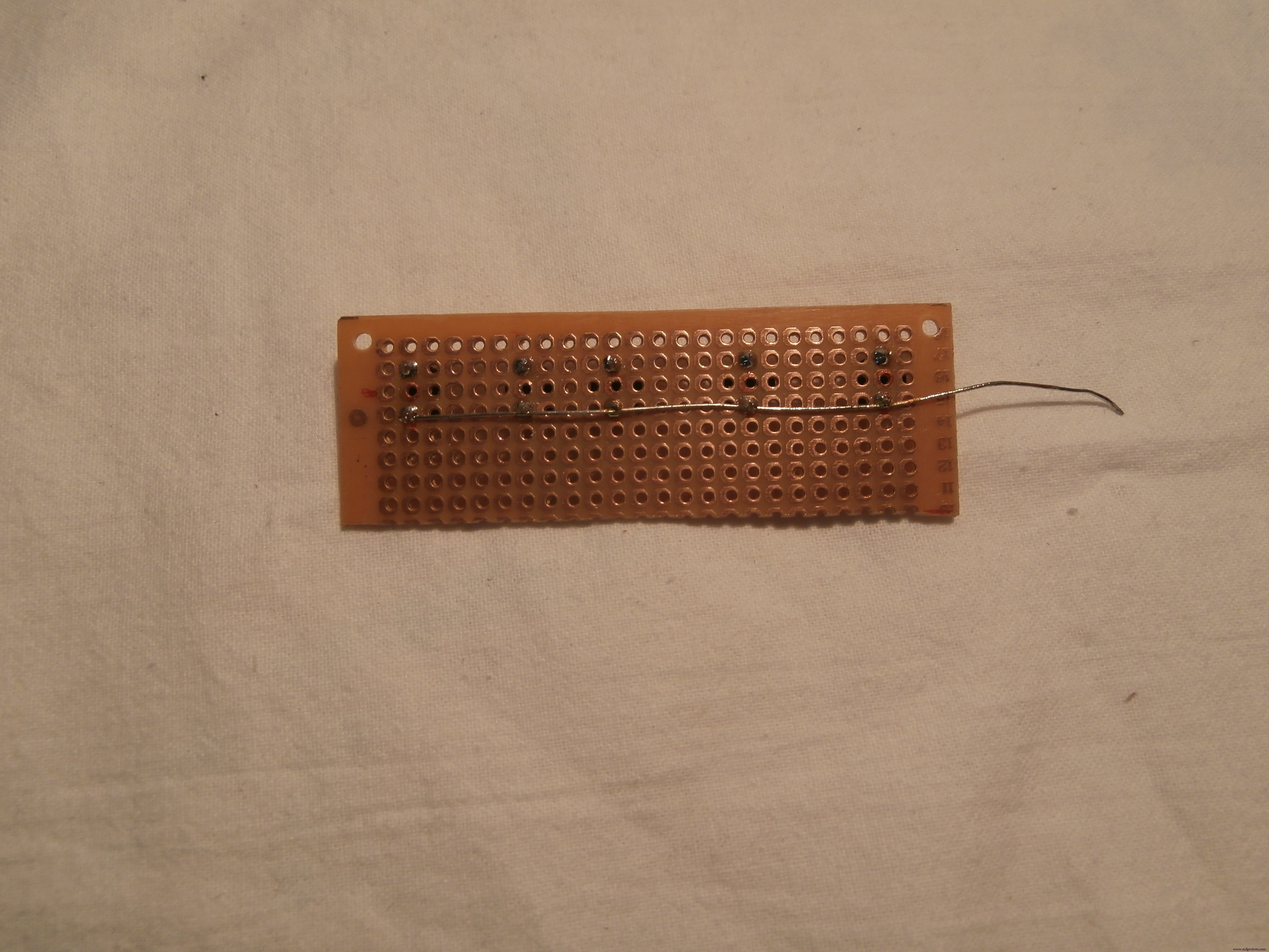
Before building the PCB, and putting it all in the box, I did several tests with the prototype chopping board.
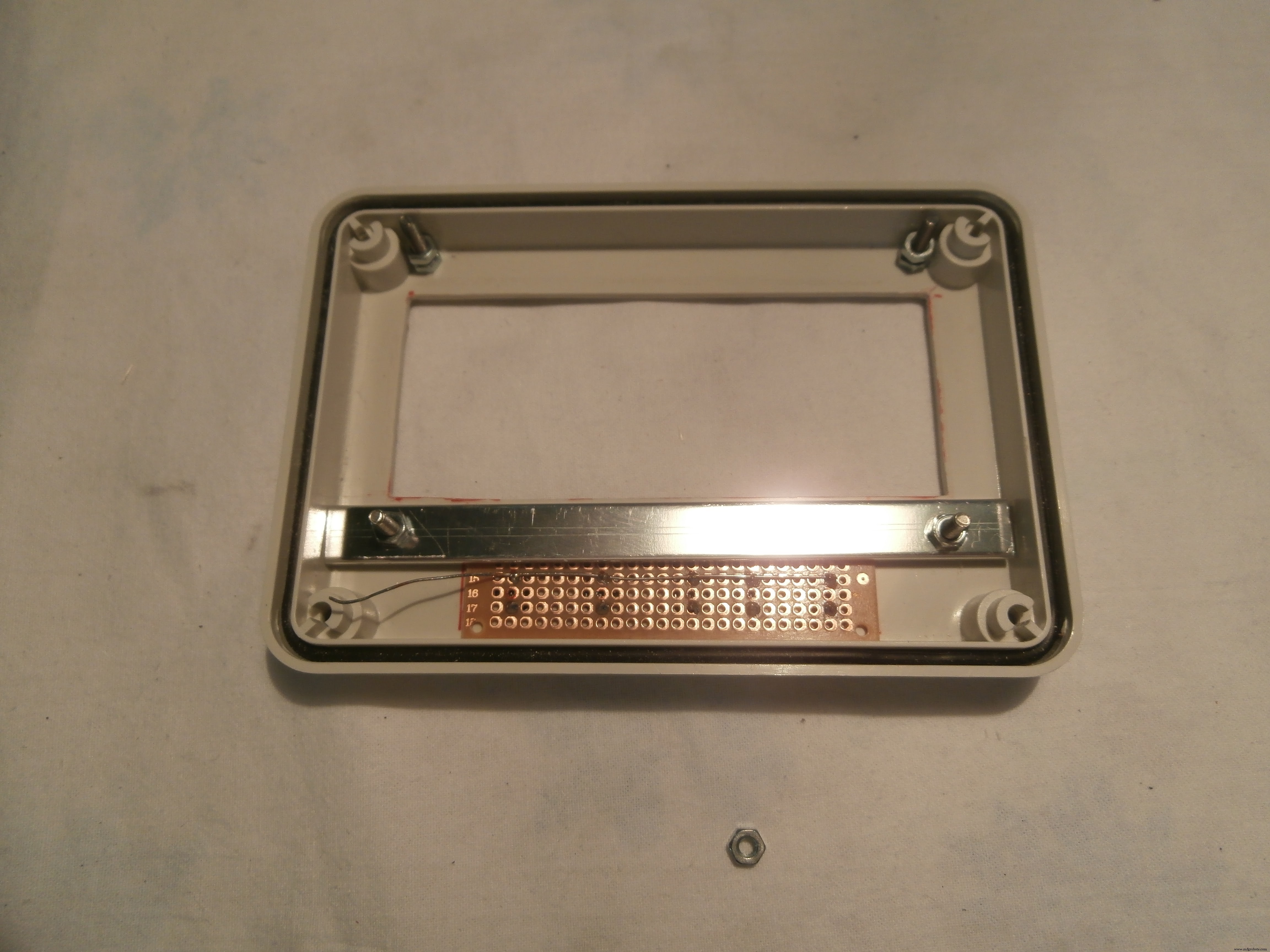
Assembling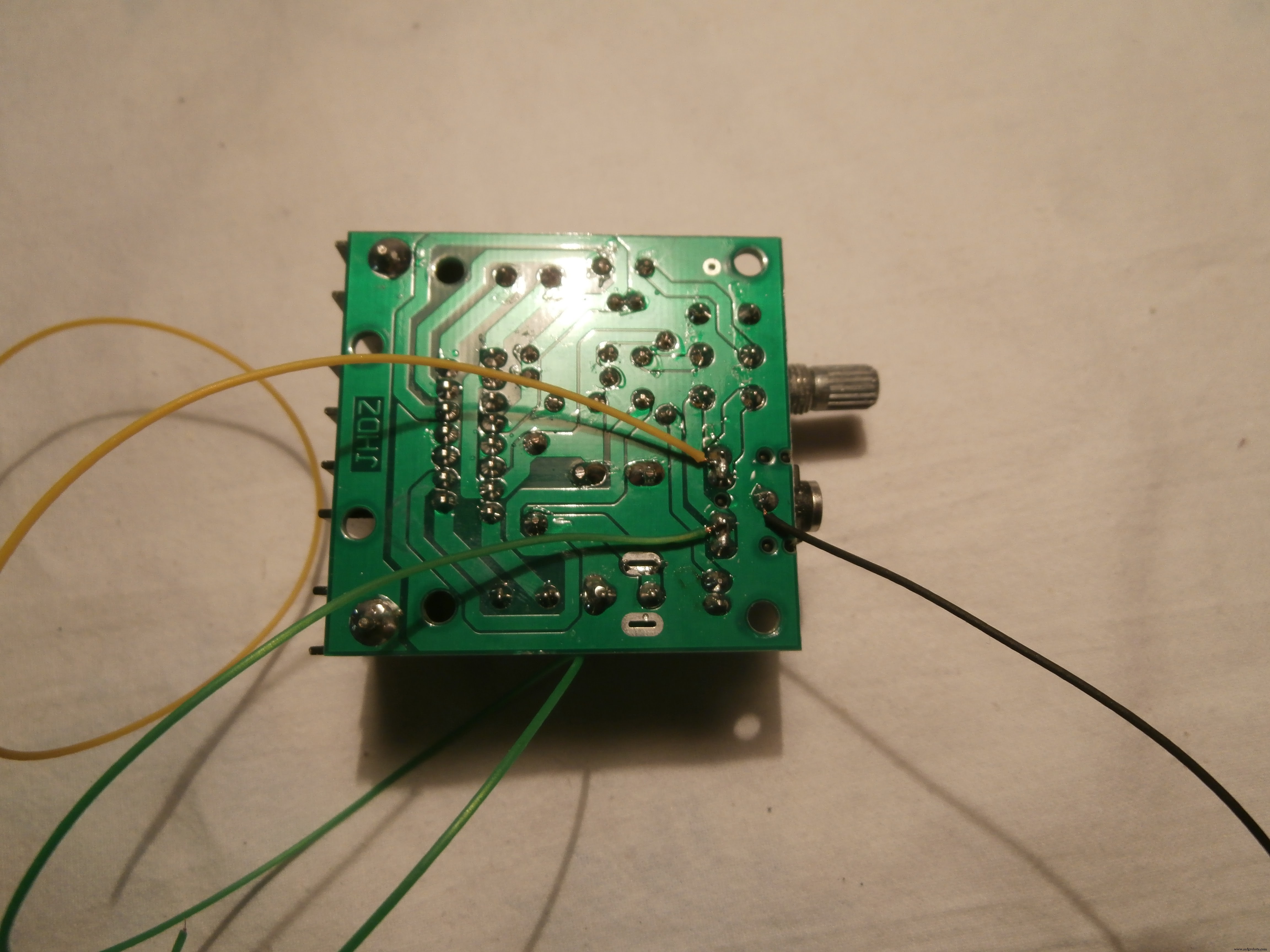


Three wires were welded to the amplifier to be connected to the TEA 5767 to respective L, R, and GRD
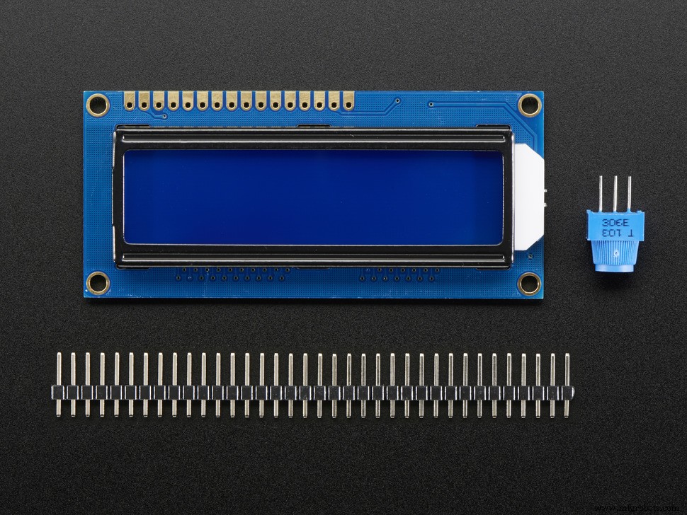
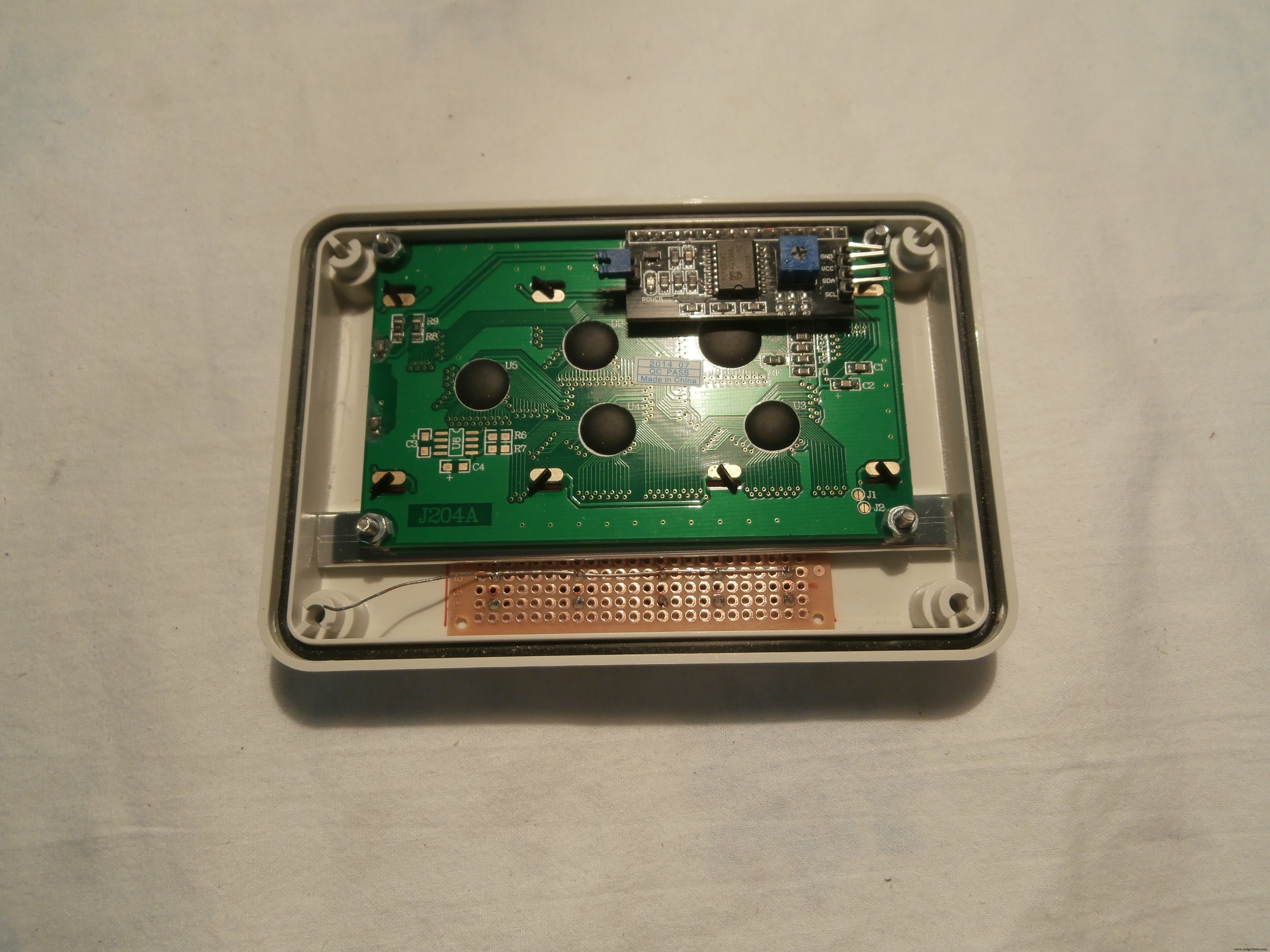
Arduino, TEA5767, Amplifier, Buttons, and Display, everything was assembled as from attached pictures.
As an antenna I used an electric wire up to 30 centimeters
Arduino CodeCode < here > or see below
Libraries:
Wire.h: from Arduino IDE
RTClib.h (https://github.com/adafruit/RTClib)
LiquidCrystal_I2C.h (https://github.com/fdebrabander/Arduino-LiquidCrystal-I2C-library)
TEA5767Radio.h (https://playground.arduino.cc/Main/TEA5767Radio)
Code
Arduino Code
Schematics
arduradio_Pjm09lDBgs.fzz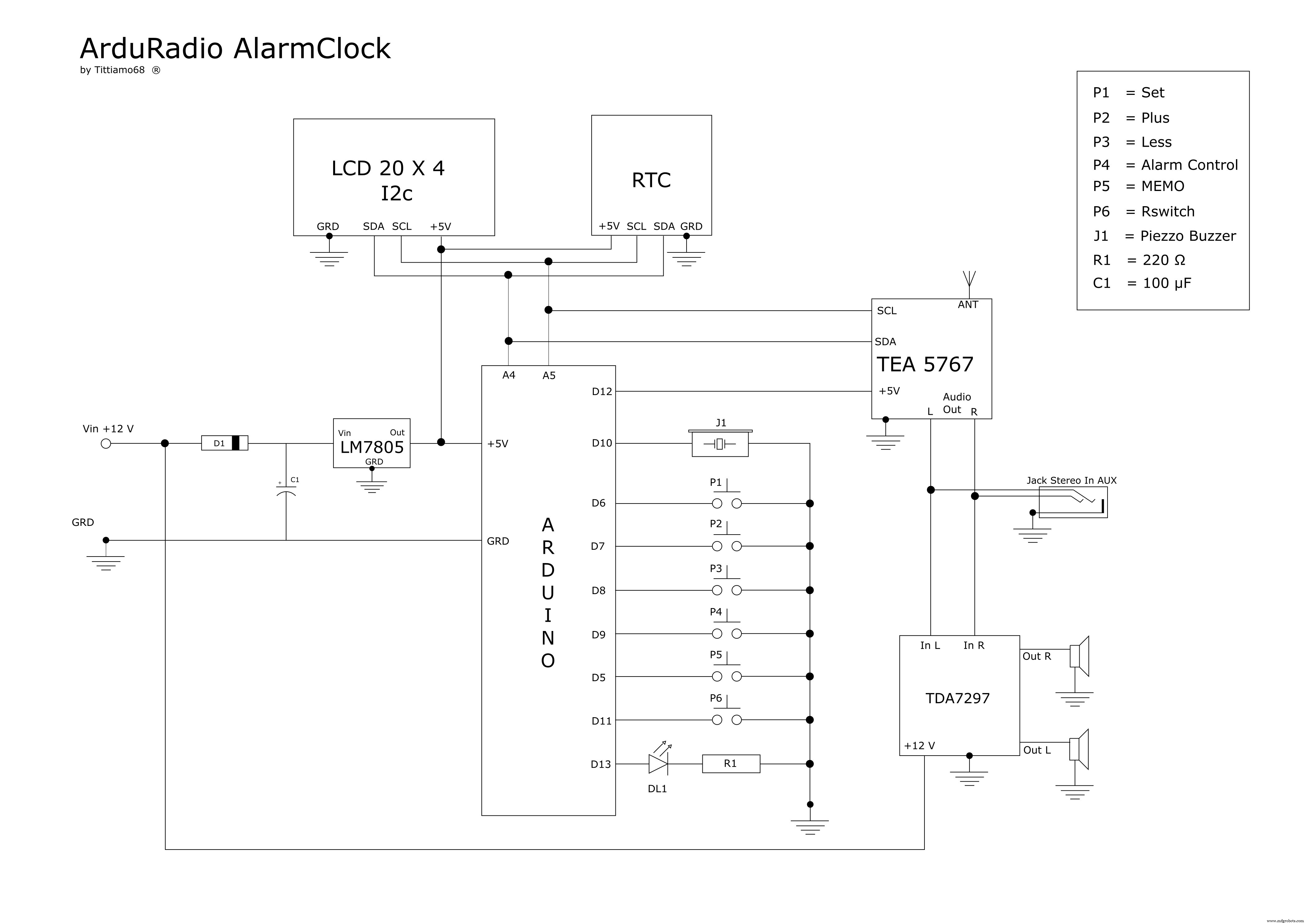
Manufacturing process
- Capture Water Droplets in Action Using Arduino Nano – DIY High-Speed Photography
- JX Wave Generator – Arduino-Compatible DDS Oscillator with OLED Display
- Build a DIY VR Skateboard with Arduino, Google Cardboard, and Bluetooth
- u-blox LEA‑6H 02 GPS Module: Arduino & Python Integration Guide
- Build a GPS Destination Notifier with Arduino UNO & NEO‑6M Module
- Integrate SIM800L GPRS Module with Arduino Using AT Commands
- Arduino Due Project Kit: TFT, GPS, RTC, Sensors, Bluetooth & Joystick – Full Component List
- Master the nRF24L01: Wireless Communication, Arduino Integration, Circuits & Code Guide
- Build Reliable Long‑Range Arduino Networks with the HC‑12 Module
- Master Arduino Bluetooth: HC‑05 Module Tutorial for Smartphone & PC Control