


Build a Custom Throttle Quadrant & Trim Wheel for MS Flight Simulator with Arduino Leonardo & 3D Printing
Components and supplies
 |
| × | 1 | |||
 |
| × | 3 | |||
| × | 1 |
Necessary tools and machines
 |
| |||
 |
|
Apps and online services
 |
|
About this project
IntroductionHaving recently upgraded my PC to enable it to run MS FS2020, I was inspired to improve the controls I was using. A keyboard does not really have the right feel for flying and I wanted to upgrade the experience to something better. I am not a full-time flight simmer and cannot afford the space or money to dedicate a lot to making a full cockpit or even a purchased set of controls.
I set about designing a set of controls in CAD that could be made with the tools I have and give a reasonable experience of what I imagine a real plane would feel like, I have never touched the controls on a plane so it is based on what I think they would be like.
I decided that the controls I would like are some single levers for throttle, flaps, landing gear and an elevator trim wheel. I mostly fly the small light single engine planes in the sim so that is what I was focusing on.
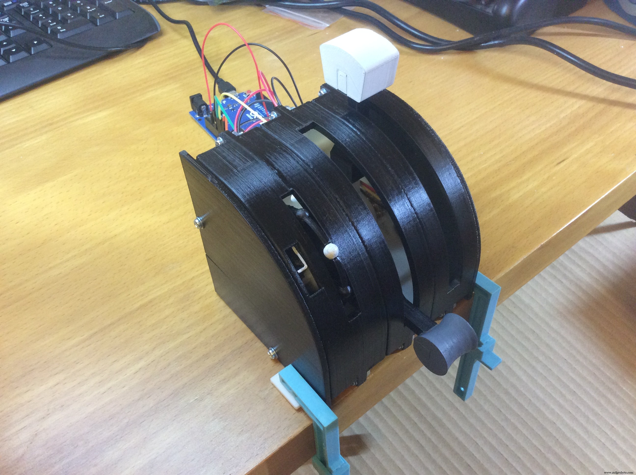
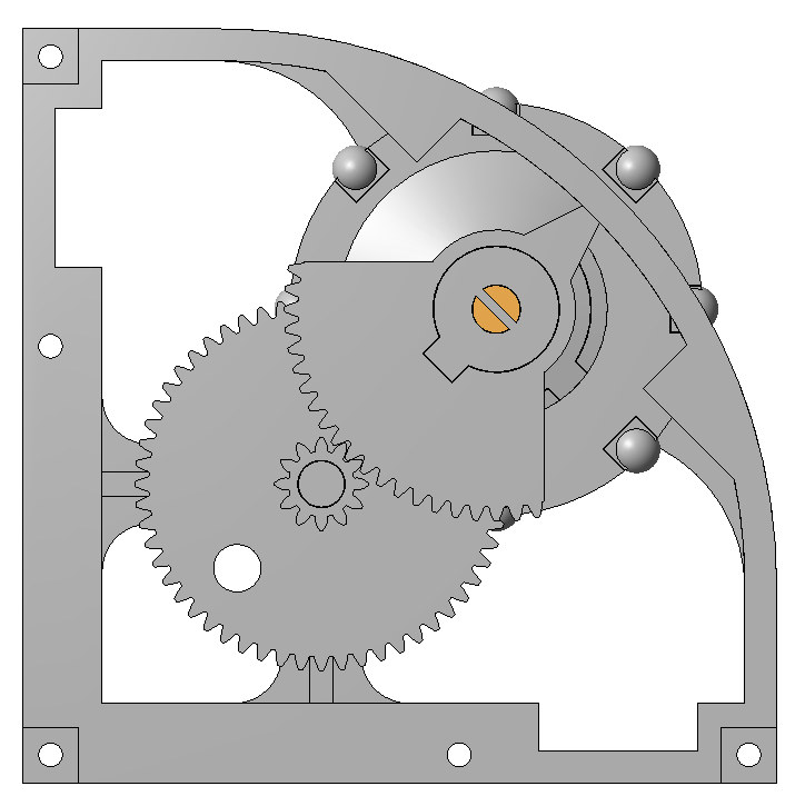
The trim wheel was the most challenging to design and it took several sketched ideas over many days to come up with a design that I thought would provide the look and feel that I wanted.
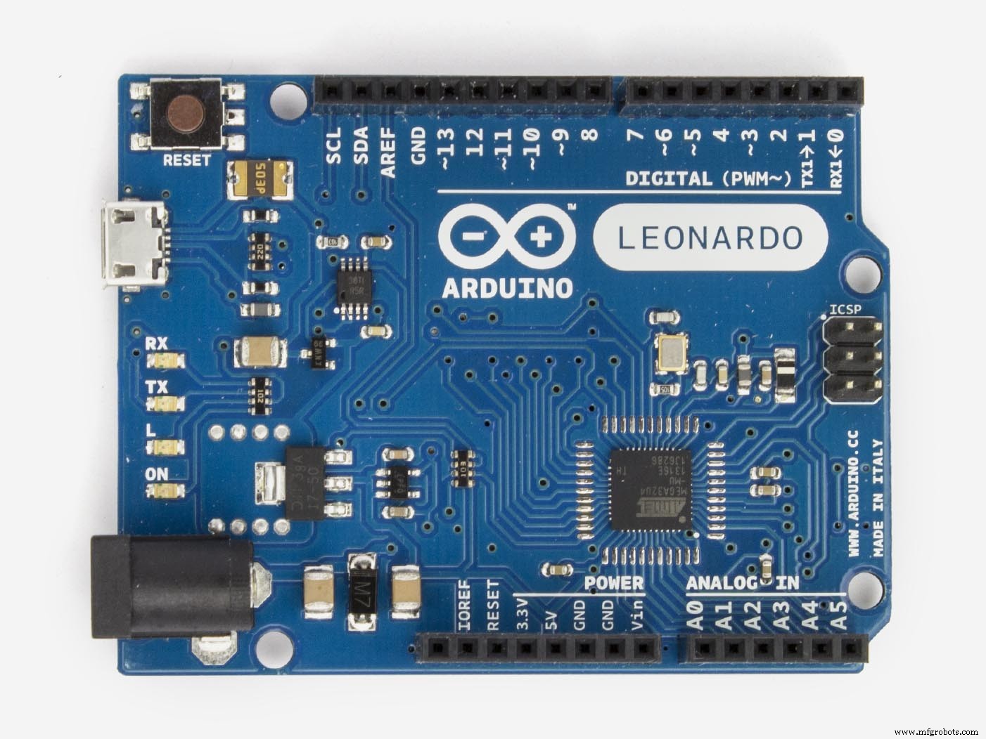
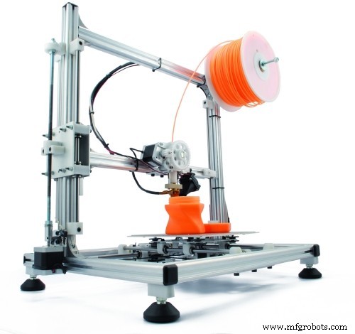
All the parts were 3D printed in ABS on my UP! printer, they were then painted and wired up to an Arduino, a Leonardo to start with then swapped over to a Micro. To end up with a plug and play unit which can be stored away easily when not in use.
Parts3D Printed Part List
Each lever module will require
Each wheel module will require
Back box parts can be used to house the Arduino and wiring.
ConclusionA very enjoyable build, very easy from a coding point ofview, the real challenge in this build was the design, especially the trim wheel and getting the feel right.
Code
- Quadrant.ino
Quadrant.inoArduino
Use the setting variable and the serial monitor to find the end point values for each potentiometer, enter them into the axisLimits array#include <Joystick.h>
Joystick_ Joystick;
// put the max and min values from the analogRead in these arrays
// these are translated to a range of 0 - 1023
int axisLimits0[] = {686, 338};
int axisLimits1[] = {345, 695};
int axisLimits2[] = {327, 678};
int axisLimits3[] = {342, 692};
int axisLimits4[] = {0, 1023};
int axisLimits5[] = {0, 1023};
// turn axes on or off by setting these variables
bool a0Used = true;
bool a1Used = true;
bool a2Used = true;
bool a3Used = true;
bool a4Used = false;
bool a5Used = false;
// setting mode prints the pin value and translated value to the serial monitor
// int setting = -1; // no printing to the serial monitor
// int setting = 2; // values 0 - 5, print the pin values to the serial monitor
int setting = -1;
void setup() {
if(a0Used) pinMode(A0, INPUT);
if(a1Used) pinMode(A1, INPUT);
if(a2Used) pinMode(A2, INPUT);
if(a3Used) pinMode(A3, INPUT);
if(a4Used) pinMode(A4, INPUT);
if(a5Used) pinMode(A5, INPUT);
Joystick.begin();
if(setting >= 0) Serial.begin(9600);
}
void loop() {
int value = 0;
int pos = 0;
if(a0Used){
value = analogRead(A0);
pos = translateValue(value, axisLimits0[0], axisLimits0[1]);
Joystick.setThrottle(pos);
if(setting == 0) settingPrint(value, pos);
}
if(a1Used){
value = analogRead(A1);
pos = translateValue(value, axisLimits1[0], axisLimits1[1]);
Joystick.setRxAxis(pos);
if(setting == 1) settingPrint(value, pos);
}
if(a2Used){
value = analogRead(A2);
pos = translateValue(value, axisLimits2[0], axisLimits2[1]);
Joystick.setRyAxis(pos);
if(setting == 2) settingPrint(value, pos);
}
if(a3Used){
value = analogRead(A3);
pos = translateValue(value, axisLimits3[0], axisLimits3[1]);
Joystick.setRzAxis(pos);
if(setting == 3) settingPrint(value, pos);
}
if(a4Used){
value = analogRead(A4);
pos = translateValue(value, axisLimits4[0], axisLimits4[1]);
Joystick.setXAxis(pos);
if(setting == 4) settingPrint(value, pos);
}
if(a5Used){
value = analogRead(A5);
pos = translateValue(value, axisLimits5[0], axisLimits5[1]);
Joystick.setYAxis(pos);
if(setting == 5) settingPrint(value, pos);
}
delay(5);
}
int translateValue(int v, int f1, int f2){
// translates values to a 0 - 1023 range
int result = 0;
int start = 0;
float range = 0;
if(f1 < f2){
start = f1;
range = f2 - f1;
}
else{
start = f2;
range = f1 - f2;
}
result = (v - start) * (1023 / range);
if(result < 0) result = 0;
if(result > 1023) result = 1023;
return result;
}
void settingPrint(int value, int pos){
Serial.print(value);
Serial.print(" ");
Serial.println(pos);
}
Custom parts and enclosures
One without the tab in case you need itThe one I useSketchfab still processing.
This file contains all the parts as a STEP filereleased_u3k8QjPXzJ.stpSchematics
To add more controls hook up 5V and GRD and use pins A1 to A5quadrant_ZkMygPyRiE.fzzManufacturing process
- Build Engaging LCD Animation & Gaming with Arduino UNO
- Build a Smart Voltmeter with Arduino & Smartphone – Easy DIY Project
- Build a Compact Analog Trim Tab Wheel for FlightGear with Arduino Nano
- Python 3 to Arduino UNO: Easy Command Control and LED Demo
- Build Real-Time Cellular Automata on Arduino with 128x64 OLED Display
- Build a Compact FM Radio with Arduino Nano and RDA8057M
- MKR1000 with DHT22: Real‑Time Temperature & Humidity Monitoring to Azure
- Build a Raspberry Pi 3 & Arduino Laptop: Step‑by‑Step Guide
- Master Arduino Control with MATLAB GUI: Step-by-Step Tutorial
- Wheel Balancing vs. Wheel Alignment: What You Need to Know