


Control Lights & Fan with a TV Remote: A Simple DIY IR Project
Components and supplies
| × | 1 | ||||
 |
| × | 1 | |||
| × | 1 |
Necessary tools and machines
|
About this project
This project is about controlling your room lights and/or fan wirelessly, all while sitting on your couch. The reason why I chose this project was because TSOP receiver was the best suited component for a short ranged wireless communication.
Firstly, it is really really cheap (Rs. 10 in India). Plus, you already have a transmitter with you i.e. the TV remote.
The TV remote sends Infrared signals at 38 kHz frequency and the TSOP receiver that I purchased can receive signals between 36-40 kHz.
The pinout of the receiver may vary according to the model
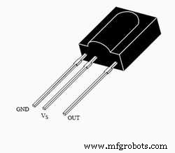
TV remote outputs high and low pulses at high frequency, thus, switching on and off the IR LED multiple times in a second corresponding to those pulses. Whenever the LED is ON , the TSOP goes low and when the LED is OFF, the TSOP is high (which means that it is also high when it is idle).
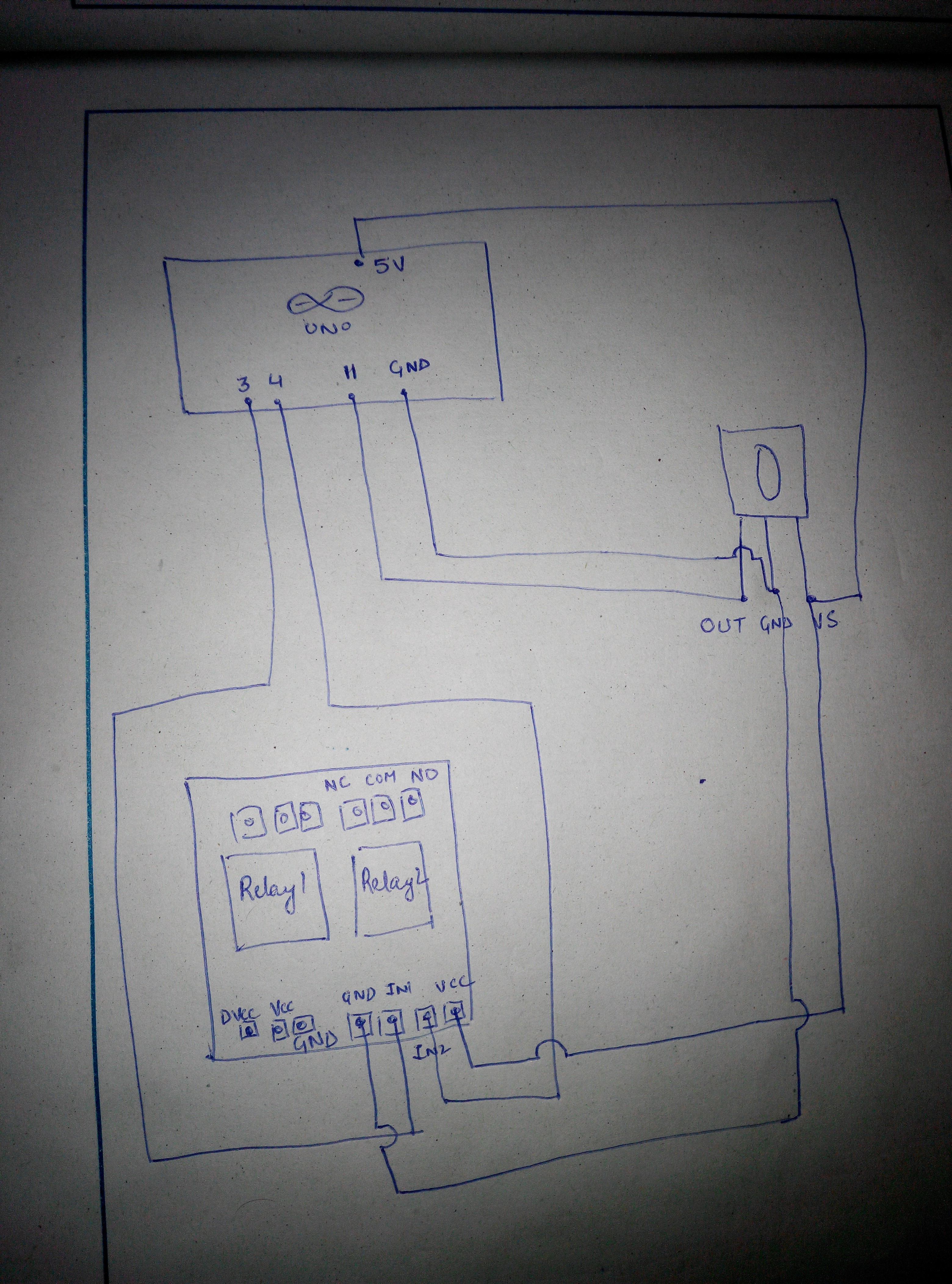
Here's the relay module :
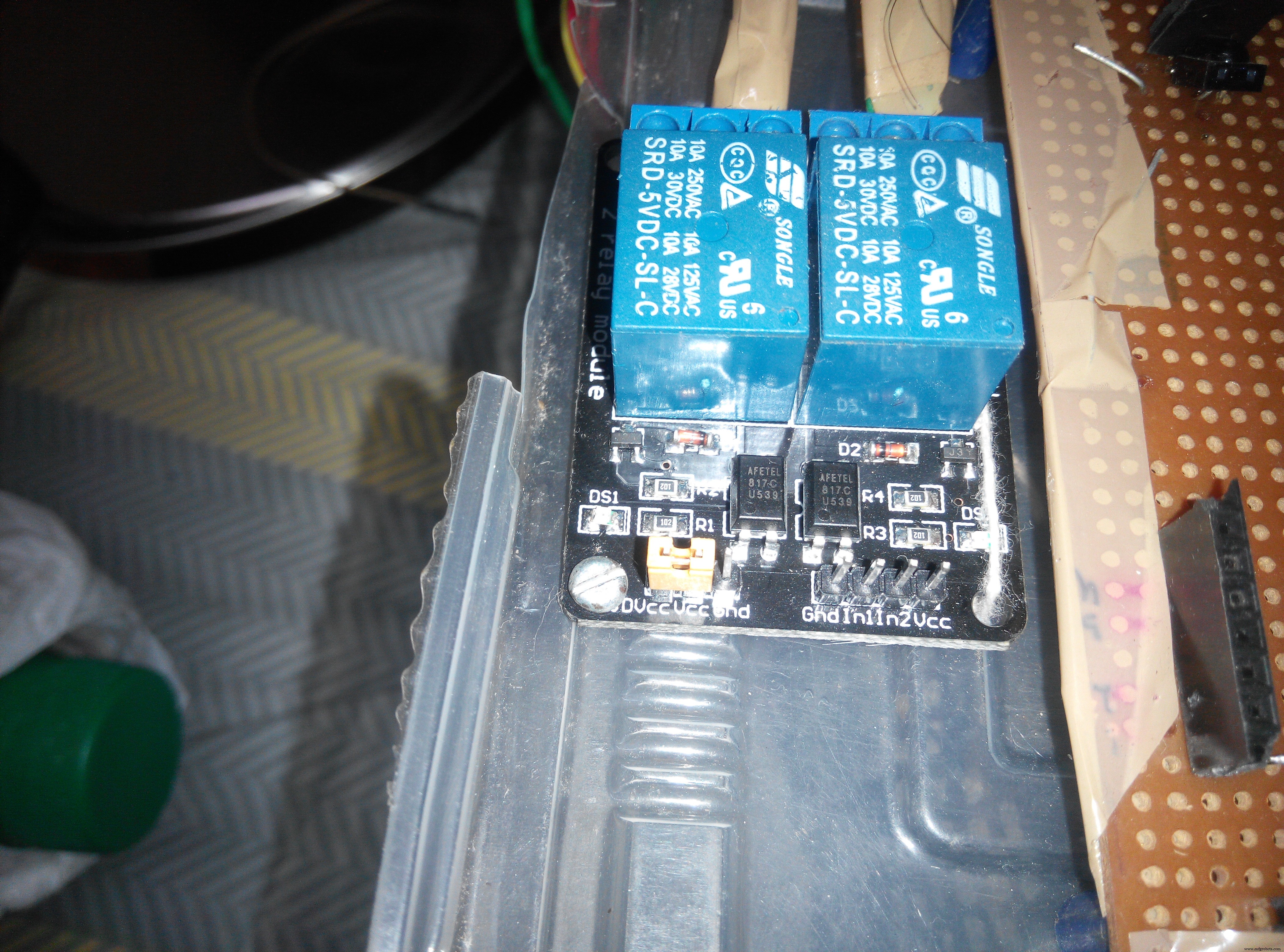
These inputs, when receive a LOW, switch the relay on i.e. the switch is 'closed'.
I have posted a video of TV remote switching the relay on/off. Due to absence of a working extension board with a bulb holder, unfortunately, I can't post a video of the lamp turning on/off. But I will post it soon. Here's the connection for connecting the lamp to the relay :
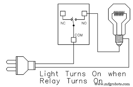
In my module too, from left to right- the 3 pins are: NC (normally connected), COM (common), NO (normally open). Connect the live wire to the bulb as shown. You can solder the entire project and install it inside your switch board to control your tubelight, fan, lamp etc.
NOTE: On the left side of relay module, there are 3 pins: DVcc Vcc and GND. I strongly suggest you to remove the jumper and give the DVcc pin a separate 5V supply because it is connected to an optocoupler (which prevents physical connection between high ac voltage and the microcontroller) so that in case of spikes, your microcontroller is not damaged.
Code
- Arduino code
Arduino codeArduino
KEEP IN MIND THAT YOUR REMOTE KEYS WILL SIGNAL DIFFERENT HEX CODES. THE HEX CODE IN THIS EXAMPLE ARE JUST FOR EXPLAINING.This code makes use of the "IRremote" library. You'll have to install it from 'library manager'.
The relays are switched on when LOW. So, when a certain HEX code is received the pin connected to the 1st relay is given LOW and for some other HEX code, it is given a HIGH so that the relay is switched off
#include <IRremote.h>
#include <IRremoteInt.h>


int RECV_PIN=11;

IRrecv irrecv(RECV_PIN);
decode_results results ;

void setup() {
  // put your setup code here, to run once:
  pinMode(3,OUTPUT);
pinMode(4,OUTPUT);
Serial.begin(9600);
irrecv.enableIRIn();
}

void loop() {
  // put your main code here, to run repeatedly:
if(irrecv.decode(&results))
{
  Serial.println(results.value, HEX);
 translateIR();
  irrecv.resume();
}
}
void translateIR()
{
  switch(results.value)
  {
    case 0x80BFC13E:
    digitalWrite(3,LOW);
    break;
     case 0x80BF4BB4:
     digitalWrite(3,HIGH);

     break;
    case 0x80BF837C:
    digitalWrite(4,LOW);
     break;
    case 0x80BF9966:
    digitalWrite(4,HIGH);
     break;
  }
}
Schematics
From left to right- OUT , GND , VS.OUT is connected to pin 11. VS connected to 5V pin of arduino and GND connected to gnd pin of arduino. LED's cathode is connected to pin 3, which when LOW , will switch on the ledir.fzzU can ignore the LED. and connect the relay pin insead.
(as shown in the next image)
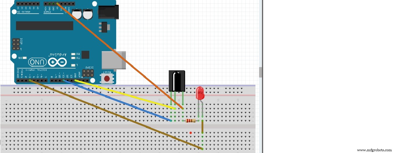 image looks dull, but shows good quality on zooming.
 Give the 'DVcc' a separate 5V
 A hex code will be displayed on monitor , everytime you press a button on the remote
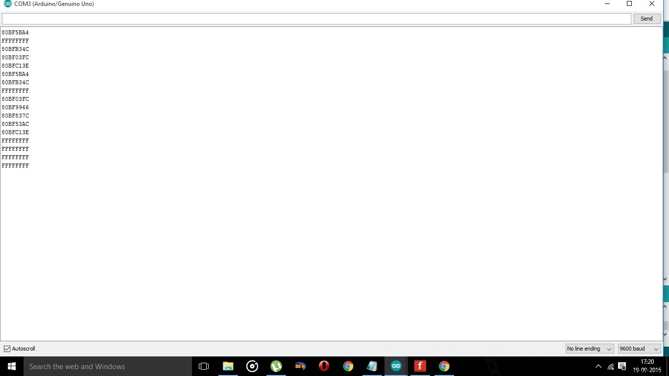 VID_20160919_161629.mp4VID_20160919_174751.mp4
Manufacturing process
- Temperature‑Controlled Fan: DIY Relay System for Media Furniture Cooling
- Build a Multi‑Sensor Temperature & Light Monitoring System with Raspberry Pi & DS18B20
- SMS‑Controlled Smart AC Power Switch with Raspberry Pi & Hologram
- ROObockey: Precision‑Assisted Remote‑Controlled Street Hockey Robot
- Gesture‑Controlled RGB Table Lamp – Interactive, Hands‑Free Lighting
- Arduino‑Based Remote‑Controlled Pet Feeder: DIY Kit & Build Guide
- Capacitive Touch LED Switch with Arduino UNO – Easy DIY Project
- IoT Integration: Remote Arduino Control via Windows 10 UWP Apps
- Bluetooth‑Controlled Pick‑and‑Place Robot Kit: Arduino UNO + 2‑DOF Arm & Smart Car Chassis
- Intelligent Disinfection Tunnel: Automated Sanitization for High‑Traffic Areas